First of all, let me say that I am in no way an expert with regard to satellites, microwave operations, or anything else. This is meant to be more of a crude beginners guide. Experts will probably cringe – that’s fine!
A little bit about Es’Hail-2
Es’Hail-2 (QO-100) is a geostationary satellite at 25.5° East which carries transponders (devices for receiving and re-transmitting signals) usable by radio amateurs. These two transponders are the first amateur radio transponders to be put into geostationary orbit and are expected to link radio amateurs from Brazil to Thailand.
Es’hail-2 will carry two such transponders, operating from the 2400 MHz band into the 10450 MHz band. A 250 kHz bandwidth linear transponder intended for conventional analogue operations (SSB, CW, etc.) and an 8 MHz bandwidth transponder for experimental digital modulation schemes and DVB amateur television. The operating guide provided by AMSAT-DL asks that users refrain from using FM on the narrowband transponder.
Narrowband Linear transponder
2400.050 - 2400.300 MHz Uplink
10489.550 - 10489.800 MHz Downlink (Vertical Polarisation)
Wideband digital transponder
2401.500 - 2409.500 MHz Uplink
10491.000 - 10499.000 MHz Downlink (Horizontal Polarisation)
With these linear transponders, any signal that the satellite receives in the input frequency range will be linearly translated to the output frequency range. As a signal power increases, so will the signal at the output; as the signal frequency increases, so will the output signal. And so it goes.
You can find out lots more information about the Es’Hail-2 satellite (and others) from the AMSAT-UK Es’Hail-2 website.
Why this page?
Following Noel G8GTZ‘s talk on Es’Hail-2 at the RSGB Convention 2018, I started collecting the parts required to put together a receive system. At the time of Noel’s talk, I remember thinking how he’d made the process sound simple. It wasn’t until I started playing with the setup that I actually found how simple the process was. More on this later…
Yesterday, I stumbled across a link to the BATC’s Es’hail-2 Ground Station website which has links to their wideband (think HD TV) and their narrowband (think SSB, CW) web receivers. The hardware is located at the Goonhilly Earth Station in Cornwall (IO70JB). More details can be found on the Es’Hail-2 BATC website.
If you have used a WebSDR online before, then the narrowband SDR will be familiar to you. The wideband monitor will probably not be familiar, but it is very useful if you are looking to experiment with digital amateur television (DATV) transmissions – more on this later. Since we’re interested in doing the receiving ourselves, we just note is that such web SDRs and monitors are a fantastically useful resource. There are of course many other similar resources.
Ultimately, this is the page that I wish I had found when I started out on this path a couple of days ago… You are welcome to contact me if you spot errors, etc.
Antenna talk: Dishes, LNBs & Feeder
A satellite dish is a type of parabolic antenna that is highly directive and therefore has a high gain. In simple terms, the dish collects incoming radio-waves over a large area and focuses them towards a central point.
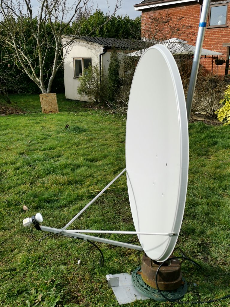
This point is usually the front of an low-noise block (LNB). The larger the dish diameter the more gain the dish will have – but – the sharper the beam, and so the more critical the alignment. Common dish sizes for receiving Es’Hail-2 are in the range 80 centimetres to 1.2 metres diameter. My dish, pictured below, is 1.2 metres diameter. Because the dish is highly directive (i.e., it’s beam is very sharp, like a laser pointer is with light), it requires careful adjustment.
Where do I aim the dish?
The AMSAT-UK Es’Hail-2 website tells us that the satellite is at 25.5° East. This means that the satellite is at 25.5° East of the meridian line. You will need to find the azimuth and elevation, i.e., the direction and tilt of the dish, yourself, since this depends on your longitude (distance from the meridian line) and latitude (distance from the equator). I have used the SatLex tool (below image), but many other online tools exist (DishPointer, SatSig) to help you. When using such tools, if they don’t have Es’Hail-2 in their index, BADR4/5/6 or EutelSat25B are close enough for now.
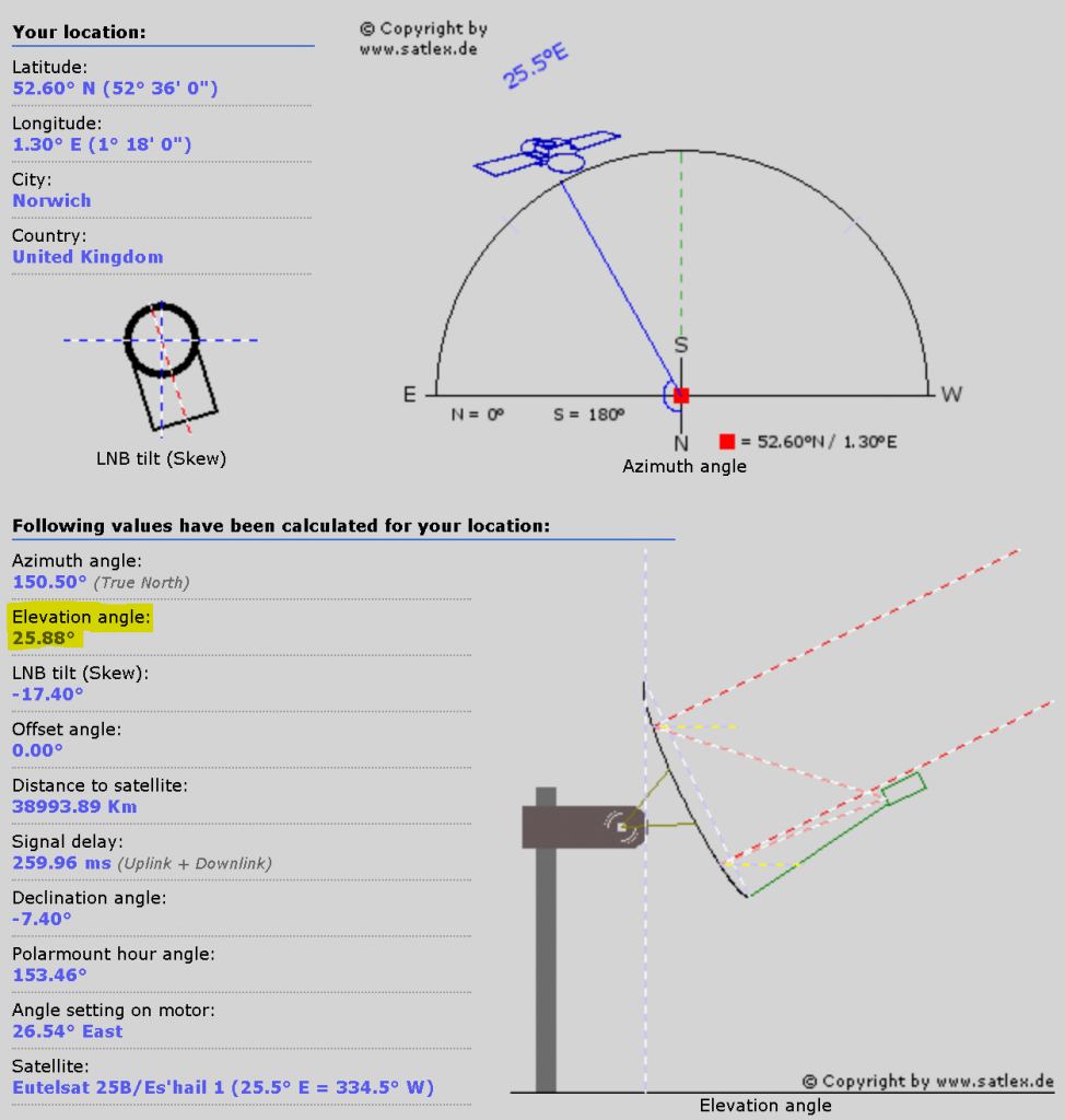
As you can see, the top half of the above image shows you a view due south, and the satellite location in your field of view. You’ll see the elevation angle of 25.88°, which I’ve rounded to 25.9°. You’ll have to tweak a little for maximum signal, regardless of how well you do this step, but it really helps to get the alignment as good as you can before you start. You will also see the ‘true’ azimuth angle, here 150.50°, which is the angle your dish should point to, and corresponds to a simple calculation between your longitude, the satellite’s position in space, and the meridian line.
The only other point to note in the above figure is the “LNB Tilt” of −17.4° (note, minus). Without proper knowledge, it is tricky to set the LNB skew without the LNB receiving a signal, so for now, lets press on with getting the dish mounted. We’ll come back to LNBs later.
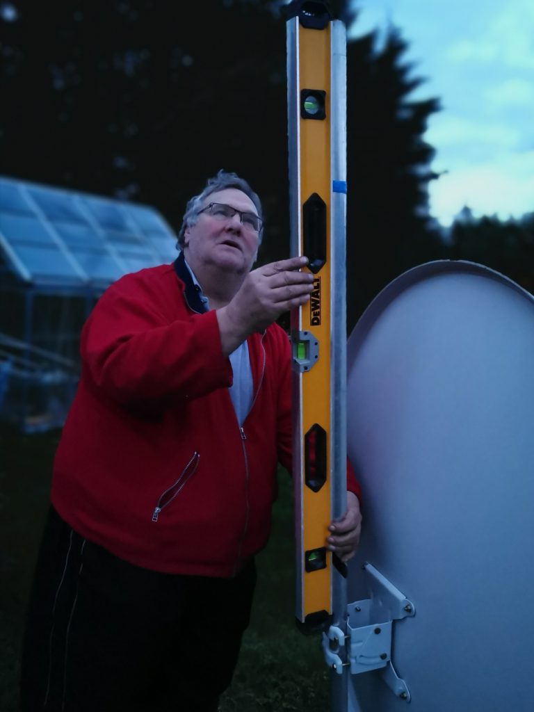
Getting the dish pointed at the satellite is, without doubt, the hardest part of the entire undertaking. On the right, you see Chris G8OCV helping to align the dish holding a spirit level. Since it is my policy to only ever do antenna work in the dark, on a cold evening, preferably in rain, he’s very enthusiastic! But he always helps!
For my QTH in Norfolk UK, the elevation worked out to be 25.9°. This is the elevation, i.e., the angle of the dish’s beam to the horizon. The dish’s beam points upwards 25.9°. We also know the azimuth of the satellite is 25.5° East, which corresponds to a true heading of 150.5°. These are the two coordinates we need to know to aim the dish.
Once the dish support pole was absolutely vertical, the elevation adjustment on the satellite dish can be done using the angle markers on the dish bracket. The azimuth 25.5° East is translated to 150.5° as taken from the satellite pointer website. I used a compass to initially align the dish. Some warning/disclaimer about the difference between ‘true’ North and ‘magnetic’ North belongs here. It didn’t cause me any trouble, but your experiences may be different. If you’re using a temporary post in the ground/umbrella stand, make sure it is heavy enough not to blow around in the wind. Mine wasn’t until we added some concrete weights.
Some words on LNBs
This section may sound a little scary, but I have tried to explain some of what is going on inside the LNB – don’t be put off! The low-noise block (LNB) is something that sits at the focus point of many commercial satellite dishes. The dish focuses the radio signals to a point – usually into the LNB. The LNB has a low noise amplifier to increase the level of the weak signals received by the dish. Since satellite downlink frequencies are well over 10 GHz, that would require some very fancy coax to get the signal into your house. So the LNB also mixes the received signal with a local oscillator (LO) frequency that it generates itself, in order to reduce the frequency of the received signal – this LO frequency is switchable to allow different frequency ranges to be received. Finally, the LNB has a polarisation switch, changing between horizontal and vertical polarisation. This is, of course, a gross simplification of what is going on, but is enough for now.
Without going into too much detail beyond what feels strictly necessary, the switching of LO frequency and polarisation are controlled by signals fed to the LNB from the shack-end of the coax. The LO frequency defaults to 9.75 GHz, but is switched to 10.6 GHz when the LNB receives a 22 kHz tone on the feeder. Since the LO is outside in the cold, the frequency reference is prone to thermal drift. You are strongly recommended to find an LNB that has it’s LO frequencies derived from a phase locked loop (PLL) as opposed to an dielectric resonator oscillator (DRO). A more advanced configuration is to purchase a dual-port LNB, and use one port for the feeder return to the shack, and ‘hack’ the LNB such that the second port serves to accept a frequency reference that can be provided. You do not need to do this, an off the shelf LNB will work, but a PLL variant is strongly recommended. If you hear very garbled or warbling sounding sideband or it is unresolvable altogether, it may be that your LNB is using a DRO as the frequency reference.
The polarisation is either vertical when the LNB is powered at 12V DC, or horizontal when powered at 18V DC. Often hams will only use the 9.75 GHz LO frequency, since then no 22 kHz tone is required. Some ham’s rotate the LNB physically to change polarisation, while others set the LNB between vertical and horizontal, thus receiving both simultaneously but with losses. I opted for supplying either 12V or 18V to the LNB and switching polarisation electronically from inside the shack. I have not, as yet, needed to change the LO frequency.
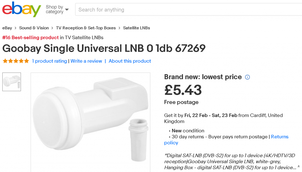
Everything on this page was done with a Goobay 67269 Single Universal LNB. There is lots and lots of information on LNBs if you search around online. The BATC has some information on LNBs, as does UHF-SatCom Ku Band PLL LNB’s page. The key point is get a PLL based LNB, as recommended by others. Some of the recommended ones carry a heavy price tag as at the time of writing there is a huge demand, and relatively small supply. A few years ago I bought an Octagon PLL-based LNB for less than £10 delivered; now they cost over £130! I would have used that, but it was in boxes packed for moving! Unfortunately for radio hams, sellers have realised that PLL based LNBs are more valuable to us, and so their price is gradually increasing.
Feeder
I had a bit of discussion with friends online about what feeders were being used. Most people have, I guess obviously, opted for satellite coax. This is RG6 coax, and has a solid centre pin suitable for use in F-connectors. This is also available cheaply on eBay, often kitted with ten F-connectors. I paid around £9 for 50 metres. In an early instance, I got away with using RG213 (which is 50 Ohm, not 75 Ohm) and some F-connector adaptors, but the LNB gain makes up for a lot of small misdemeanours. RG6 satellite coax is the way to go! The image below shows my mash of connectors and adapters to overcome my lack of a solid centred feeder such as required by F-connectors.
Connecting it all up
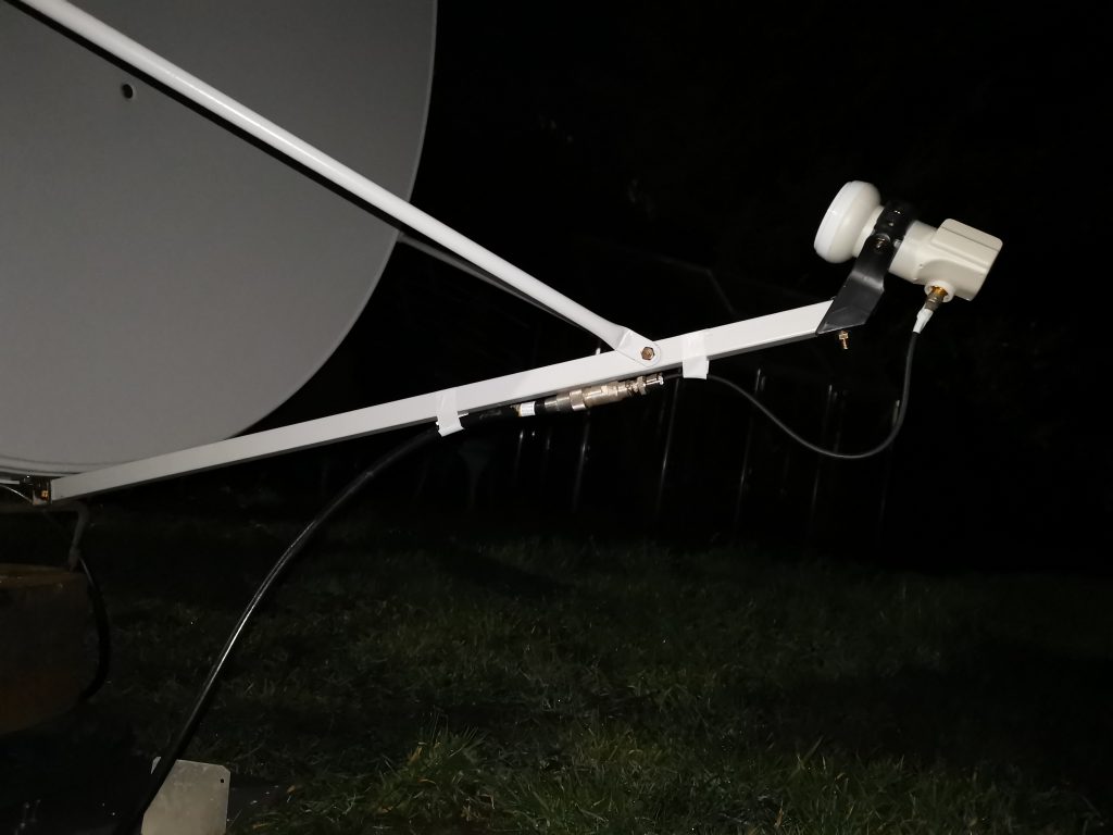
Terminate the LNB end of the feeder with an F-connector, and seal it up to keep the rain out. Mount the LNB in the dish’s LNB mount. You need to be able to twist the LNB to adjust the LNB tilt, but don’t want anything to move of it’s own accord.
The next obstacle is to power the LNB. I did this by hacking about with an RTL-SDR dongle and building in a bias tee inside – details in the “LNB Bias inside an RTL-SDR Dongle” section, below. If you have a bias tee already, you may be able to use that provided it is suitable for use at around 740 MHz. Power the LNB with 12V to select vertical polarisation with 9.75 GHz LO, ideal for the narrowband transponder of Es’Hail-2.
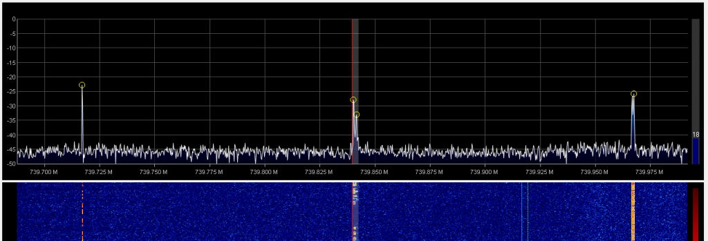
The centre of the Es’Hail-2 narrowband transverter downlink is 10.489675 GHz. If we use the 9.75 GHz LO, we expect to see an intermediate frequency (IF) of 10.489675 − 9.75 = 0.739675 GHz = 739.675 MHz.
We are expecting to see signals in the 250 kHz bandwidth centred on 739.675 MHz. On an RTL-SDR dongle waterfall, you should see an increase in the noise floor between when the LNB is powered and when it is unpowered. If you do not, check your wiring. My LNB draws around 100 mA.
Tweaking the dish
As we alluded to earlier on in the dish section, we need to tweak the dish’s alignment. But to do this, we need to be receiving signals, and then take an opticians approach, of ‘better or worse’ with very tiny adjustments each time.
If you have followed these notes so far, you will have a receiver, or spectrum analyser or similar centred on 739.675 MHz, with your LNB in horizontal polarisation and a 9.75 GHz LO frequency.
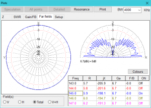
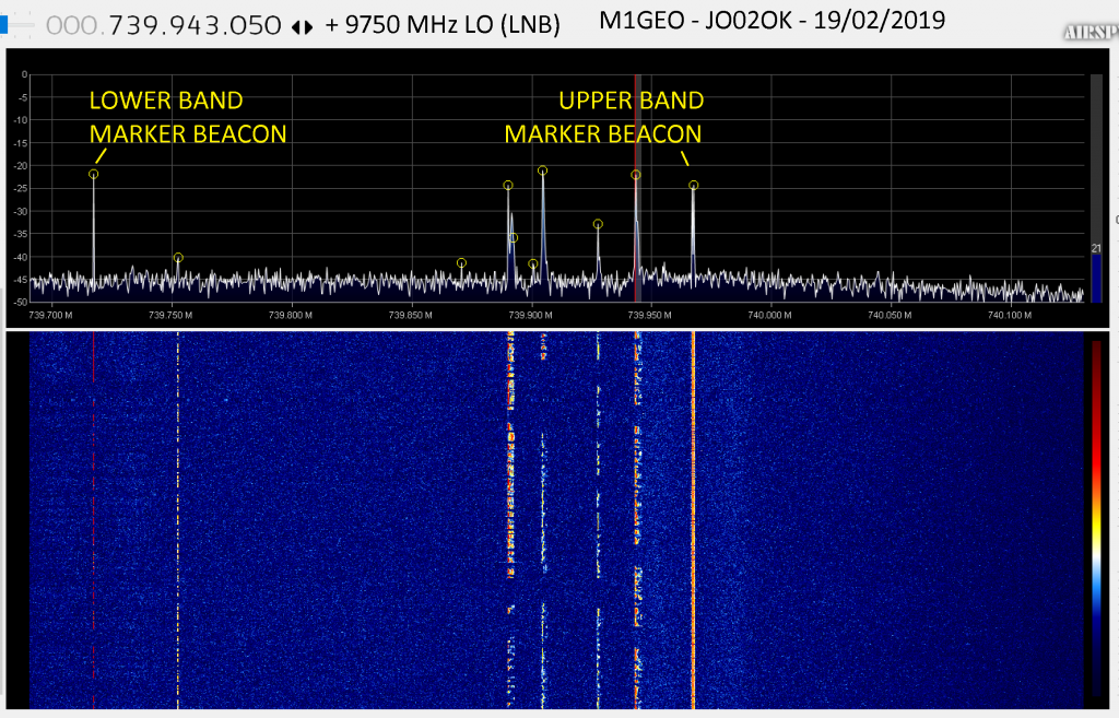
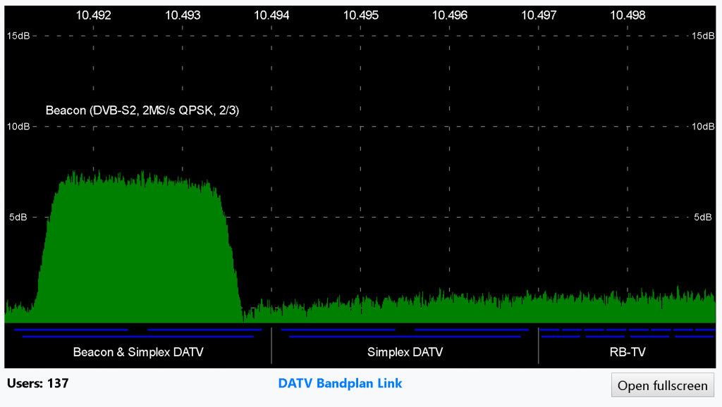
The Es’Hail-2 narrowband transponder has will appear as a wide lump of raised noise floor, similar to what you see below. The raised bump is the transponder bandwidth, and the two signals present are the upper and lower band markers. They send CW and binary data, too. The transponder bandplan is outside the scope of these notes, but you can find it on the
AMSAT-UK Es’Hail-2 website. It roughly follows the usual bandplans for all-modes, with CW at the lower end, then digital modes, then SSB at the top.
When tweaking the satellite dish, adjust for the largest (highest) bump above the noise floor. You equally want the two beacons to be high above the transponder noise floor. Very slowly, in small steps, adjust the azimuth (rotation) of the dish stopping at the point that maximises the signal. Then adjust the elevation (tilt) of the dish to further maximise the signal. If you do not see anything on the waterfall, then you may need to make larger sweeps of the dish to find the satellite in the first place. This is where your care previously helps. As mentioned before, this is the trickiest step.
LNB Tilt/Skew
Once you have a good signal-to-noise (high bump above the noise with large beacon signals), you should adjust the LNB within the dish mount.
If you can electrically switch polarisation to horizontal (by feeding the LNB with 18V) then you should do this. With the antenna now ‘cross-polarised’ to the narrowband transverter, rotate the LNB to receive the minimum signal you can. What you are doing is looking for the maximum amount of cross-polarisation. It is easier to adjust for the null than for the signal itself, and you will achieve a better adjustment this way. If you cannot switch the LNB polarisation electronically, then you should adjust for the maximum signal with rotating. Rotate the LNB towards the LNB tilt angle (for me this was −17.4°), going past that angle to ensure you find the minimum or maximum as appropriate.
You may also like to adjust your LNB backward and forward in the mount to try and find the optimum focal point, although this point is usually specified pretty clearly on the dish’s paperwork. Either way, with the LNB now in the correct polarisation (12V feed, vertical for the NB transponder), move the LNB backd and forth looking for the largest signal.
These steps may be difficult to do, as your body will cast an ‘shadow’ on the dish – either hide out of the way as you adjust, or, tweak and step back. You get the idea.
Once you’ve done that, bolt everything up tight and you’re good to go!
Receiving Narrrowband Modes
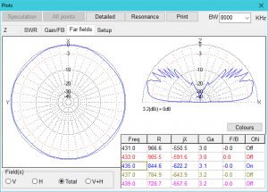
If we zoom in a little from the spectrum display we saw when aligning the dish; such that the markers are now on the outsides of the waterfall, we see more of a ‘band view’, and the transponder frequency response looks relatively flat. This screen-grab was also taken with several signals visible.
As with any other SDR you may have used, clicking on the signals will allow you to demodulate them.
Below, OH1ZAA calling CQ:
OH1ZAA calling CQ and UN6PD returning
Receiving Digital Video Amateur TV
The Es’Hail-2’s wideband DVB-S2 beacon on 10.492,500 GHz is always transmitting video. This beacon was my very first reception of DATV. I am still finding out about this, so my experience here is minimal, but perhaps it is of some use. You should defer to the BATC’s Receiving DATV guide for detailed information.
Digital television has many different standards, as you might expect. The key factors are the modulation type (how data is encoded onto the RF carrier), sample rate (in samples per second), picture mode (DVB-S, DVB-S2, etc) and FEC (or forward error-correction). As well as this, streams have a PID (packet identifier) which identifies the program – all we need to do is set this correctly. The standard is set out in the ETSI EN300-468 specification if you want to learn more. You don’t need to.
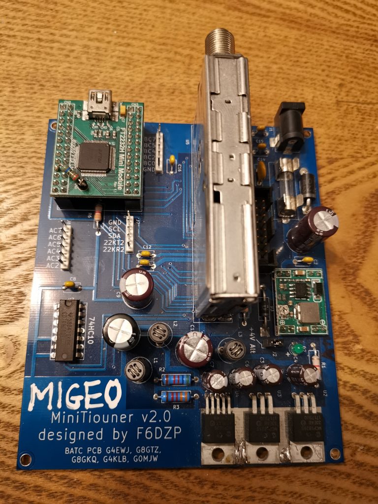
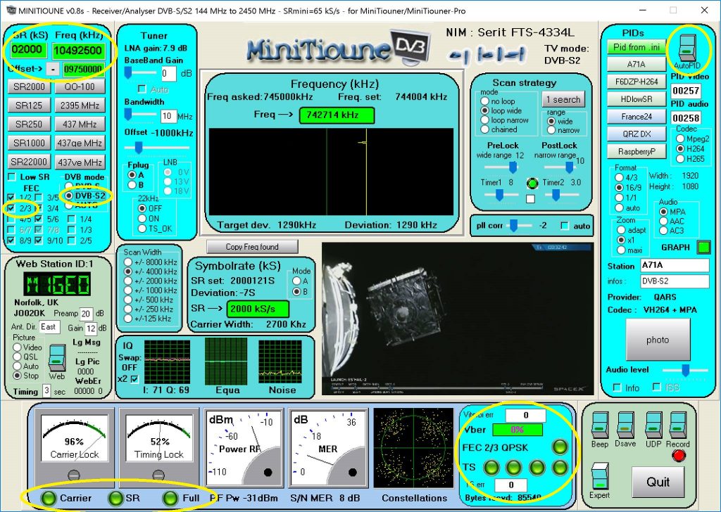
Most amateur signals vary in the above listed parameters to what is used commercially. While a standard digital TV multiplex may be 8 MHz wide, radio amateurs typically use much smaller bandwidths, and what is called Reduced Bandwidth TV (RB-TV). Commercial receivers usually do not support these configurations, so a special receiver (the MiniTiouner by F6DZP and others) was developed from modules and allows fine control over all of the parameters associated with digital video transmission.
This remainder of this section concentrates on the MiniTiouner. However, there are two SDR based options available. I cannot offer any words on these, except to highlight their existence:
- Lean SDR: A lightweight, portable software-defined radio (C++)
- SDRAngel: SDR Rx/Tx software for Airspy, Airspy HF+, BladeRF, HackRF, LimeSDR, PlutoSDR, RTL-SDR, SDRplay RSP1 and FunCube (C/C++)
- DATV Express: Software and (discontinued?) hardware
The ‘MiniTiouner’ Receiver
The MiniTiouner by F6DZP and others is a USB tuner designed specifically for Amateur TV use which natively covers 143 MHz to 2450 MHz and is suitable to receive Es’Hail-2 and a number of other amateur bands with no modifications or additional up-converter. It is available from the BATC and other sources. See the BATC MiniTioune page for more details.
As a short note, the term ‘MiniTiouner’ with an ‘R’ at the end refers to the hardware PCB; the term ‘MiniTioune’ (no ‘R’) refers to the software.
Most amateur TV transmissions are made using Reduced Bandwidth DATV (RB-TV) with a bandwidth below 1 MHz. To date, 90% of the DATV transmissions on Es’Hail-2 (QO-100) have used RB-TV.
The MiniTiouner comes as a kit from BATC, and took me roughly an hour to build. Follow the build notes on the BATC website.
I then had to register on the VivaDATV forum to obtain F6DZP’s MiniTioune software (post link here) – I’m not sure why I had to register, but, I did. At the time of writing, this is software version 0.8s. For instructions on how to install this, visit the BATC’s MiniTiouner Software page. Don’t forget to install the accompanying USRC and LAVFilters packages, too. I did; you get no video! 🙁
An issue that I faced is that the USB connection between my computer would drop randomly causing the MiniTioune software to crash. This is supposedly solved by using a Lindy Cromo Lindy cable USB 2.0 type A/mini-B 1m long, but after spending £10, the issue still persists.
Before you fire up the software, open the minitioune.ini file and edit the following fields: OM_ID (callsign), ForumPassword (forum password), Locator (QRA locator), Ville (location) and anything else you see fit. You’ll probably want to come back to this file from time-to-time.
The ‘MiniTioune’ Software
When the software first starts, you’ll see something like the image below – just wait a few seconds:
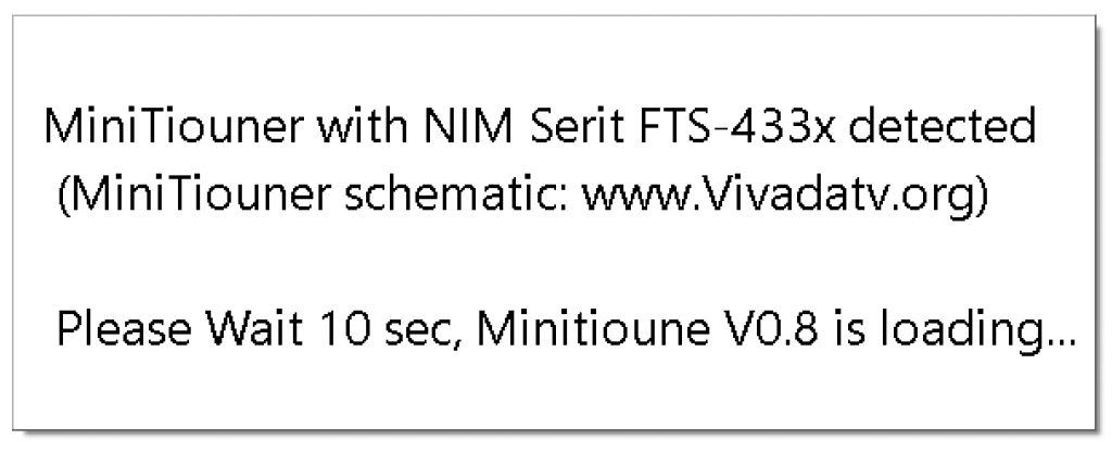
After a few seconds, you will see the main MiniTioune program window:
My advice would be to make sure you can receive the beacon before you move on to anything else, since the beacon has known parameters.
Receiving the Es’Hail-2 DVB Beacon
The first thing to note is that the wideband transponder is horizontally polarised, so you will need to supply 18V to your LNB to switch polarisation, or, rotate the LNB 90° in either direction. The MiniTiouner hardware has two jumpers which allow you to feed the input DC supply voltage into the LNB F-connectors via the Serit module. These are labelled LNB_A1 and LNB_A2 on the PCB, and can be found between by the DC input power jack. Then the whole MiniTiouner receiver is powered from either 12V or 18V as required.
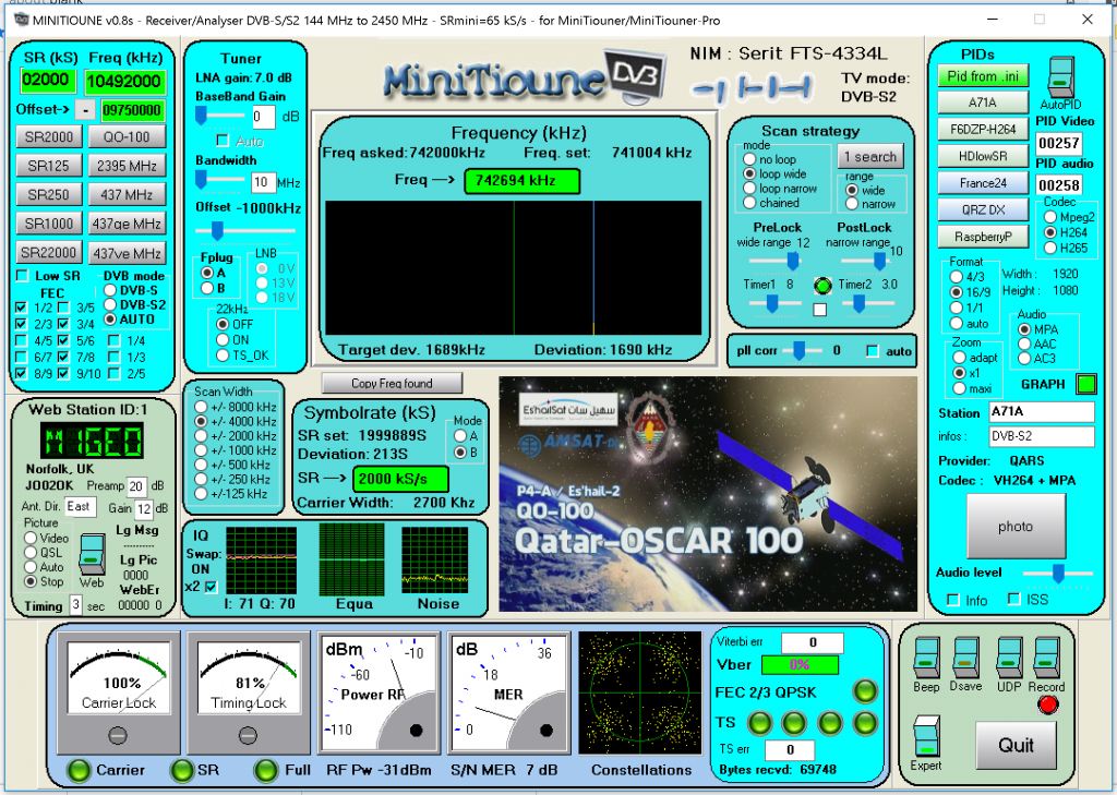
Next look to the top-left of the main MiniTioune window; you’ll see a place to enter the sample rate (SR) and a frequency (in kHz). The beacon frequency is centred on 10.492,500 GHz, and transmits DVB-S2 with 2 MS/s QPSK modulation using 2/3 FEC forward error correction.
If we enter 10492500 kHz into the frequency box, we also need to tell the MiniTioune software to accommodate for the frequency translation the LNB is performing. It is enough to say that the LNB provides a frequency offset of −9.75 GHz, so we indicate −9750000 kHz (note, minuses).
We’re told the sample rate is 2 MS/s, so we can enter this as 2000 KS/s in the SR box at the top left. Make sure you have selected either AUTO or DVB-S2 for the mode, and that you have the checkbox for 2/3 FEC enabled.
Looking at the BATC’s Wideband Transponder Monitor, it is possible to see the beacon transmission on the left at 10.492,500 GHz. You may also see other transmissions besides the beacons and we’ll look at that those in the next section.
As you enter the sample-rate and frequency, you should start to see some of the indicators at the bottom left of the MiniTioune window turn from red to green. Once the Viterbi decoder error goes to 0% (bottom centre-right), you should see video and hear sound! If you do not, then toggle the Auto PID button in the top right. This makes MiniTioune decode the incoming stream to find the video and audio transport streams and understand their codecs.
The clip below is a short section of the Es’Hail-2 DATV beacon:
Receiving the Es’Hail-2 DVB Beacon
The process of receiving an amateur transmission is very similar to receiving the beacon. The only difference is that you may not know the properties of the signal being transmitted. In this case, I have found that using the BATC’s Wideband Transponder Monitor to look at the signals can be very useful to help guess. You can see from the spectrum that the signal is much narrower than the beacon, so we can take a guess at the sample rate by knowing a few commonly used values. 125, 333, and 500 kS/s seem to be common, while some use 1000 kS/s in the simplex DATV window.
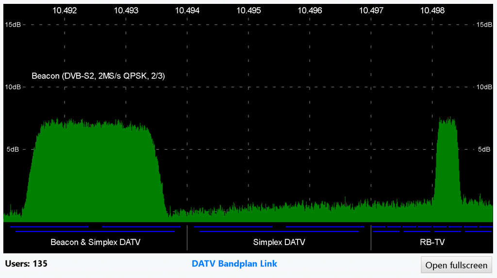
If you leave the common FEC options ticked and use AUTO mode selection, the MiniTioune software will magically recognise things after a few seconds, if you have chosen the right combination of options. There is, of course, another way:
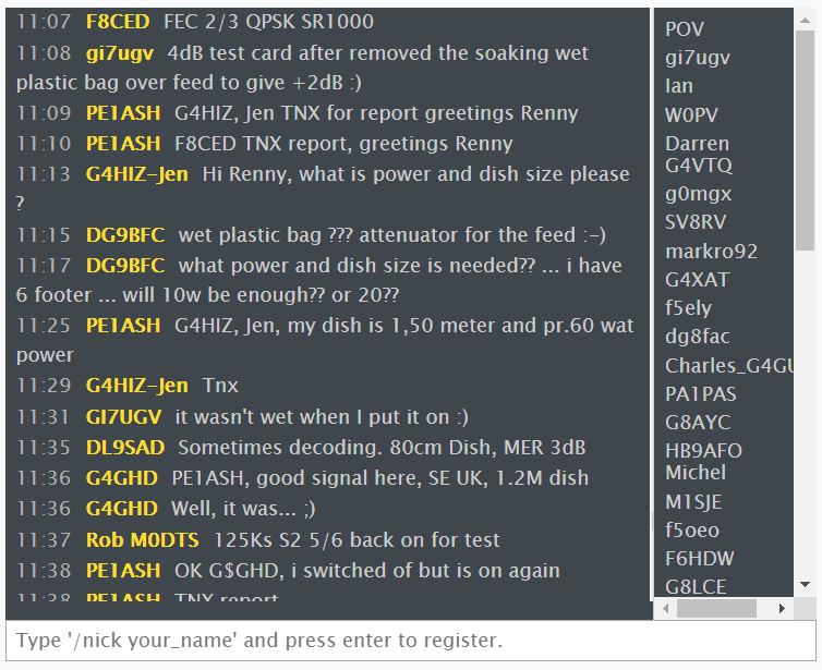
The BATC wideband transponder monitor page also includes a simple chat system, where users can advertise their settings. Above you can see F8CED and M0DTS advertising their settings.
Using a mixture of trial and error, as well as watching others talk in the chat, I have been able to observe a considerable amount of amateur test transmissions via Es’Hail-2.
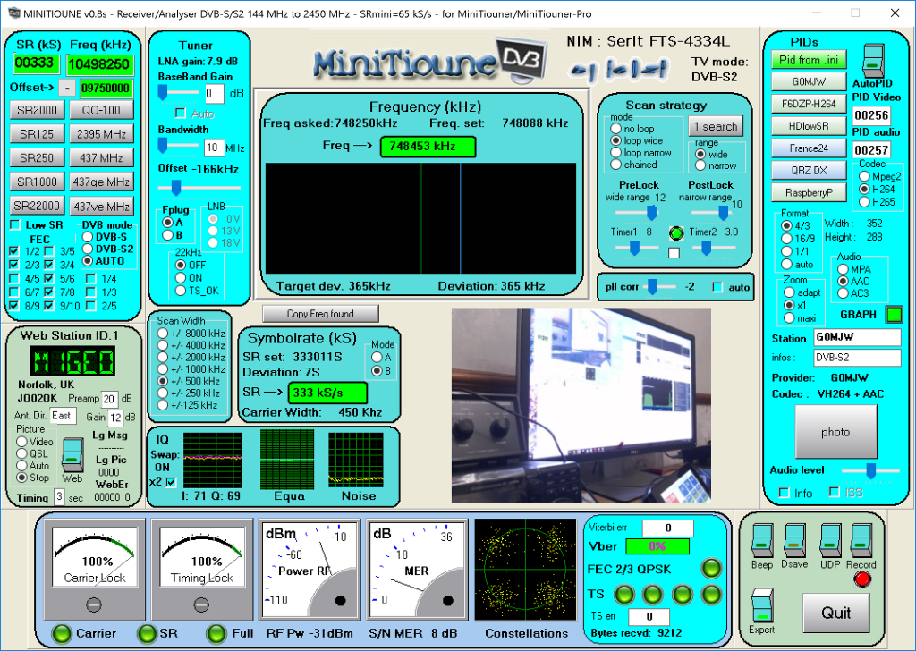
Mike G0MJW 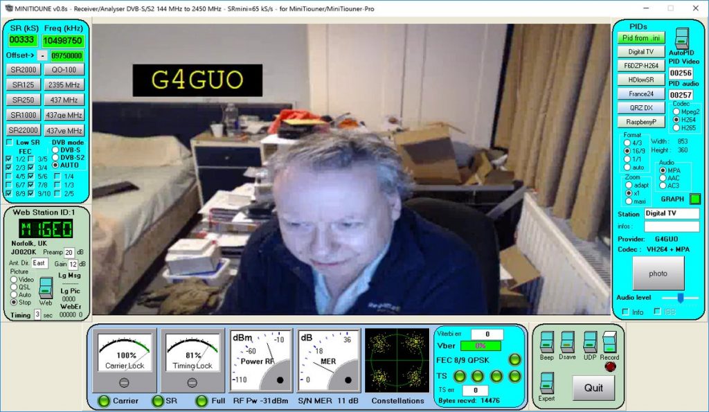
Charles G4GUO 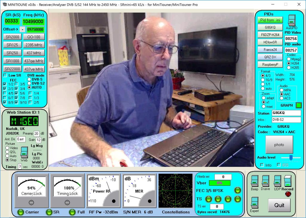
Dave G8GKQ
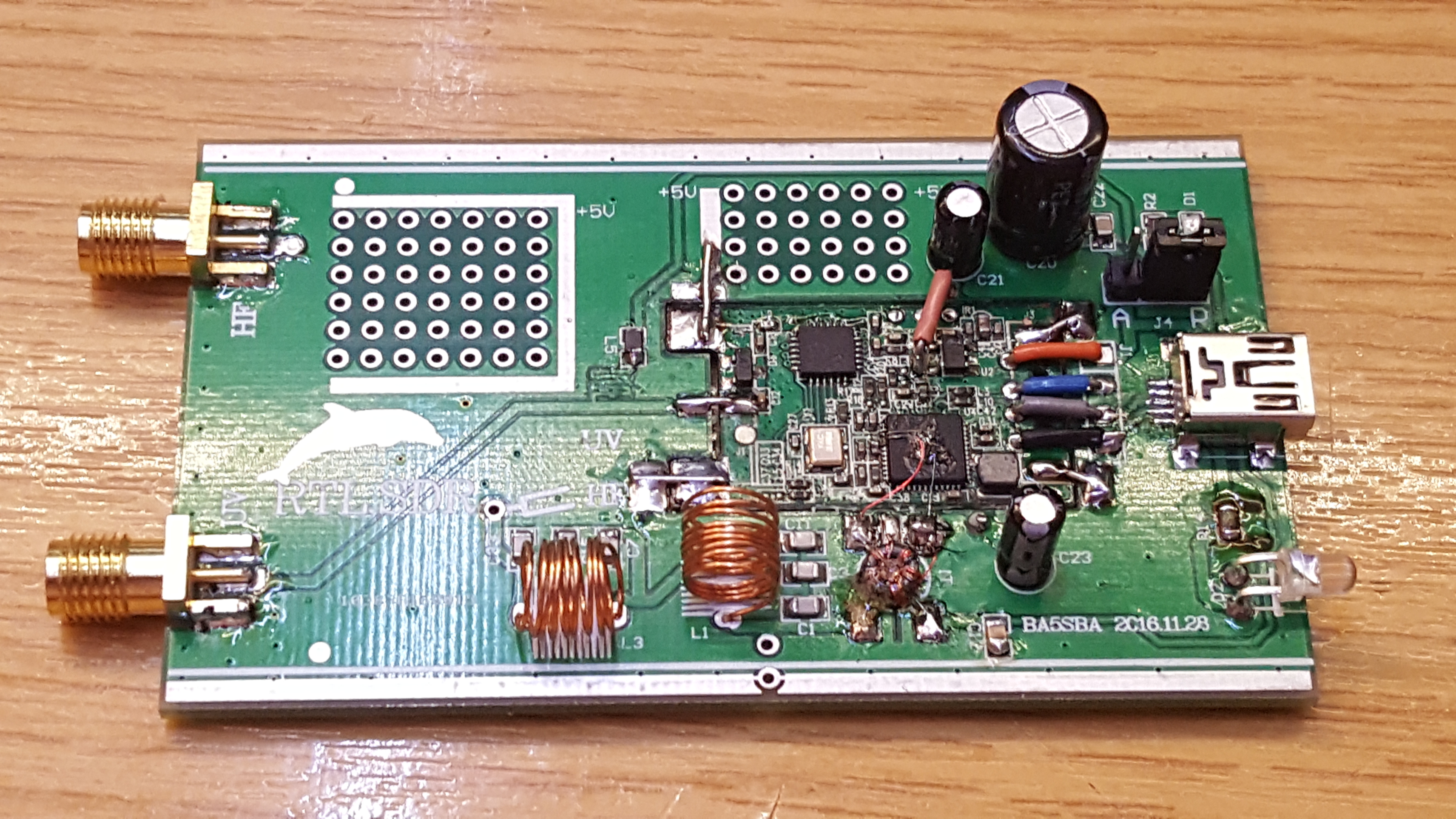
LNB Bias inside an RTL-SDR Dongle
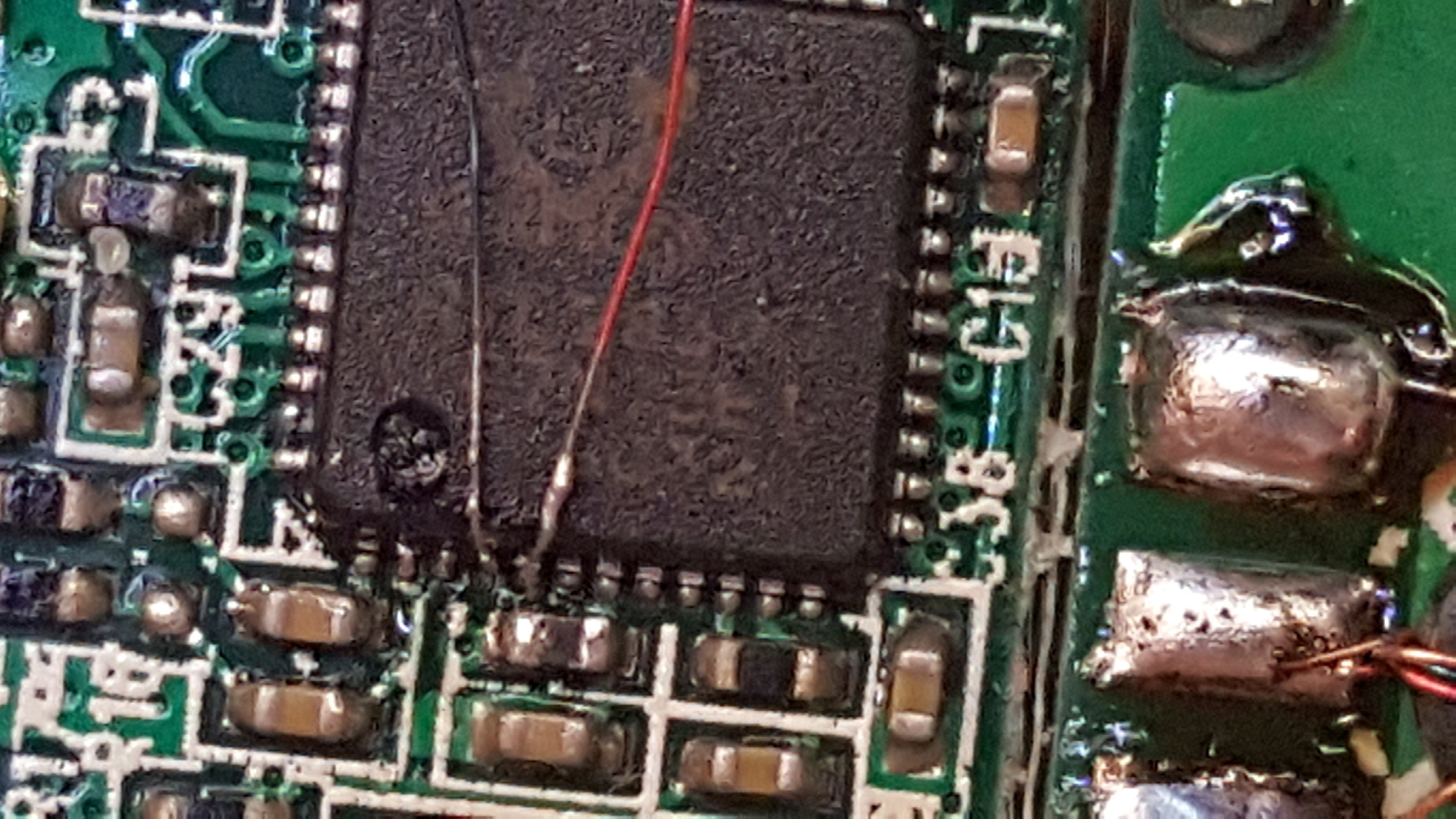
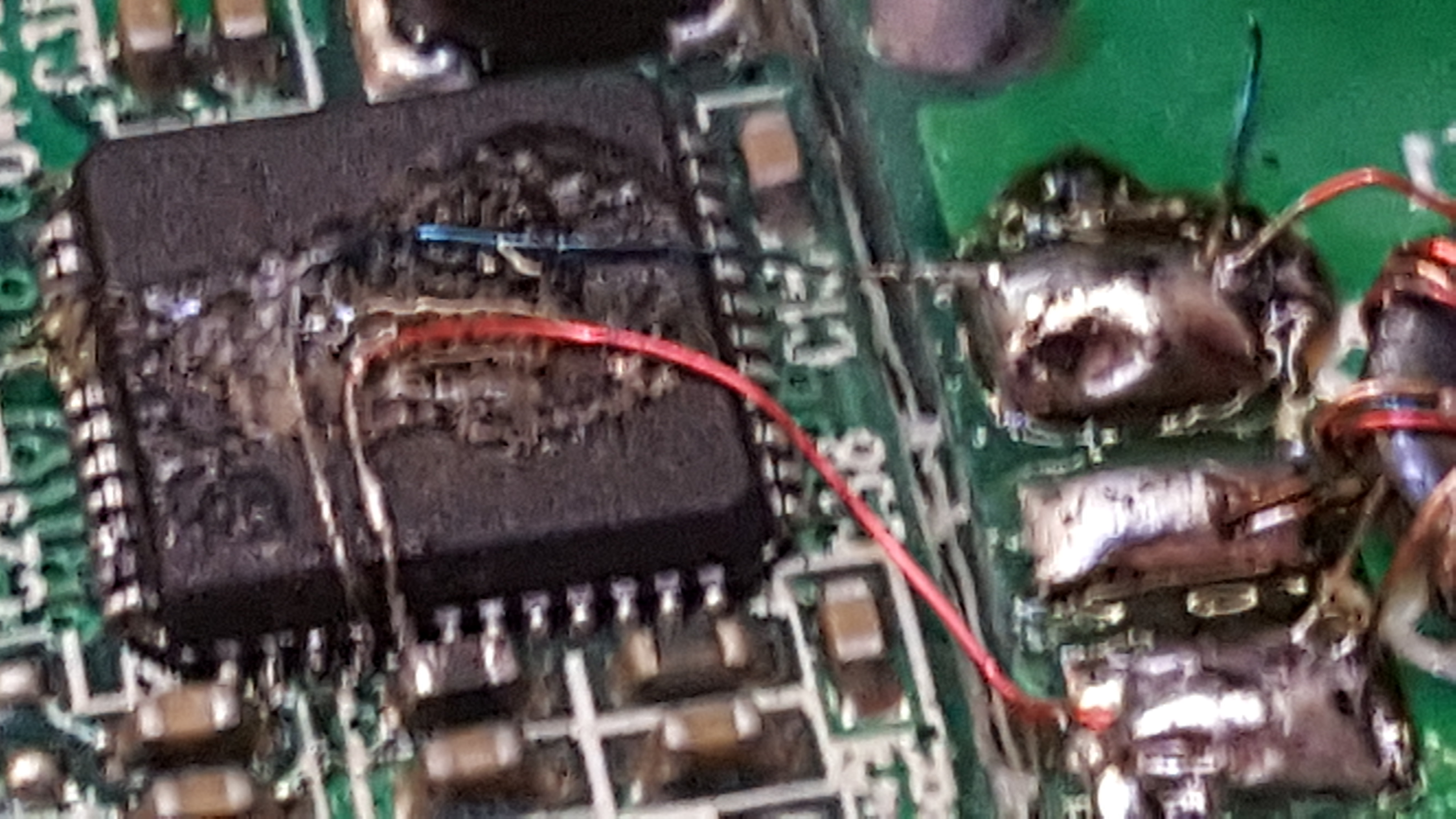
In order to tweak the dish alignment and also to receive narrowband transponder signals, I needed to power the LNB for use with an RTL-SDR Dongle. I had heard that some dongles have a bias tee included, and I was hoping to repurpose some of this since clearly it would only supply 5V.
I opened the New Gen RTL2832 SDR I had to look inside and noticed a DC bypass inductor to ground for static discharge, with capacitors leading to a DC blocking capacitor, limiting diodes and on into the receiver.
By standing the DC bypass inductor on end, and adding a decoupling capacitor on the now unused pad, I could create a very crude bias tee. I used a 1000pF and a 47nF capacitor to create some further blocking and add mechanical stability, and then I soldered on two power wires.
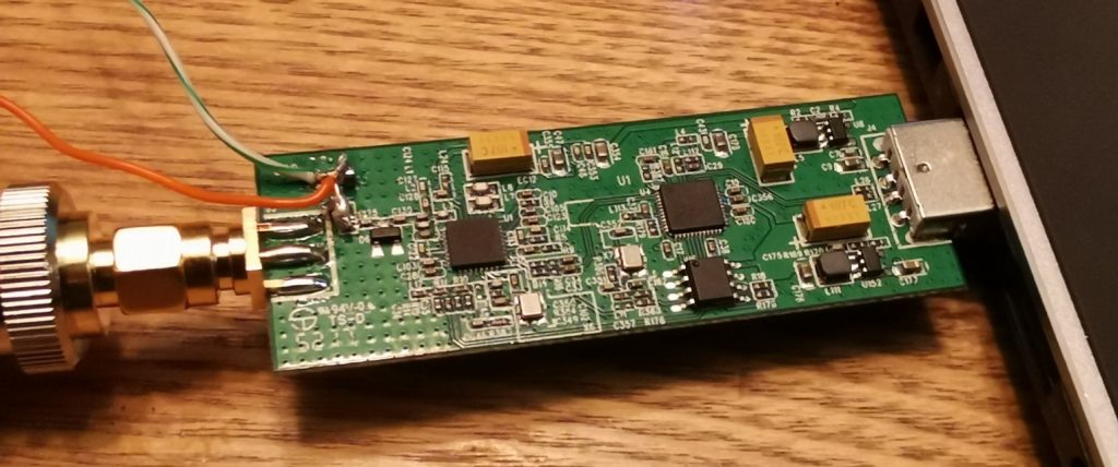
It doesn’t look pretty at all, but it does work, and is small!
Where next?
The next step is to get a transmitting station put together for 2.4 GHz. You may be interested in how I did this: 2.4 GHz TX with LimeSDR & EDUP WiFi PA.