
I was interested in the frequency stability and offset of the FunCube Dongle so I devised a simple method of testing it. Tuning the FCD to receive a frequency stable source (here, GB3VHF, which claims high long-term stability) will show up any drift in the FunCube Dongle. This is what I set out to do. If you use GB3VHF, please consider donating to GB3VHF which will help with the beacon’s upkeep.
Using a simple MATLAB Script (downloadable from here) the FCD is sampled at 96,000 Hz giving a nice and wide frequency range. Both I and Q channels are sampled and multiplied out to give a complex signal; this is then FFTed and filtered to give a window of 10KHz. The FCD PLL frequency is tuned such that the source signal is in the middle of the filter, here at 15KHz. A threshold is added to ensure that the data sampled is only for a good strong clear signal (we get a lot of noise here) and that the WSJT65 is rejected (this is FSK and would ruin our results).
When this original article was first written, it attracted quite a bit of interest. I had initially done it as an experimental idea – really just toying with the principles. However, I received a lot of feedback mostly pointing out flaws, errors and additions to my methods. I have therefore added a second attempt.
First Attempt
The device was left recording frequency drift over 24 hours and finally the graph plotted. Below, the graph shows two traces. The red trace shows the observed frequency of reception, the blue trace shows the average observed frequency over the time period. This average is 144,445,328 Hz. GB3VHF transmits on a frequency of 144,430,000 Hz, and so we calculate the average offset to be 15,328 Hz high over the time period examined. The first graph shows the smoothed data, whilst the second shows the raw data.
Second Attempt
The main criticism I received was that the FunCube Dongle was subject to fluctuations in frequency which caused the drifts observed in the first results – I believe this to be true. I initially decided that I could record the temperature throughout a 24-hour period and correlate this with the observed frequency. Then after thinking about it a little longer I decided that a better gauge of the frequency stability would be to place the FCD into an environment where the temperature was constant and then observe the frequencies drift. This was the basis for the Second Attempt.
I went about insulating a small cardboard box (which housed a replacement toner cartridge for my printer) using bubble-wrap, shredded newspaper, plenty of sticky-tape and some brown wrapping paper, I created my Thermally Controlled Box (patent pending, hehe):
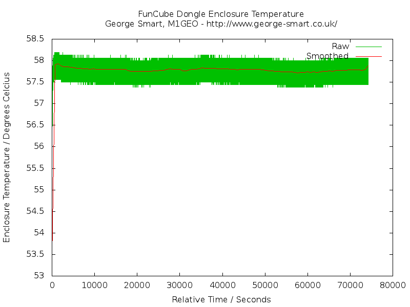
Inside the box is a small 80mm PC fan and a fibre-glass former with about 10 turns of resistance wire wrapped around. The fan blows over the resistance wire (which is hot) and warms the box up and distributes the warmed air around, ensuring an even temperature distribution. A Velleman MK138 Thermostat was modified slightly to provide a stable temperature inside the box and a Dallas Semiconductor DS18B20 one-wire thermometer was used to interface to the PC via arduino and USB to record the temperature into the computer. The configuration is a bit of a lash-up but it works and initial testing showed a reasonable temperature stability. The hysteresis on the Velleman MK138 provides a little bit of a ripple in the temperature, but I would suspect this to average out with the thermal resistance of the FCD case, and thermal mass of the FCD circuit board. The two images below show (left) the initial 10 minutes where the start up can been seen as well as the temperature ripple, and (right) the full temperature recording over the experiment shown below.
 |
 |
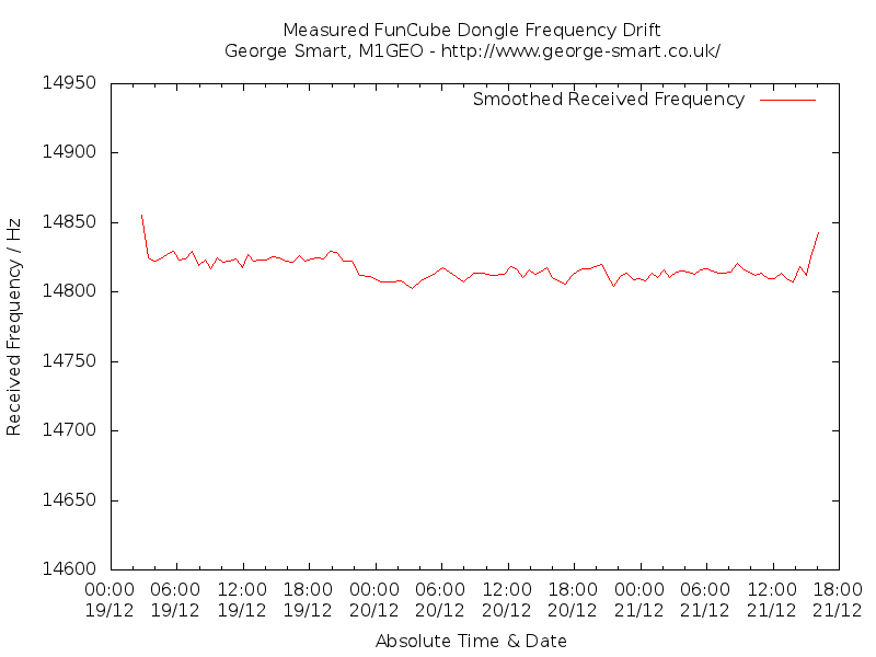
After convincing myself that this box really did hold up to the job of remaining constant temperature inside, I connected up the FCD as in attempt one and placed it inside the oven. I closely regarded the set up for some time to make sure that it was working as I expected and secondly, that it didn’t catch fire and burn my house down. Following some slight modifications to the MATLAB script the data for the stability at a given temperature (60 degrees Celsius). I should point out that these frequencies are an offset from 144.430000 MHz as defined in the FCD control software.
There is still some work to be done. I have a Rubidium frequency standard and a GPS frequency standard, and so I will endeavour to repeat these measurements again.
Frequency Drift vs Temperature
So from the second experiments, it is clear that the temperature plays are large role in the frequency offset. I have therefore decided to do one last experiment before I close this case forever. I want to look at how the temperature of the enclosure effects the frequency drift. By gradually increasing the enclosure temperature throughout a day, and plotting the results, with the offset frequency as a function of temperature, we finally we can see how things relate.
But you will have to come back for this, as I’ve not done it yet, and probably never will…