
Introduction
For the last 4 or 5 years I’ve been making printed circuit boards (PCBs) with the Toner Transfer method (sometimes called the Iron on method). This allows the use of non-photo-resistive PCB which is often much cheaper than that with the resistive layer. This is done by using a laser printer’s toner to protect the copper of the PCB from the acid (like the photo-resist traditionally would). I have had very good results from this method. I decided to share my method as a few people had asked. When making a PCB for programming my Tait T800 Series II Repeater for my EchoLink node, I decided to document the PCB creation process.
I don’t particularly design the board in any special way. I would suggest you use the biggest tracks you can for a variety of reasons; namely that it will transfer much easier and it will etch much quicker (less copper to dissolve) making the acid last longer. I have only used this method a couple of times to create double sided boards, but the same problems exist as with the resist method. I have made many many single sided boards using this method.
Printer and Paper
Printer
The printer you choose can effect the results of the toner transfer. Obviously it needs to be a laser printer (or an inkjet and then photocopy onto your paper of choice below). I have found Brother printers to work well – there was little research into this, simply that I’ve found them to be good printers and they’ve always worked well – I also own a Hewlett-Packard printer which also works well. I’m tempted to say that your printer doesn’t really matter. There is probably a slight difference between them, but not really enough to worry about. I’ve never used a printer that I couldn’t get results from. The printers I currently use are:
- Brother HL-2030
- Brother DCP-7030
- Hewlett-Packard Colour LaserJet CP1215 (in monochrome mode)
- OKI B4300
Paper
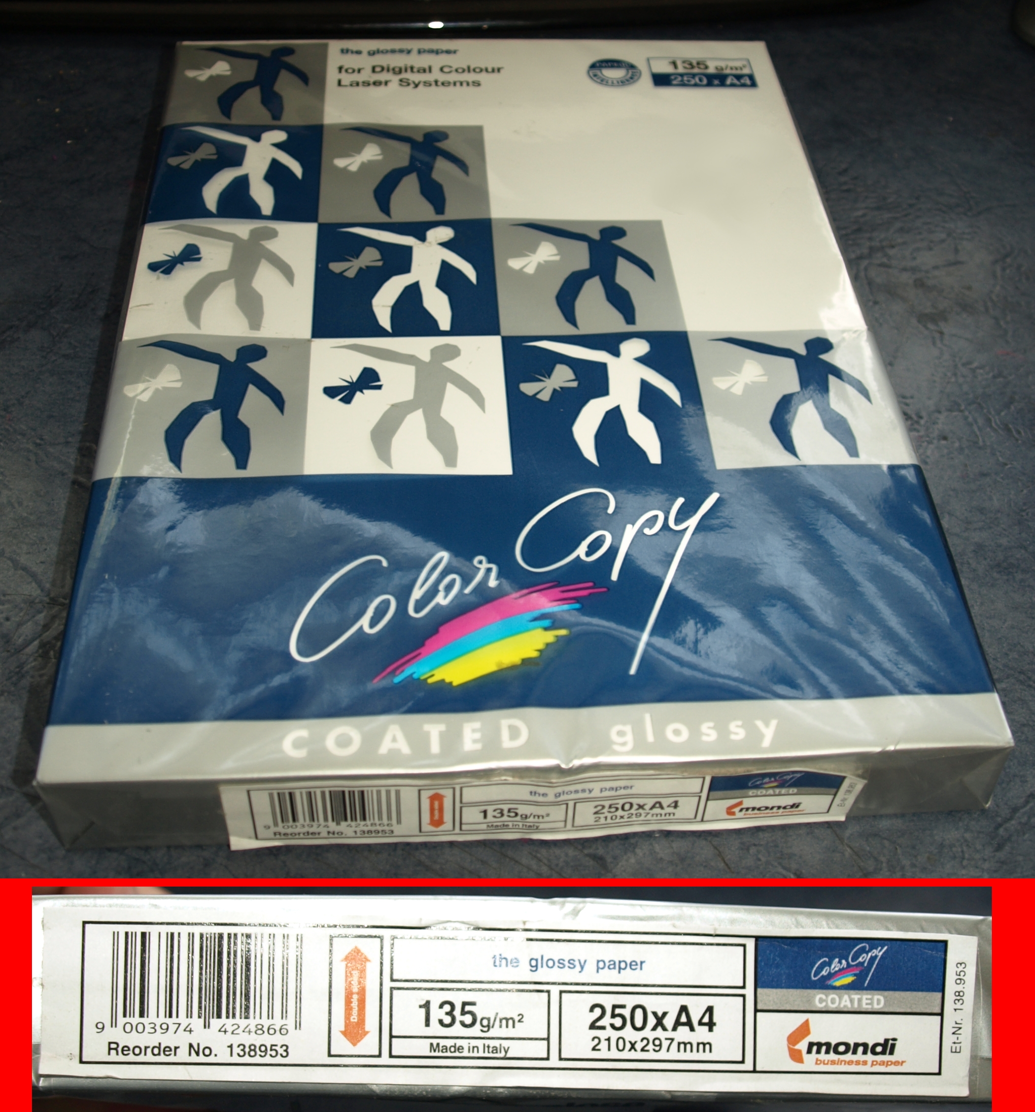
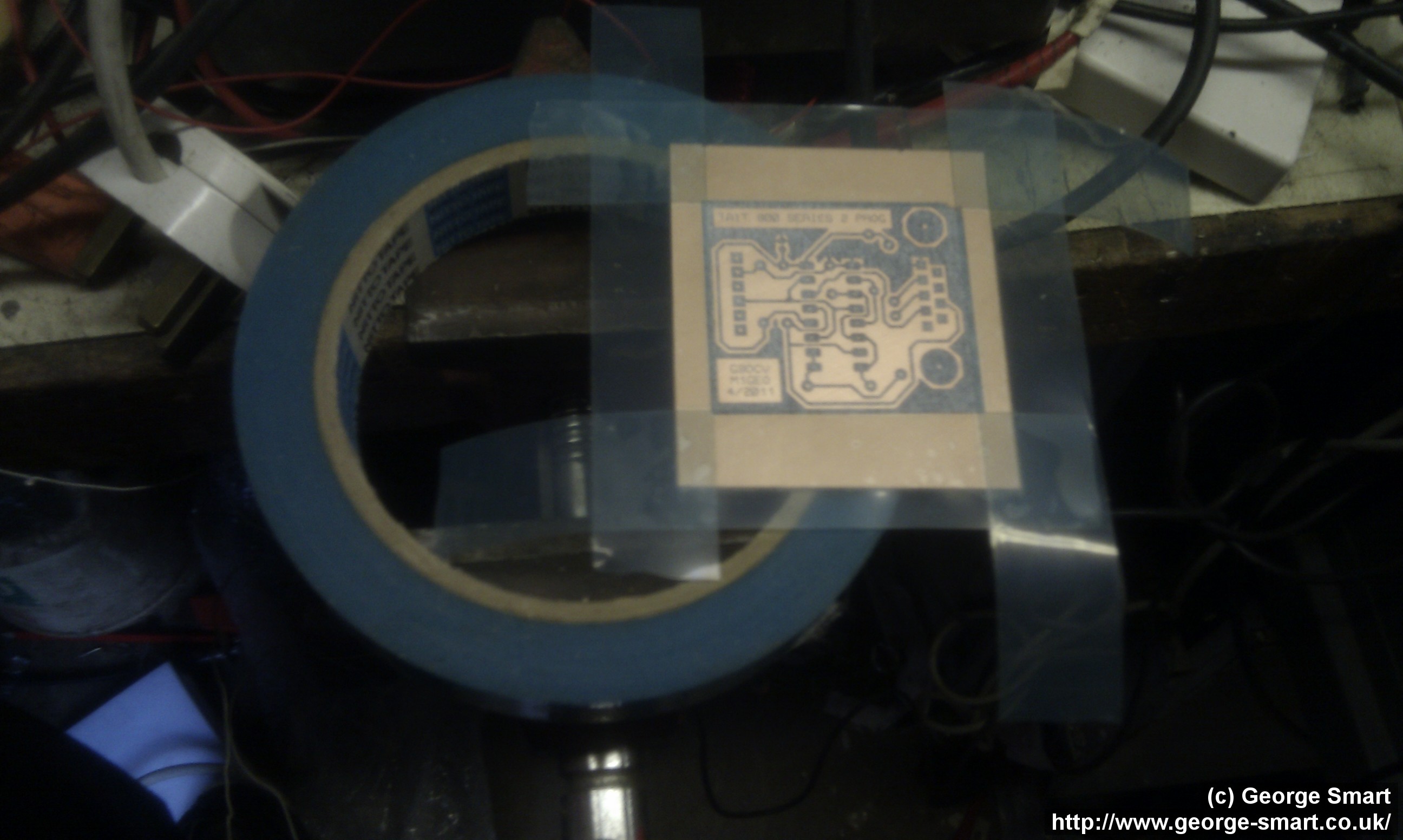
Paper is probably one of the most critical factors in the toner transfer method. You need a method to get the toner to un-bond from the paper. I have taken the approach of using clay-coated paper (usually referred to as glossy paper). This is standard paper coating with a thin clay coating – this gives the paper a shiny white appearance ideal for printing onto. It also makes it ideal to soak in water and get the toner off. I am currently using some mondi paper. It’s 135  and comes in packs of 250 sheets x A4. The image to the right is of a pack of unopened paper (click to enlarge). Some other paper I have found to work well include:
- Maxim/Dallas brochures (sent out to people via post on a fortnightly basis, containing information about their new ICs) – Works well & free/delivered
- Some cheap packs of glossy paper can be found in Tesco, etc.
Avoid plastic glossy paper! It melts… everywhere… so check that before you use it. It took me a good while to un-jam it from the printer’s heater. I just experimented – I didn’t pay much money for the paper and the stuff that didn’t work well for PCB just got used like normal paper.
Preparing the PCB
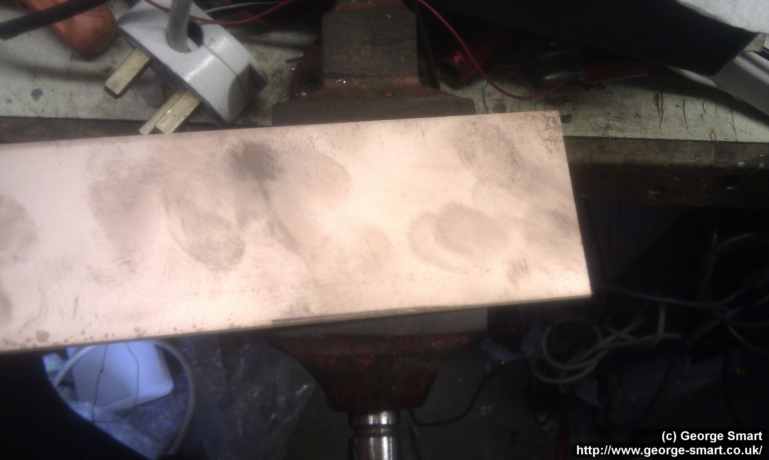
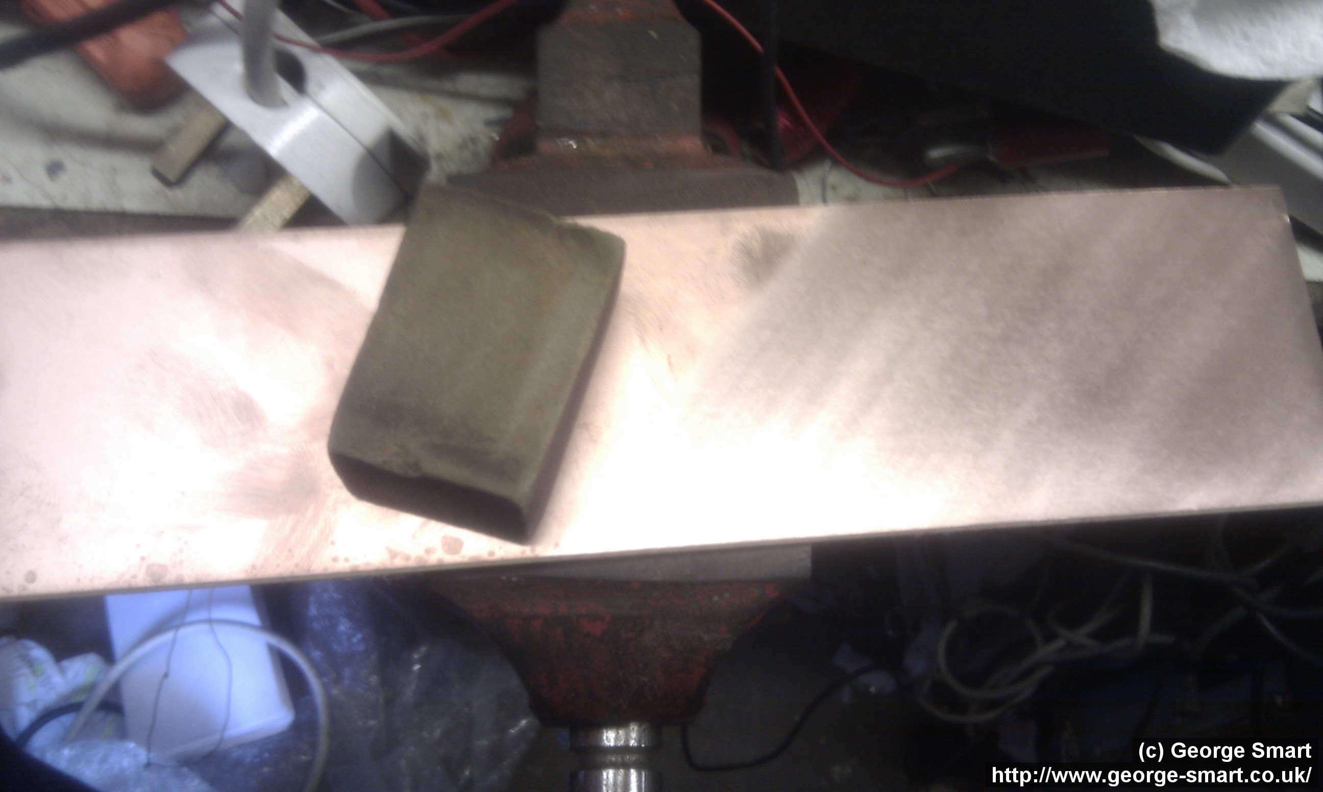
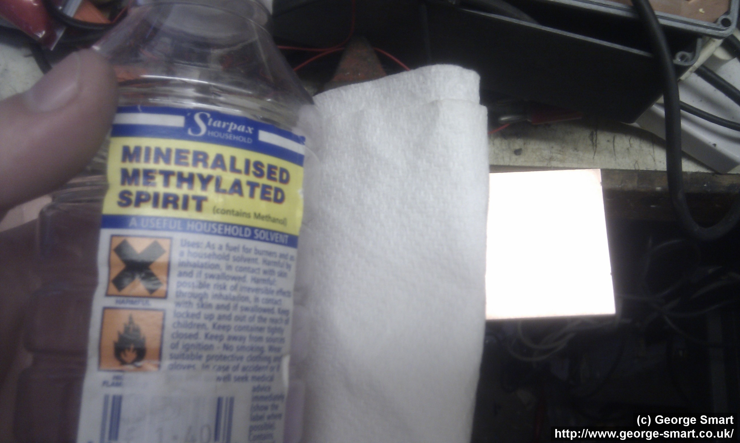
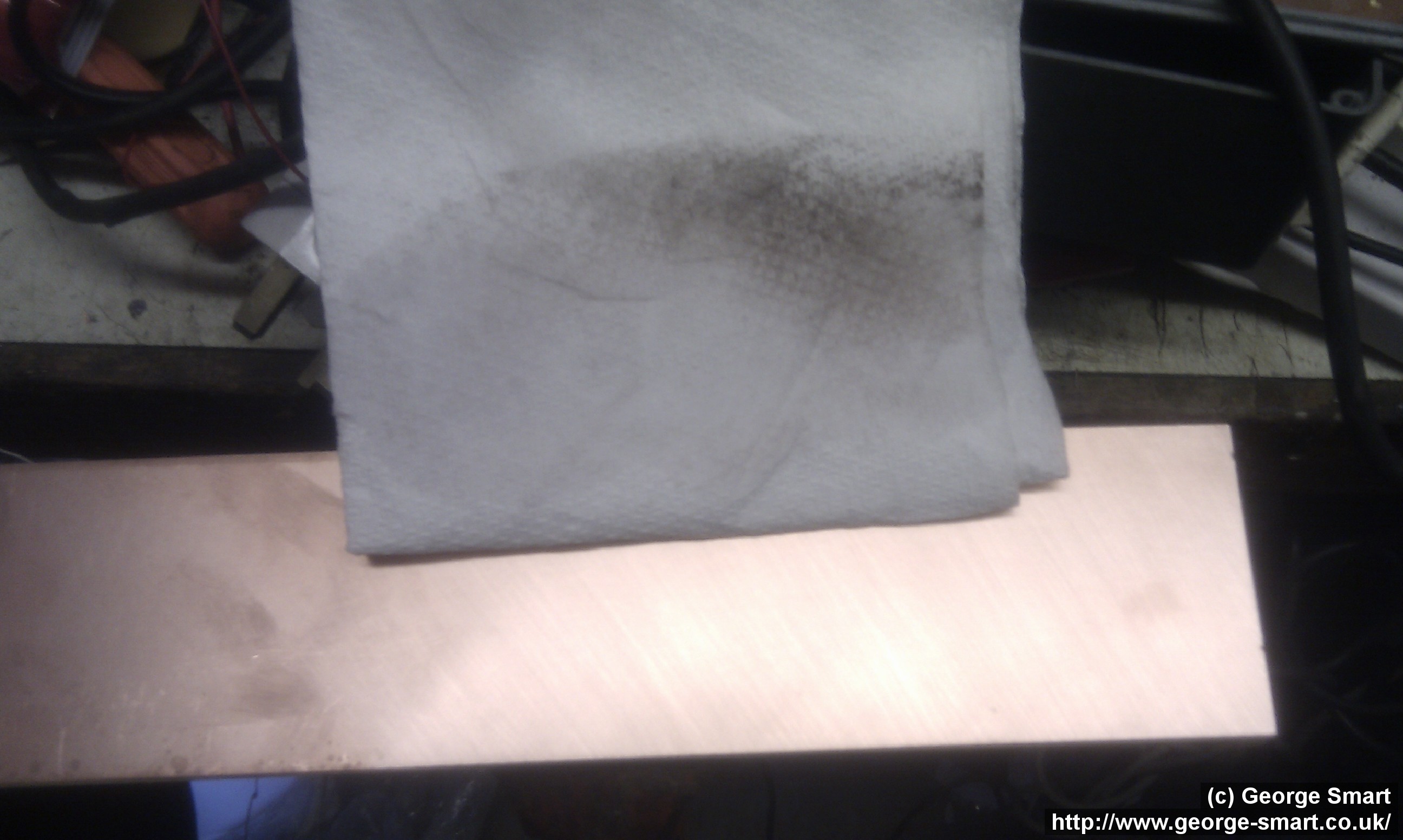
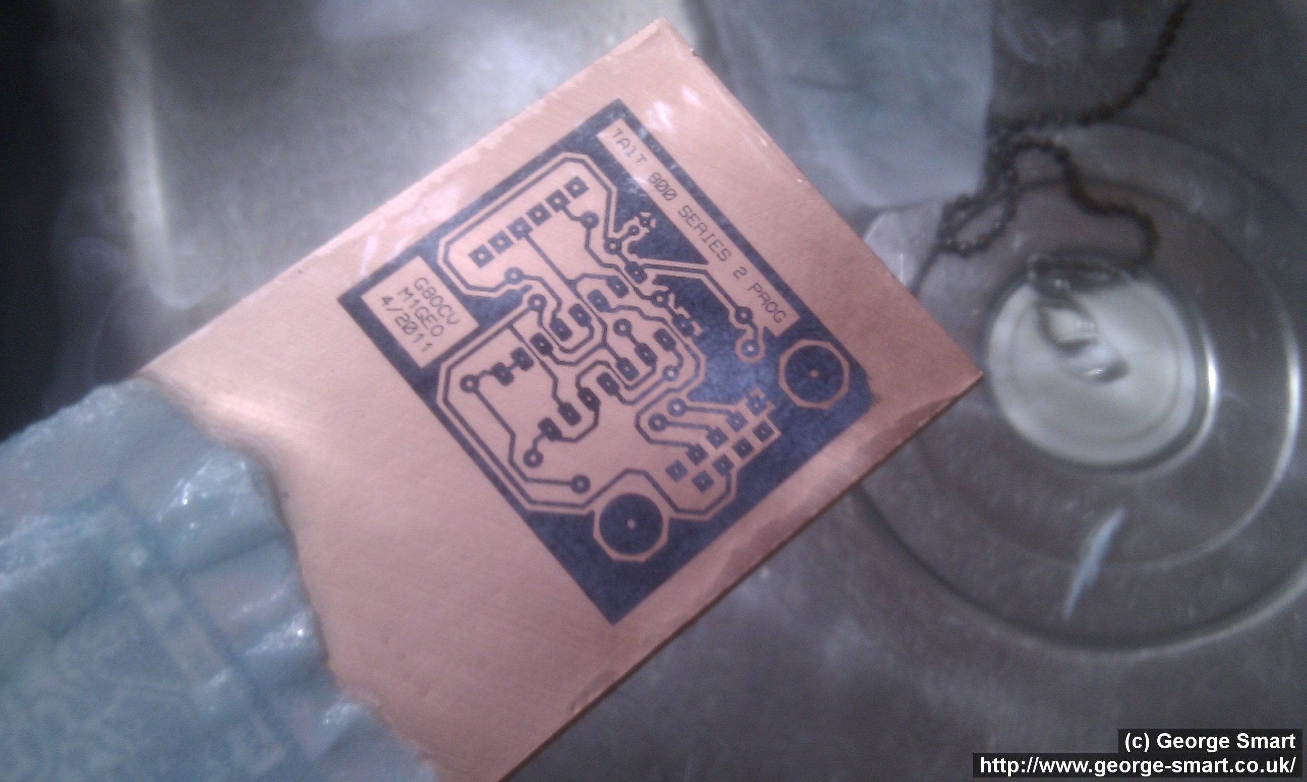
Image 1 shows a strip of PCB – an off-cut from the manufacturing of commercial PCBs. I then use a sanding block (image 2) to get a good, shiny surface on the copper. I then use methylated spirit to remove any sanding dust and grease (image 3) from the surface of the PCB. Don’t touch the PCB after this stage, and if you do, go back and wipe it again (image 4).
 |
 |
 |
 |
| Image 1 | Image 2 | Image 3 | Image 4 |
Click on an image to enlarge
Iron on the Toner
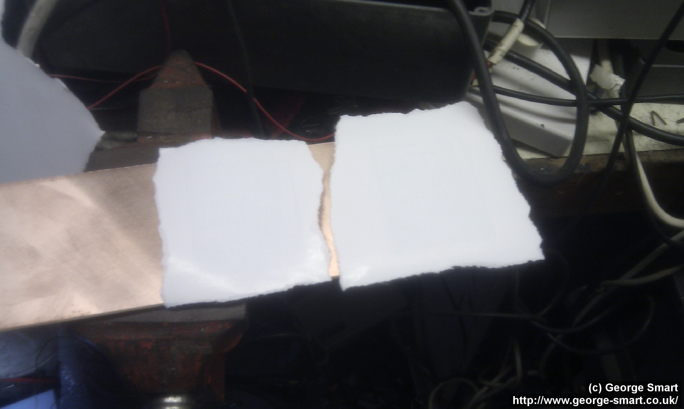
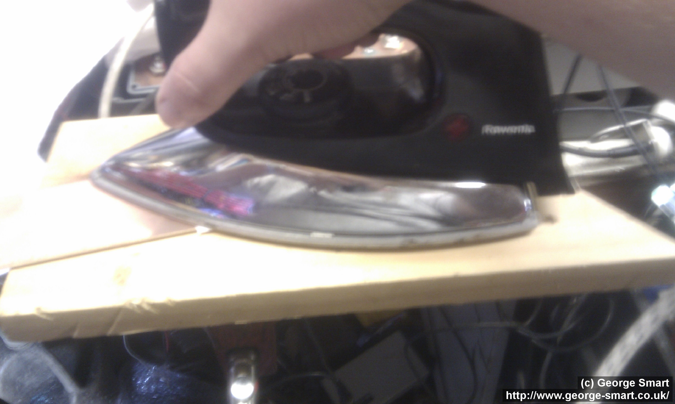
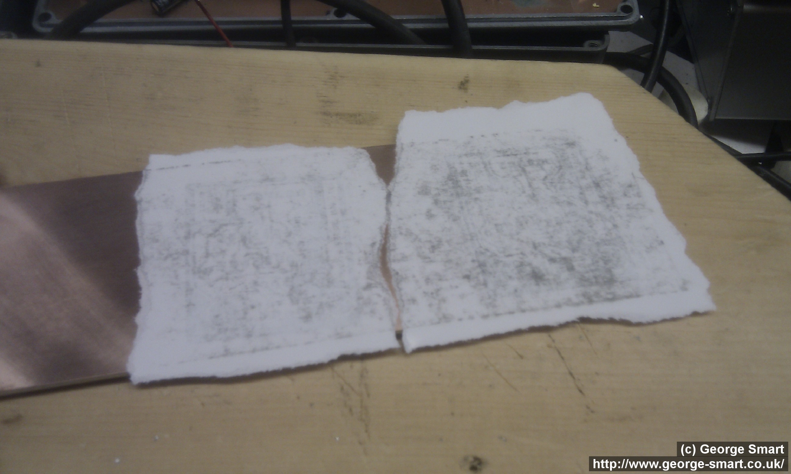
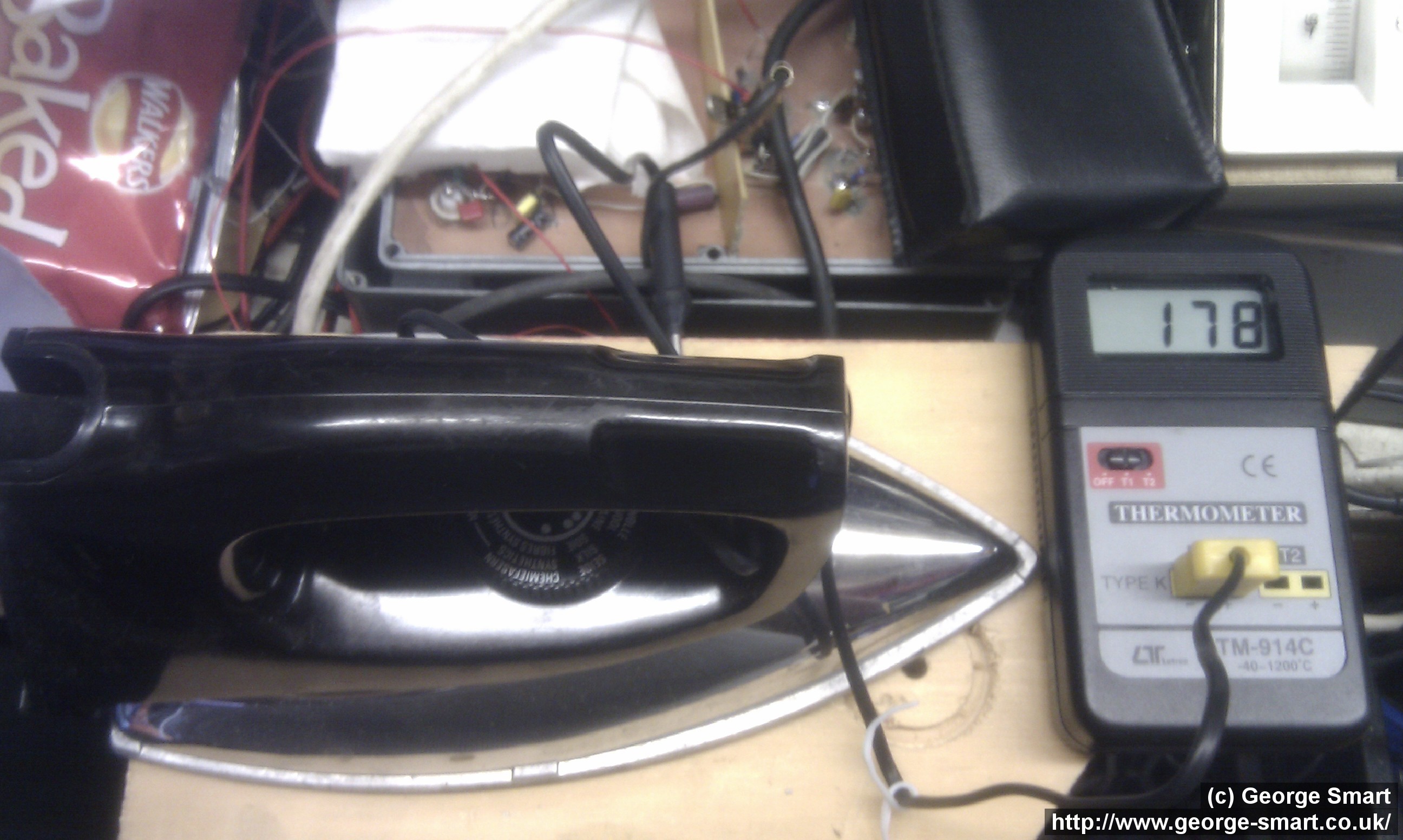
After printing the PCB masks onto your paper, cut (or tear as in image 1) your masks into smaller sections. Image 2 shows how I used an old iron at about 180  C (image 4). You need to make sure that you’ve applied even pressure all over the mask, especially the corners. When you’ve finished, the masks should look something like image 3. Let the masks cool before you play with them.
 |
 |
 |
 |
| Image 1 | Image 2 | Image 3 | Image 4 |
Click on an image to enlarge
= Remove Paper =
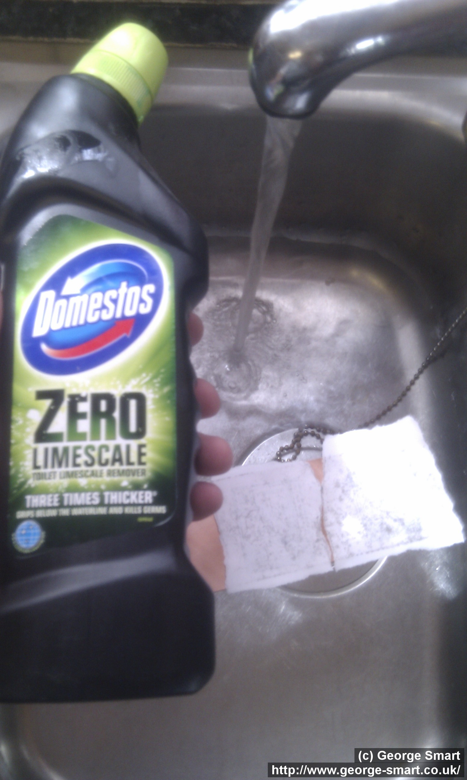
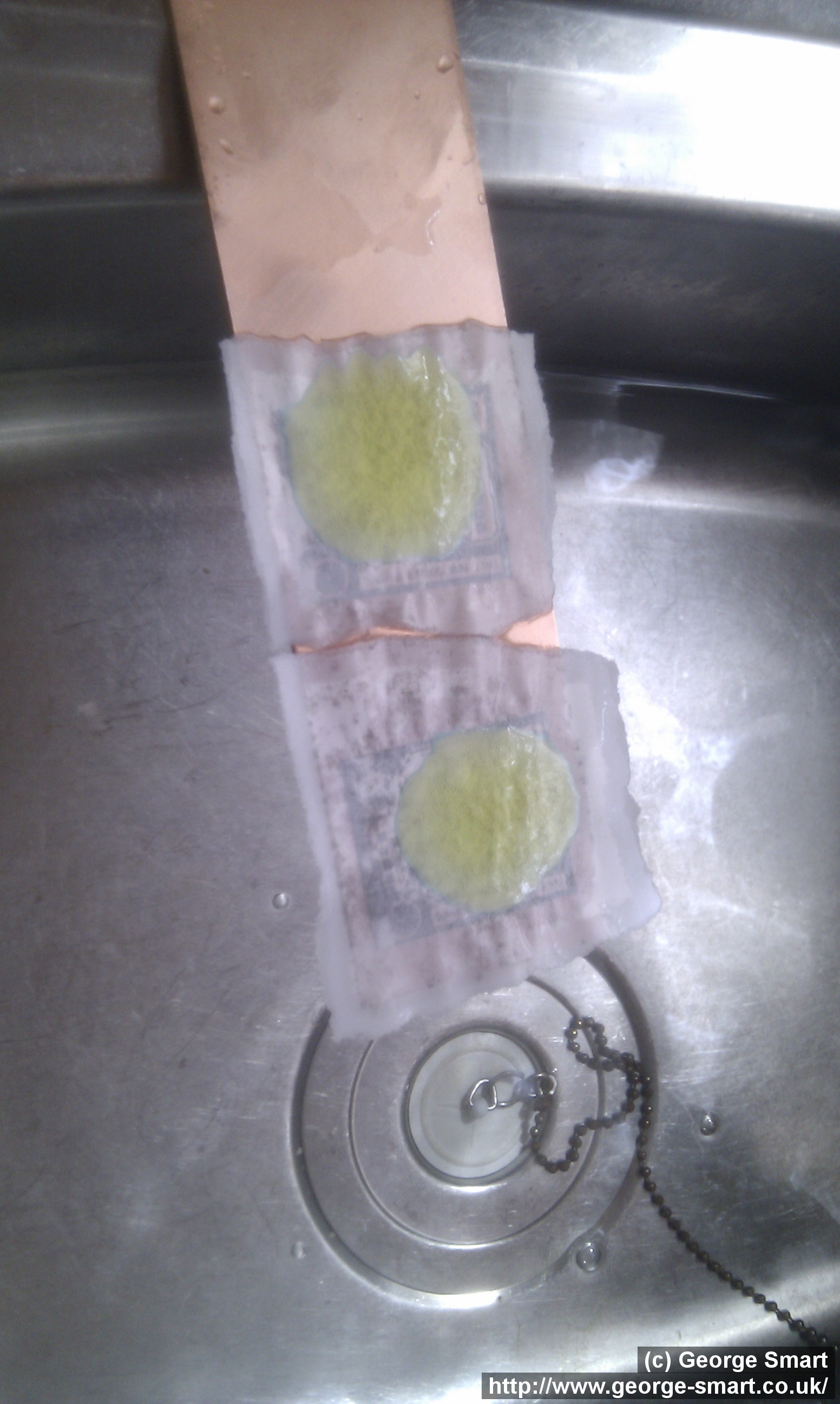
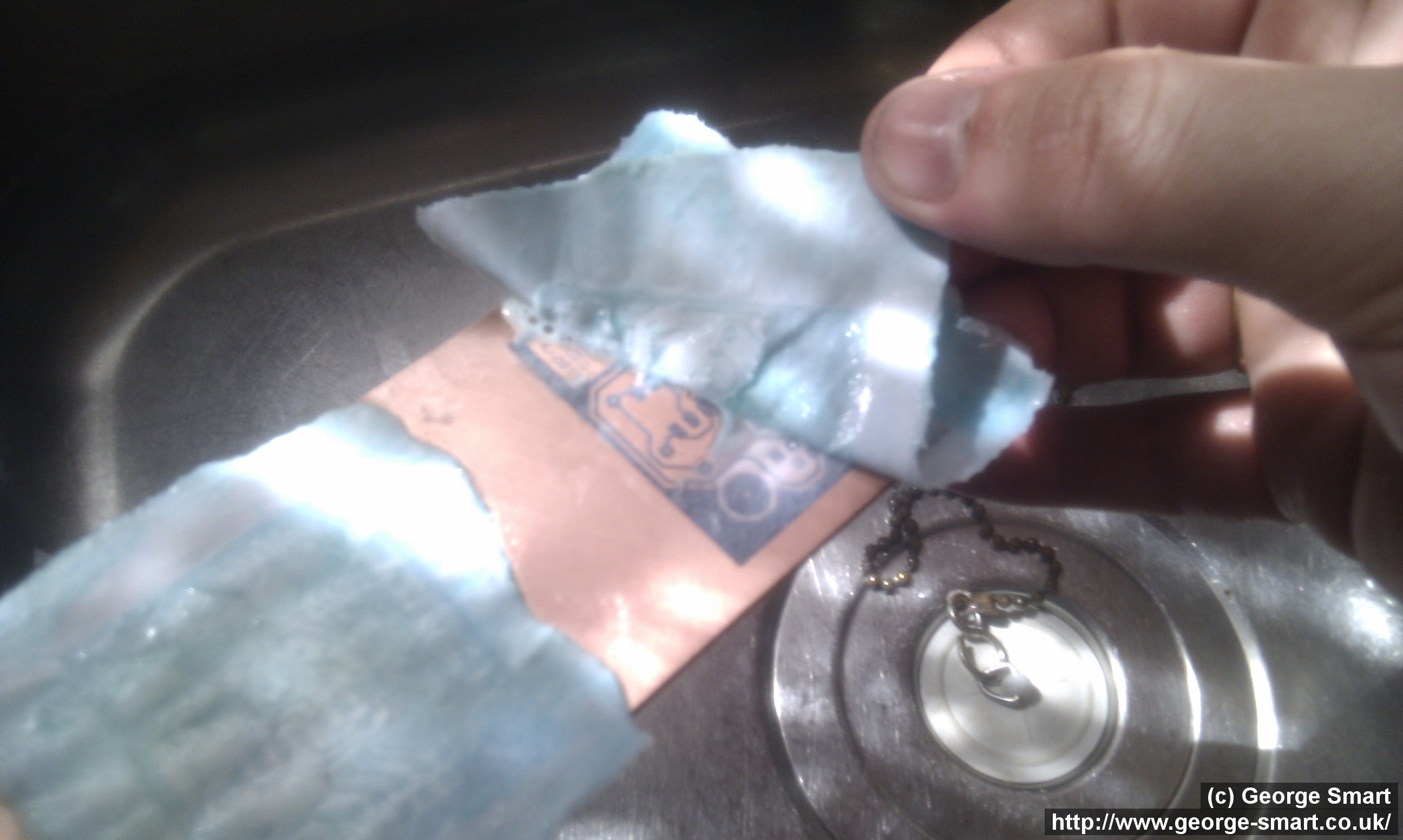
Image 1 shows Domestos Zero Limescale cleaner. Dave Mills, G7UVW found this to work well in breaking paper down. Soak the paper for a few moments before putting a small amount of this cleaner on to the top of the paper (image 2). Rubbing the cleaner around with your finger helps work it into the paper. It only takes a few minutes and you should be able to peel the paper off with your hand, working slowly from one corner (image 3). If any paper or clay is left on the board, you will need to rub your fingers over this area to get the paper fibres off the board. People say this should be done carefully; my approach is that if rubbing it with your fingers makes the toner come off, then it hadn’t properly affixed to the copper. It may be useful to rub the board with some paper fibres you’ve already freed, as this helps to get the small fibres off. You should end up with something like in image 4 – your mask may vary from mine 🙂
 |
 |
 |
 |
| Image 1 | Image 2 | Image 3 | Image 4 |
Click on an image to enlarge
Troubleshooting
It is at this stage you can assess how well it’s going to go. Once you have toner on to your board, it will work. The hard bit is getting the toner onto the board. Below are a few pointers for things that often go wrong:
- Toner comes off with the paper:
- * If all the toner comes off with the paper, and none stays with the board then the iron probably wasn’t hot enough.
- * If patches come off and some stay on, there was either grease on the PCB or you didn’t apply and firm, even, pressure when ironing.
- * The paper should split apart; the clay staying with the toner, the fibre mesh should pull away or break apart with rubbing.
- If toner squidges out and narrow tracks become wider, then you’ve probably got the iron too hot or you’re pushing (far too) hard.
As well as that, be careful not to twist or slide the mask on the copper, as this will twist the mask rendering whatever results as useless.
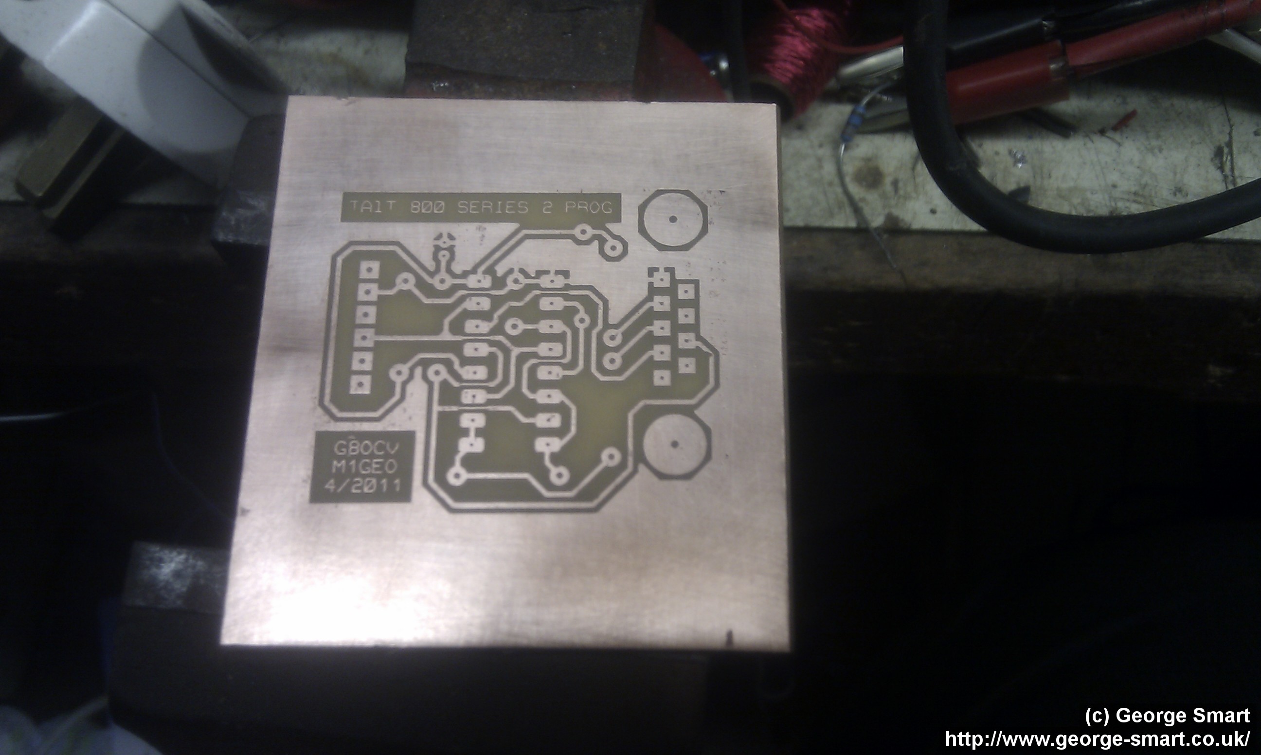
Etch the Board
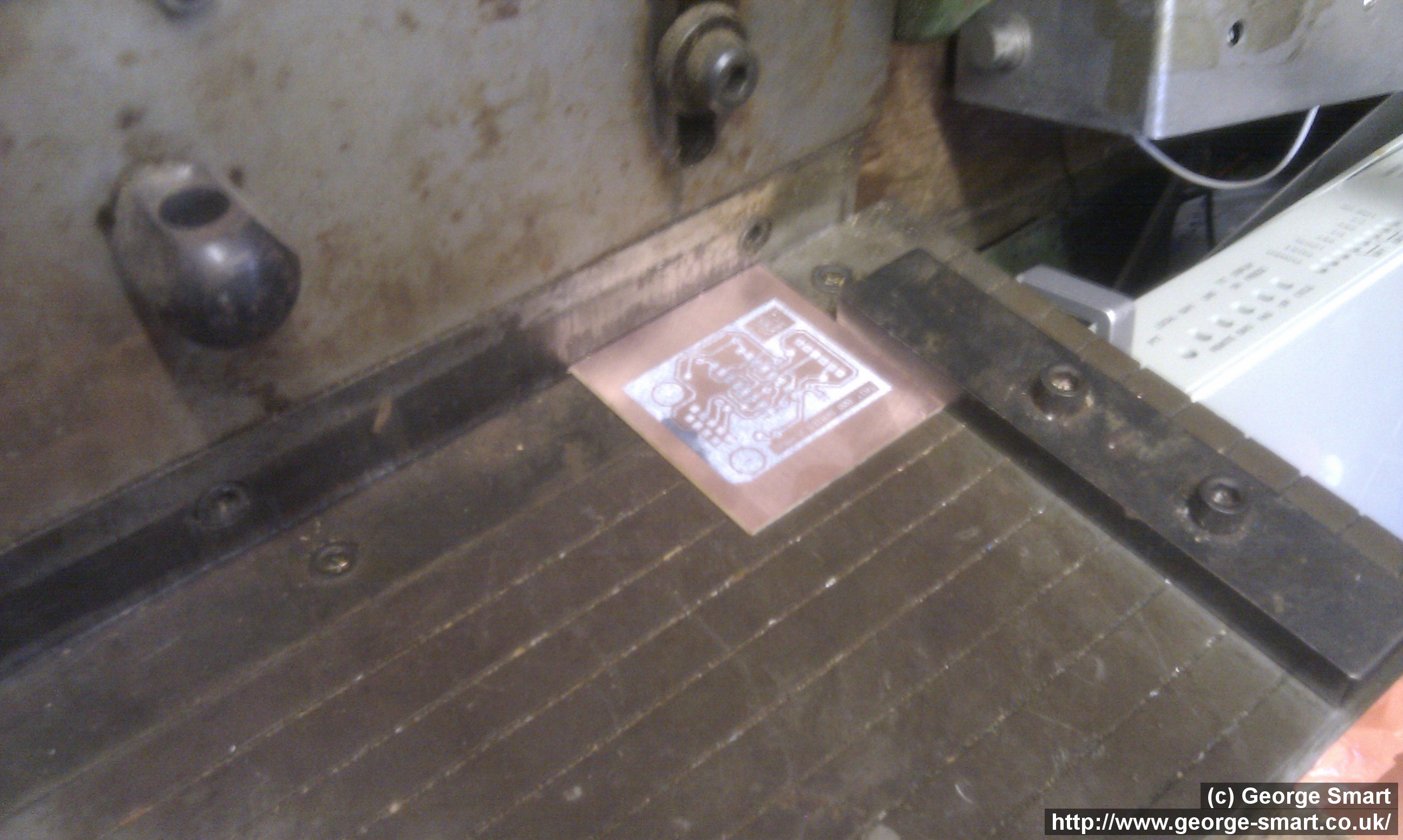
The board was first trimmed to a humane size, using the metal guillotine (image 1). The edges of the board are then masked off with Nitto-Tape, to save the etchant and reduce the time required to etch the board (image 2). Image 3 shows the RS etching tank looking a bit buried and worse of wares. Image 4 shows the completed etched board – cellulose thinners can be used as a solvent for toner.
 |
 |
 |
 |
| Image 1 | Image 2 | Image 3 | Image 4 |
Click on an image to enlarge
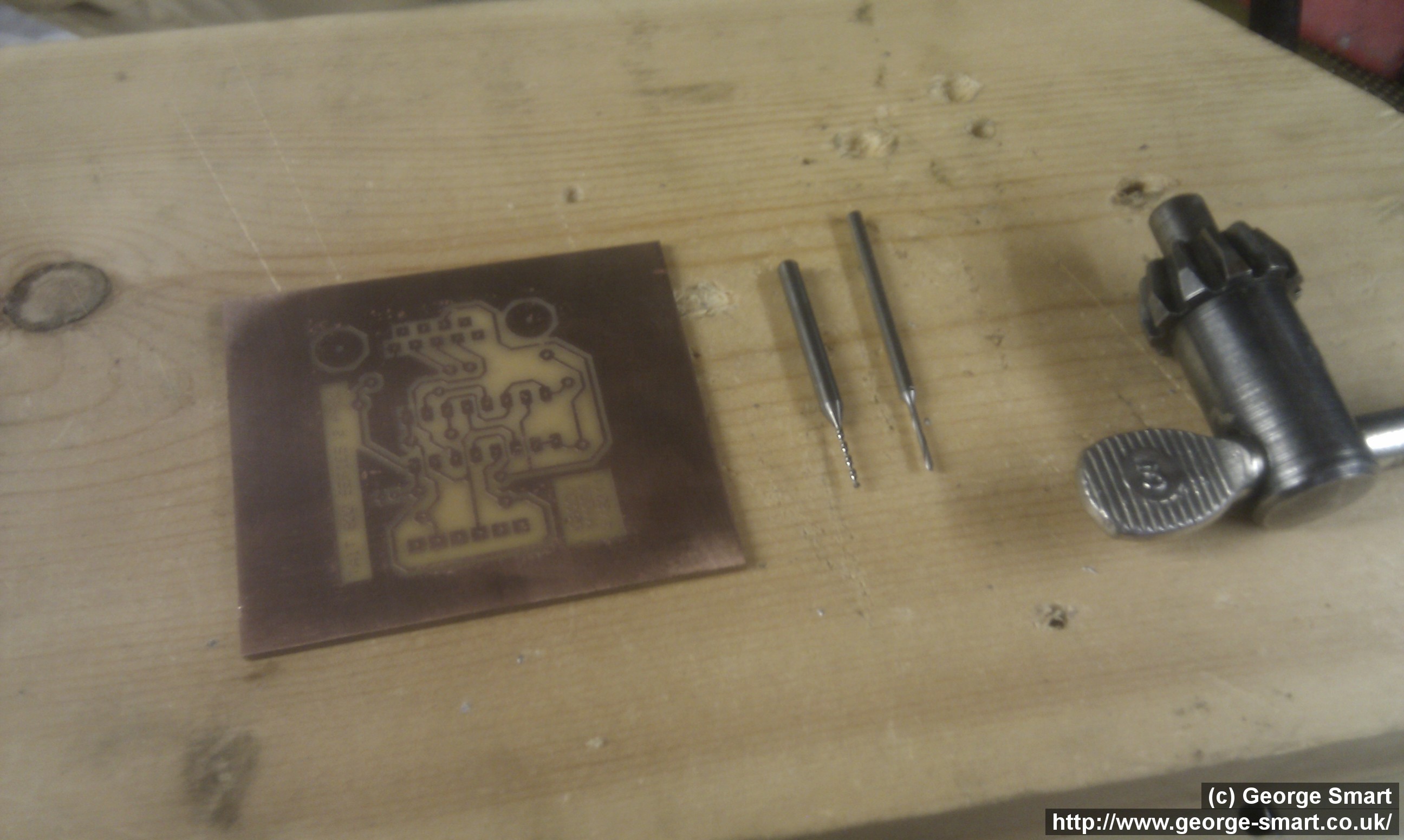
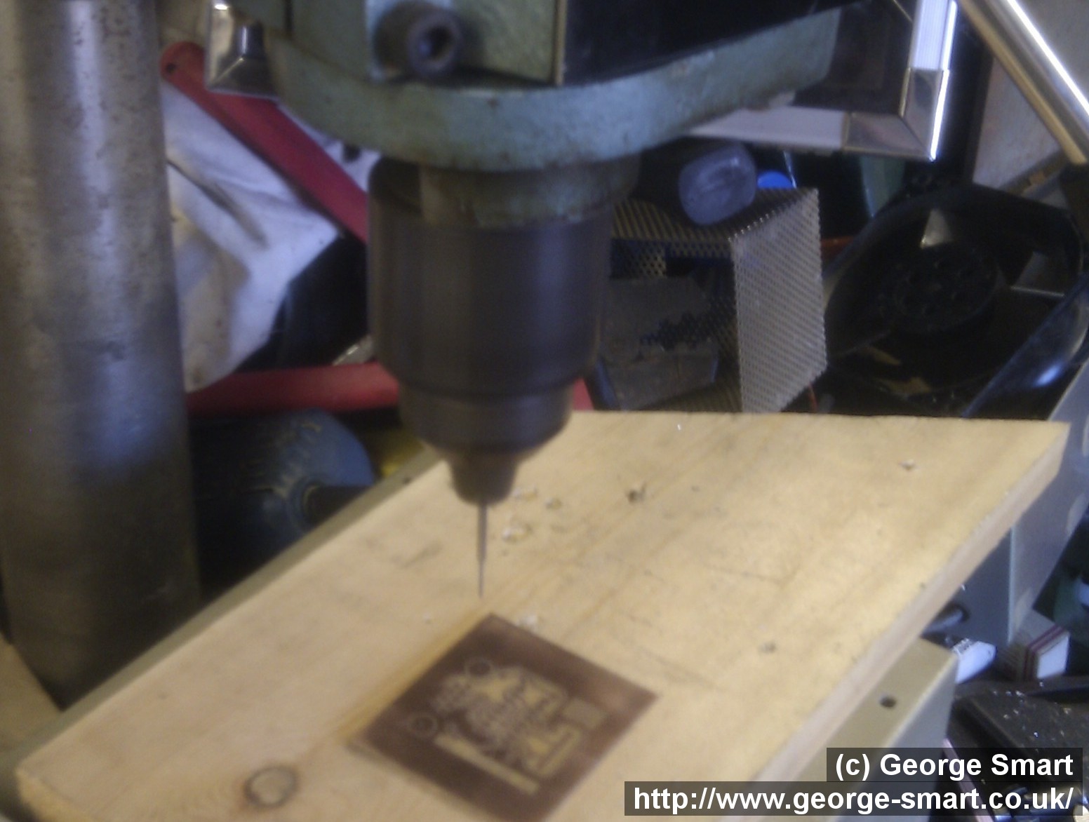
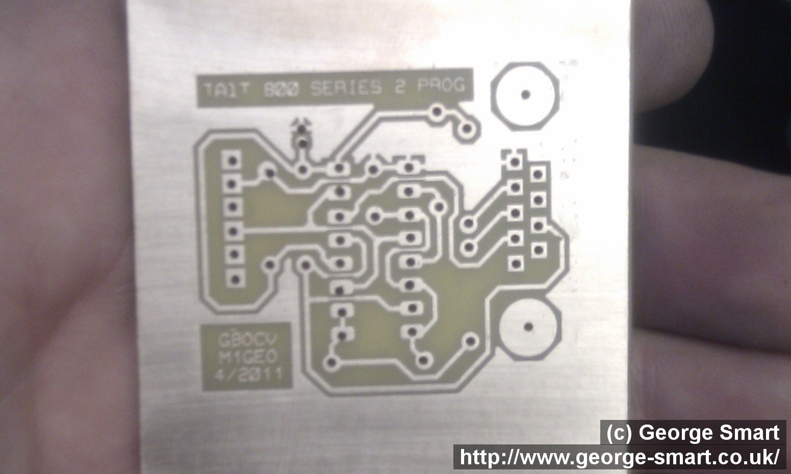
Drill the PCB
Once the board reaches this state, the process is the same as with photo-resist boards. I use a big Meddings pillow drill to drill out PCBs with either a 0.7mm tungsten carbide drill bit or a 1.0mm steel drill bit, depending on the type of board, etc. Image 1 shows the two drills. Tungsten drills are very fragile and break very easily – great benefit comes from using a big (stable/solid) drill with the bit spinning very fast (image 2). The steel drills are much less fragile but don’t drill well through fibre-glass board – steel drills are suited to paper bonded board (the white stuff you often see). Image 3 shows the completed board, drilled with 1mm steel drill. You will notice that some of the drill holes are slightly off. Never mind!
 |
 |
 |
| Image 1 | Image 2 | Image 3 |
Click on an image to enlarge
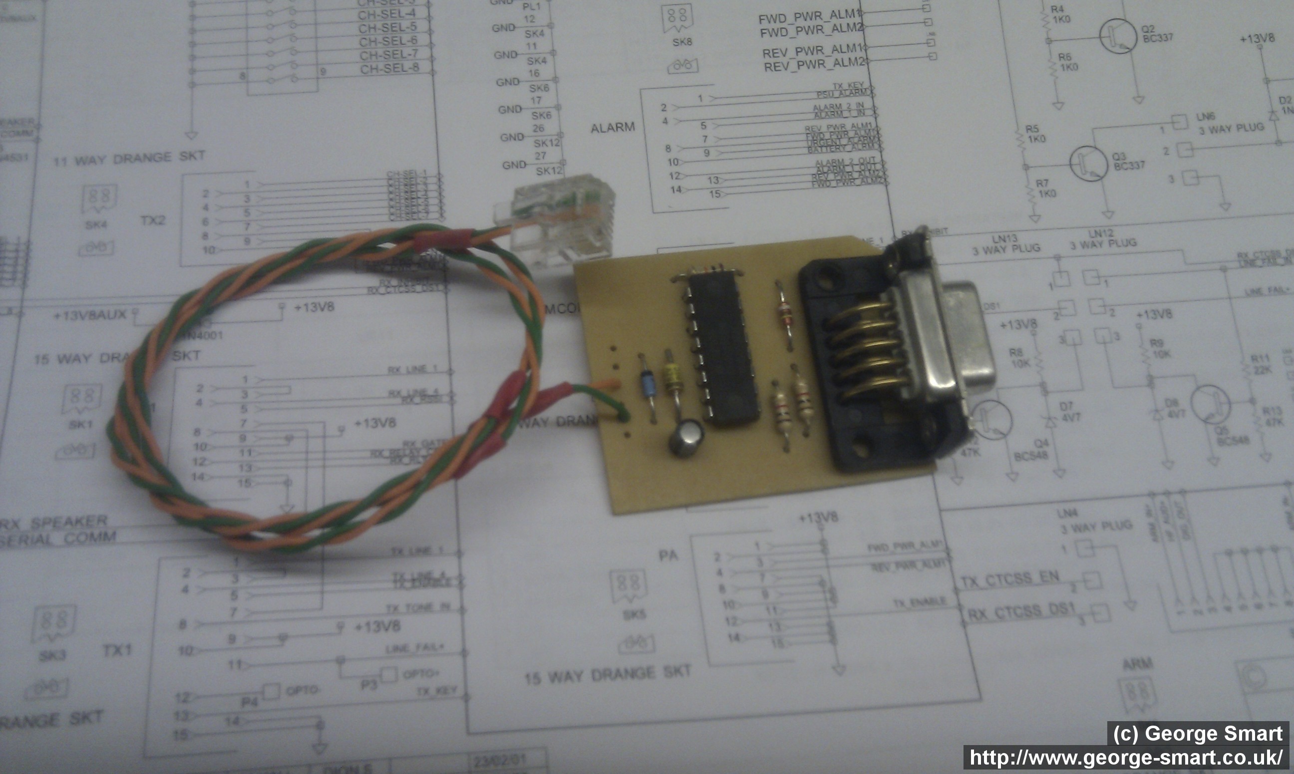
Assemble the PCB
Then I soldered on the components and was pleased that the board worked first time 🙂 If you are actually interested in the board shown here (It’s an interface to program Tait T800 Series 2 Repeaters, then check out my Tait T800 Series II Repeater page.
 |
| Image 1 |
Click on an image to enlarge