
Introduction
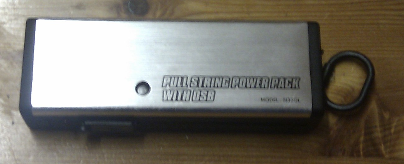
While getting some parts in a local Maplin Electronics store, I decided to have a wander around. Aaron Brown calls this looking for inspiration. That is exactly what I found. I was looking in despair at the solar USB chargers, etc. when I come across a pull string USB charger. It had a nice brushed aluminium case, with connectors nicely mounted on both ends. The best part was that it was £2.99. My mind instantly thought of the Battery Phone Charger.
I read the back of the box, where it explained that I could pull the cord on the device to charge an internal 3.7 volt, 650 milli-amp/hour (mAh) battery. It also had a mini-USB connector where it could be connected to a PC to charge via USB. My plan was to remove the pull string mechanism and replace it with some extra battery cells. I would use some Ni-Cd batteries because of their higher capacities. Each Ni-Cd cell is 1.2 volts. 3 of these cells in series would give me 3.6 volts – close enough to the 3.7 volts of the existing lithium cell. Only these Ni-Cd’s were 3000mAh instead of the 650mAh.
The device in question is the Maplin N32GL: Pull String Power Pack with USB. For £2.99, I decided that it was worth the chance, I bought 2 (one for me, and another for Aaron Brown). We got back to the house and opened up our goodies to start the conversion. Here’s what is (was) inside:
Inside
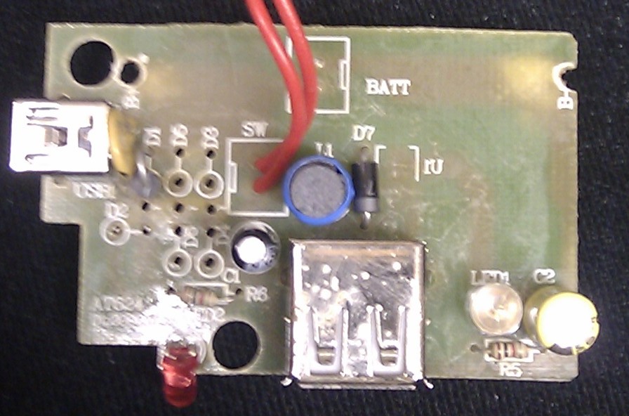
The inside of the device is not very impressive – I am not sure what I was expecting, but there really was very little on the PCB at all.
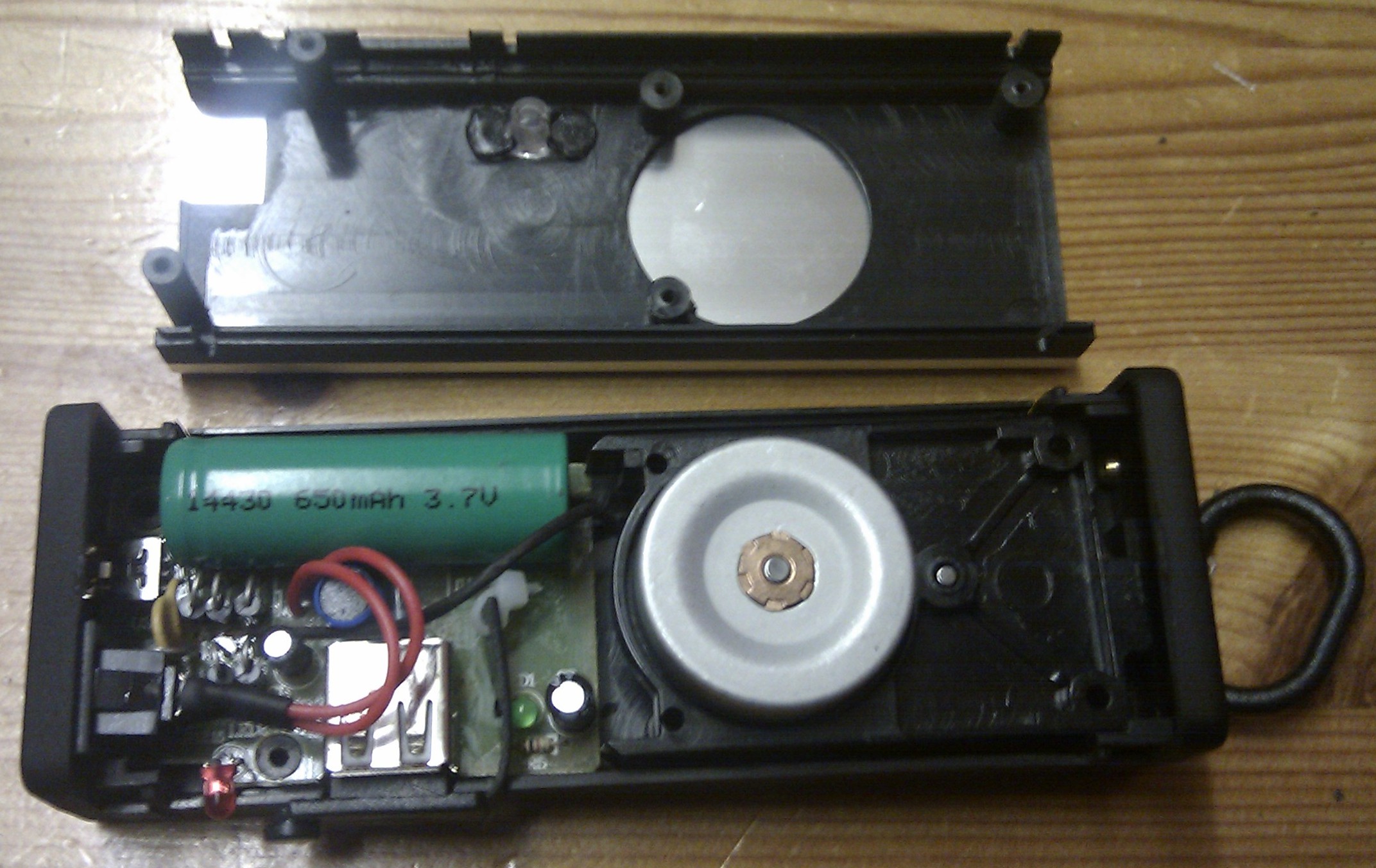
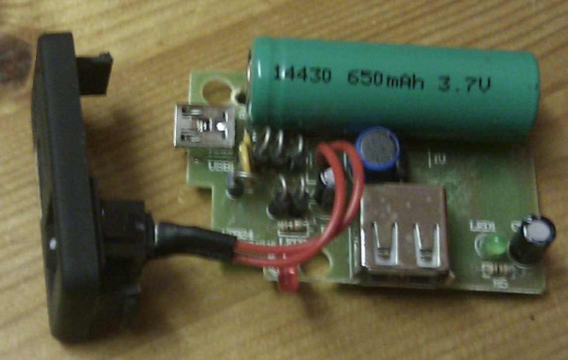
The right of the device is taken up with the winder mechanism, while the left houses the electronics: The green cylinder is (maybe obviously) the battery; below that, the PCB housing some diodes for the rectification of the (3-phase) winder output, and a BAU8C switching regulator.
(Click on an image to enlarge it)
 |
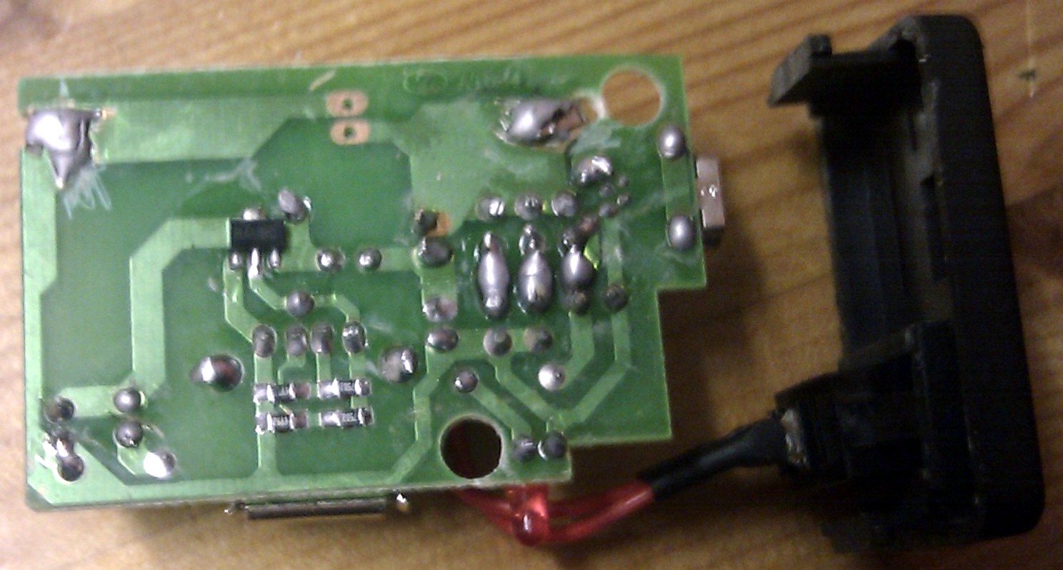 |
| Component Side PCB | Solder Side PCB |
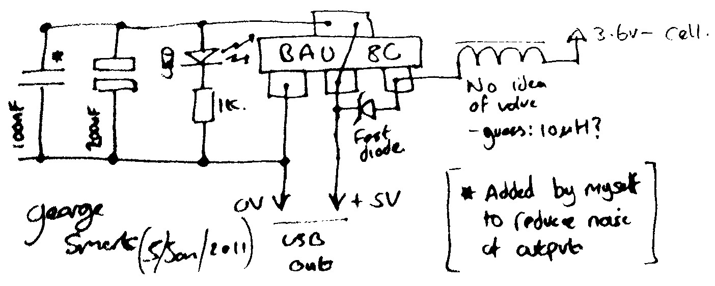
Schematics
The USB input side of the schematic was easy to work out, as it is just a simple arrangement of diodes used for: (A) full wave rectification of the 3-phase winder generator, and; (B) voltage drop from the 5 volt USB to the 3.7 volt cell (along with a resistor). The hard bit to understand was the switching regulator. In practise these are not too hard to understand (see Wikipedia’s Boost Converter page). However this device uses a BAU8C. A quick Google for BAU8C returns nothing of any use. I was looking for a datasheet, or even some typical circuits or schematics using them. Nothing. So here is the best I can offer, based on how mine appears to work.
Butchery
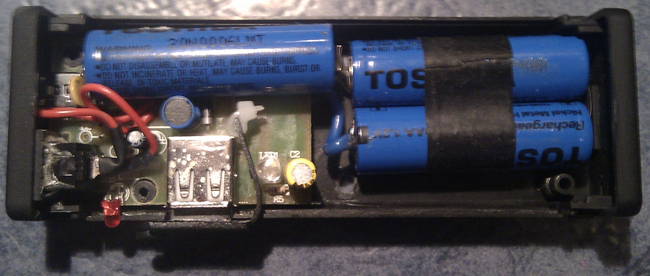
I decided to rip out the winder mechanism as I was never going to use it. I would need the space for extra batteries! As mentioned in the introduction, I would swap out the 3.7 volt lithium cell for 3 NiMH cells in series, giving me 3.6 volts ( ). This should be close enough. I also removed a lot of the un-required diodes from the PCB so I could see what was going on.
(Click on an image to enlarge it)
|
 |
| Original PCB | Revised PCB |
Next I added the cells. I decided to use Nickel-metal Hydride cells, for two reasons: (1) They are much higher capacity for a given size and are fairly cheap, and; (2) I had some already. The cells I used were from an old laptop battery. I decided to use these because they were already connected together in series with metal tabs. These are a lot easier to solder to than the cells themselves, so I went with these. Also, the larger 3000 mAh cells do not belong to me, so I couldn’t really solder (deface) to them. I then soldered a thick wire on to the end two cells, and soldered the new battery on to the PCB.
Testing
I have tested a couple of things here. The first test looks at the output of the device on a scope. The second test looks at the power supplied and at currents and voltages.
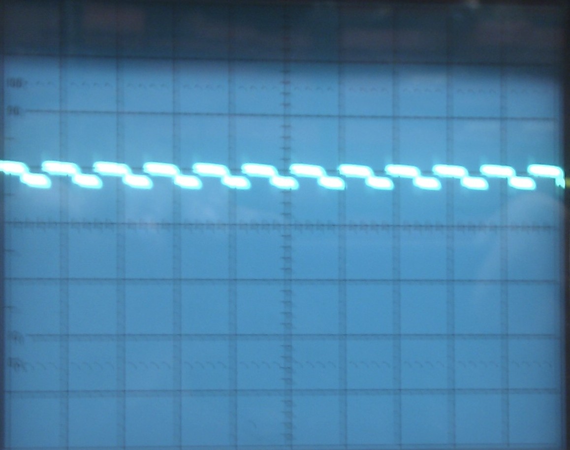
Output Noise
I wanted to look at the output both with and without a load on it, before and after my modifications. On these scope images, the bottom line of the scope is 0 volts DC, and the scope is set to 1 volt per division. The modifications to the output included adding a 100nF capacitor to remove the high frequency switching noise and to chance the 100uF smoothing capacitor for a 220uF capacitor. This smooths some of the pulses under load, and increases the overall voltage – a larger capacitor would further smooth this out but it also leads to deteriorated regulation.
| Before Modifications | After Modifications | |
| Unloaded Output | 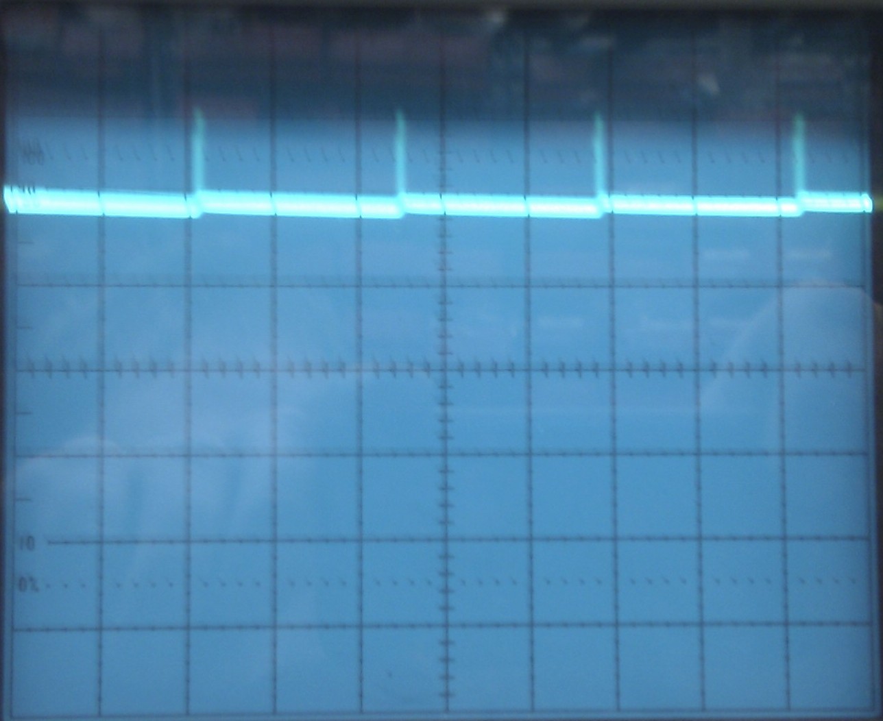 |
 |
| Output Loaded at 500mA | 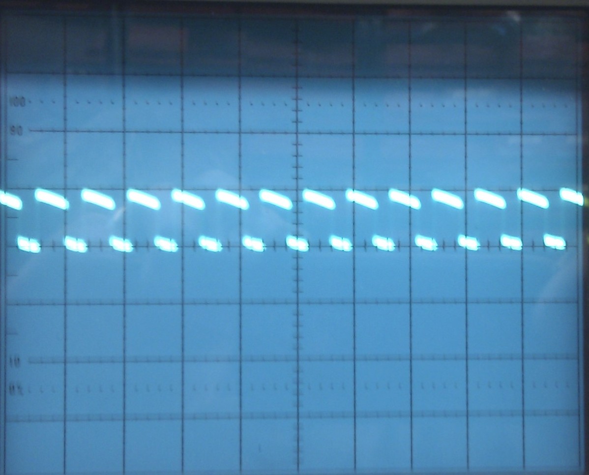 |
 |
(Click on an image to enlarge it)
Power Output
I also decided to see how well the device I modified compared to the original device. I left them both on charge (via USB) all night, totalling a good 7 hours. My test was simple: The device claimed it could supply 500mA at 5 volts. A  resistor would draw 500 mA at 5 volts.
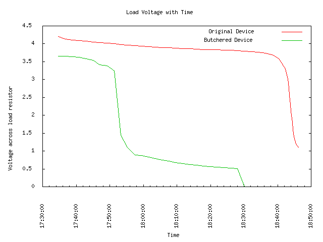
From this graph you can clearly see that the original device is much better. The low output voltage is due to the thin wires inside the USB cable. The voltages here are directly across the resistor, and so are the load voltage. At 500mA, we were dropping 1 volt over the wires. The BAU8C regulator aims to provide 5.5 volts.
Why So Crap?
So, as you can see from the above graphs, my modified device was rubbish compared to the original device. After a little thought, I realised why: The charging circuit couldn’t supply a high enough voltage to charge the 3 NiMH cells. Various sources, mentioned below, detail the charging of NiMH cells. Typically, a NiMH cell is charged with a voltage of around 1.6 volts. There are different schemes of charging batteries. The scheme originally was a cross between trickle charge and a kind of fast charge – not recommended!
When the cells were changed for the more demanding NiMH cells, there simply wasn’t a high enough voltage to charge the three cells in series. When they were all flat, the cell with the lowest voltage (determined by manufacturing tolerances, etc) would charge first. The others would charge a little too. Once the first cell is charged, there is a lower voltage for the other two cells – they charge at a lower current, requiring much longer to reach full charge. Once two of the cells were charged, the third cell would take even longer to reach full charge.
In my device, there simply wasn’t enough potential difference to allow more than one cell to charge, so only one cell ever did. When performing the tests, the one charged cell provided as much power as possible, until it was discharged. The flat cells detract from the energy supplied due to a process called Polarity Reversal.
The Fix?
Aaron suggested that I used a lithium cell with a higher capacity instead of a chain of NiMH cells. I found an old Nokia BL-5J battery pack I had for an old mobile phone. I repeated the power test for the Lithium battery.
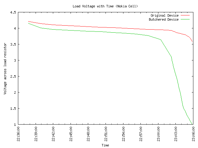
This is, again, worse than the original 650 mAh cell. This time I noted that the reason the battery was never used in my mobile phone was because the battery only lasted about 2 hours in the mobile phone. While the genuine Nokia battery was 1350 mAh, I have large reason to doubt this Chinese copy of the BL-5J is. The Fix? No. 🙁
Sources
- [1] Batteries
::(http://homepages.which.net/~paul.hills/Batteries/BatteriesBody.html)
::Taken on 5/Jan/2011 at 19:31 BST
- [2] Nickel-metal hydride battery : Wikipedia
::(http://en.wikipedia.org/wiki/Nickel-metal_hydride_battery)
::Taken on 5/Jan/2011 at 19:34 BST
- [3] NiCd Battery Charger
::(http://www.angelfire.com/electronic/hayles/charge1.html)
::Taken on 5/Jan/2011 at 19:31 BST