
This short experiment was inspired by a talk at the RSGB Convention 2016, given by Paul M0XPD of “Shack Nasties” fame.
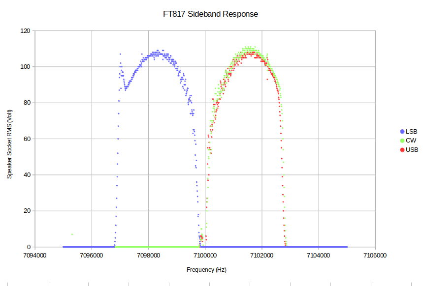
Paul presented, amongst other things, the idea of using a DDS to sweep the RF input of a receiver and monitor the AF output. Plotting the RMS voltage of the output vs the input frequency shows the receiver filter shape:
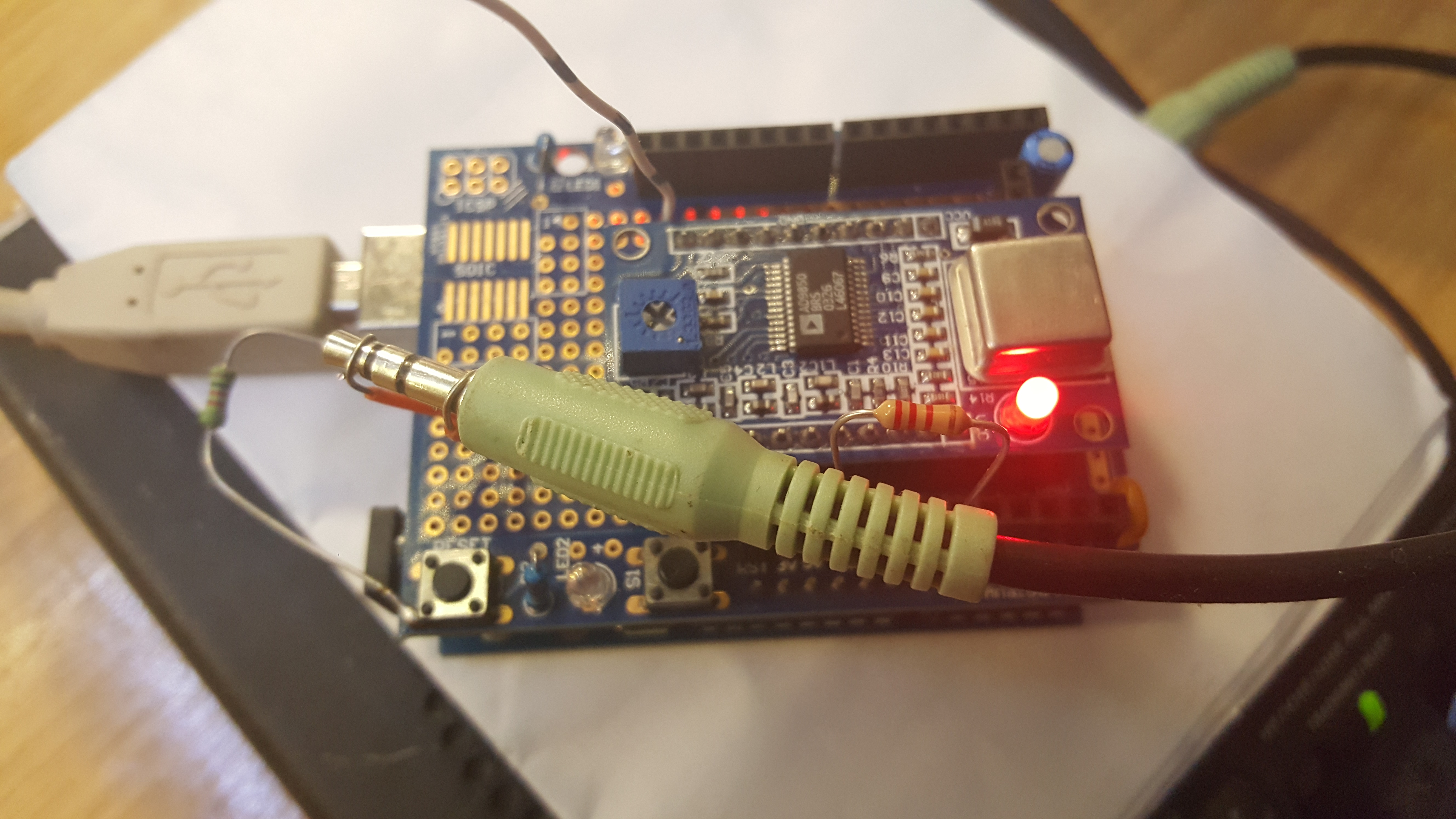
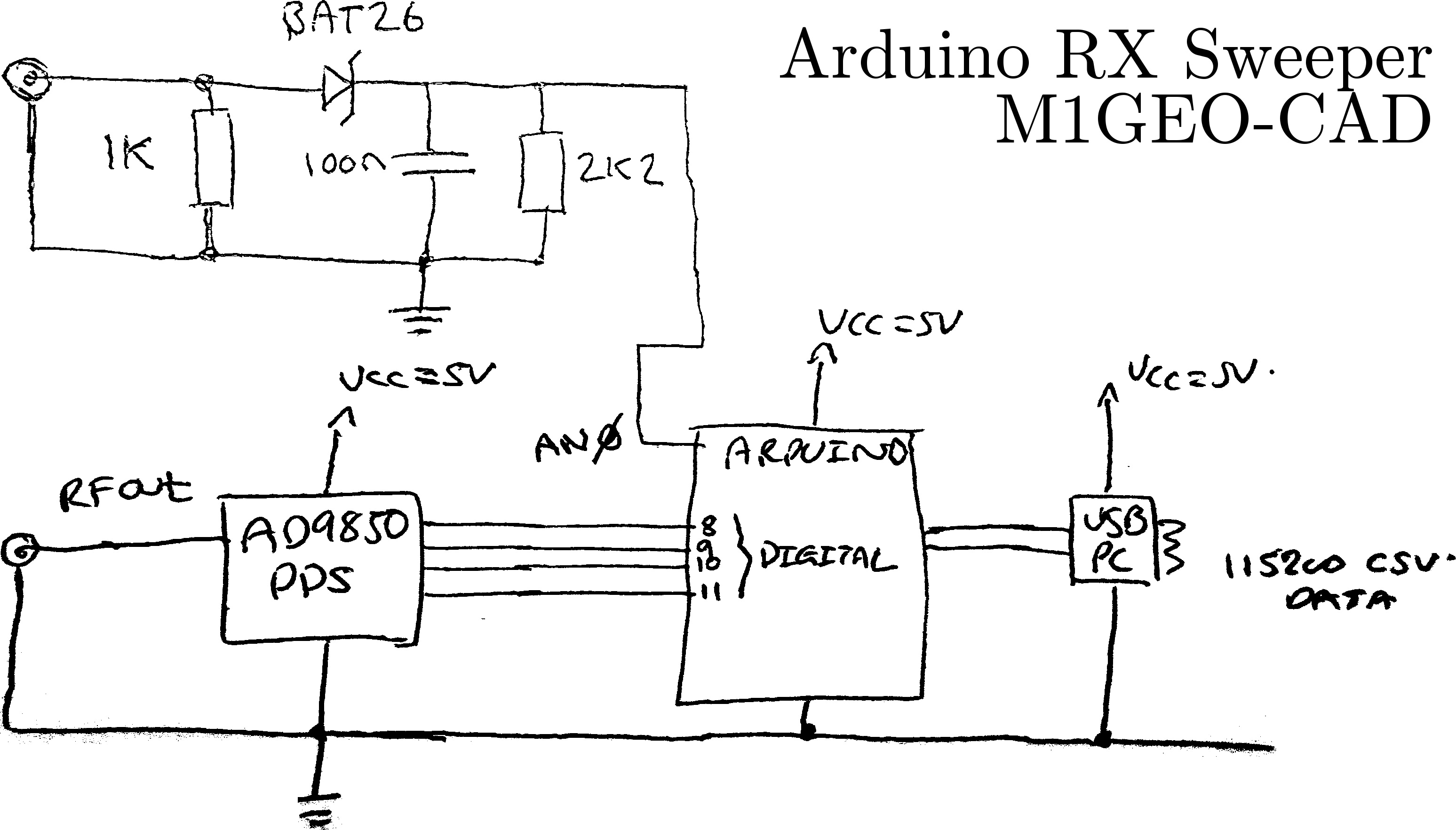
An Arduino did the work, with the USB connection returning results back for plotting. An AD9850 was used as the DDS RF source, and a Schottky diode detector was used to convert the audio AC to a DC value to be read by the Arduino ADC.
I will experiment a bit more with this when I get the time. I’d like to play with a radio that has DSP and look at the filter shapes a little more.
Regarding the FT817, I hadn’t realised it has only one filter by default; the CW goes through the same SSB filter; hence it having the same shape in the plot above. I have no idea why there is a lump on the side of the LSB filter. This is always observable.