Tag Archives: 144 mhz

Some VHF Tinkering

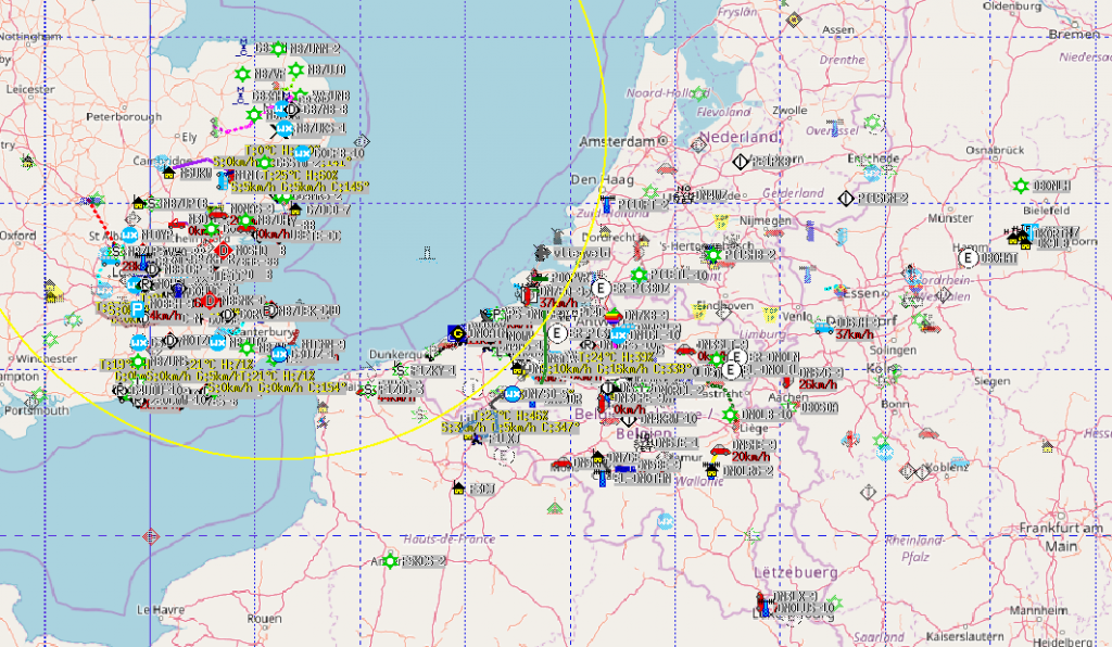
On the way home from work on Friday, my attention was brought to my mobile APRS setup, which was showing received callsigns from Germany, Netherlands, Belgium and France. Once home I decided to connect up my KAM KPC-9612+ TNC to an old Kenwood PMR and see what I heard. The antenna is just a loft-mounted Diamond V-2000, so nothing fancy. About 1 metre of RG58 into the radio. The map is pretty impressive, showing what good conditions were around on VHF at the time. The orange circle shows the ALOHA circle (local reliable APRS network size) – more here – basically the area to which your transmissions would normally be in contention with.


My usual small station EME setup consists of two 9 element DK7ZB Yagi’s bayed at 13 metres. Combined with a Yaseu G5400 Az/El, K3NG’s Arduino rotator interface and YO3SMU’s PstRotator, this is a reasonable attempt at a small station EME setup. Of course you can do it with less, but, it becomes somewhat laborious. With the moon tracking facility of PstRotator, I can set up once, and allow the software to keep the antennas pointing in the correct direction.

The antennas look like this:
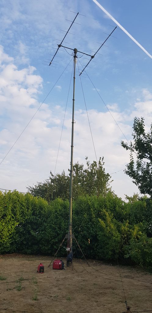
At least we don’t have neighbours!

In the shack, I used my Icom IC7100 (since my Anglian transverter was having issues), a homebrew 1kW solid state amplifier, and PGA144 preamp based on the PGA-103+.

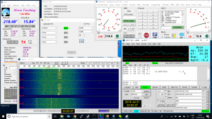
Most of the spare time during the weekend was taken up by relearning everything I had forgotten since I last tried EME and VHF data modes. I was able to confirm the setup was working correctly using GB3NGI beacon as well as some others on the make-more-miles on VHF site. Within around an hour I was successfully receiving SP4KM, ZS4TX and K5QE via the moon on 144 MHz.
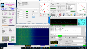
The screens above are rather busy with the rotator controller, NetworkTime program for keeping the PC clock synchronised via NTP, and CAT7200 which usefully translates the DTS/RTS line style PTT interface to a newer CAT/CI-V instruction.

As mentioned, when the moon was below the horizon, I also played around with other modes. SSB resulted in few contacts, but more than the ‘none’ I managed on CW. I quickly found my feet again on FT8, working into Germany, Denmark and the Netherlands. At the end of the weekend, PskReporter was showing the below map for M1GEO on VHF:

I have promised myself two things:

  1. To get on VHF more often. Well, do do more radio, basically!
  2. To finish the 144 MHz amplifier off. I have the basic functionality, but it’s lacking a user interface and other nice features. The hardware is there, but there’s no translation onto the nice graphics LCD.

Machining Heatsinks for QRO Amplifiers

Back at the 2012 Friedrichshafen Hamfest I brought a 1.25 kiloWatt VHF amplifier kit for 144 MHz from F1JRD and F5CYS. These devices were fairly new at the time. It took me a year to pluck up the courage to build the pallet, but I went about it all wrong. With the help of Dad and the kitchen hob, we soldered the jrd1 Teflon PCB to the C110 copper heat-spreader as suggested in the Dubus article (see here). I had the pallet working at the time, giving around 600W of RF, which was about the maximum my 1000W 50V PSU was capable of sustaining. When I came to boxing the device up into an amplifier to use with EME and Meteor Scatter in late 2016, the part failed under test.

After much deliberation, I have ordered parts to repair the amplifier project. I found Jim W6PQL‘s website (see here) a wealth of information, and Jim also offers to supply parts and designs to help others. I ordered a set of PCBs to replace the original jrd1 board, a NXP/Ampleon BLF188XR 1400W part to replace the failed the Freescale/NXP MRFE6VP61K25H 1250W part, and some other accessories that Jim sells. The parts were posted by Jim today, so I decided it was time to recover parts from the old PCB and recondition the heatsink and heat-spreader.

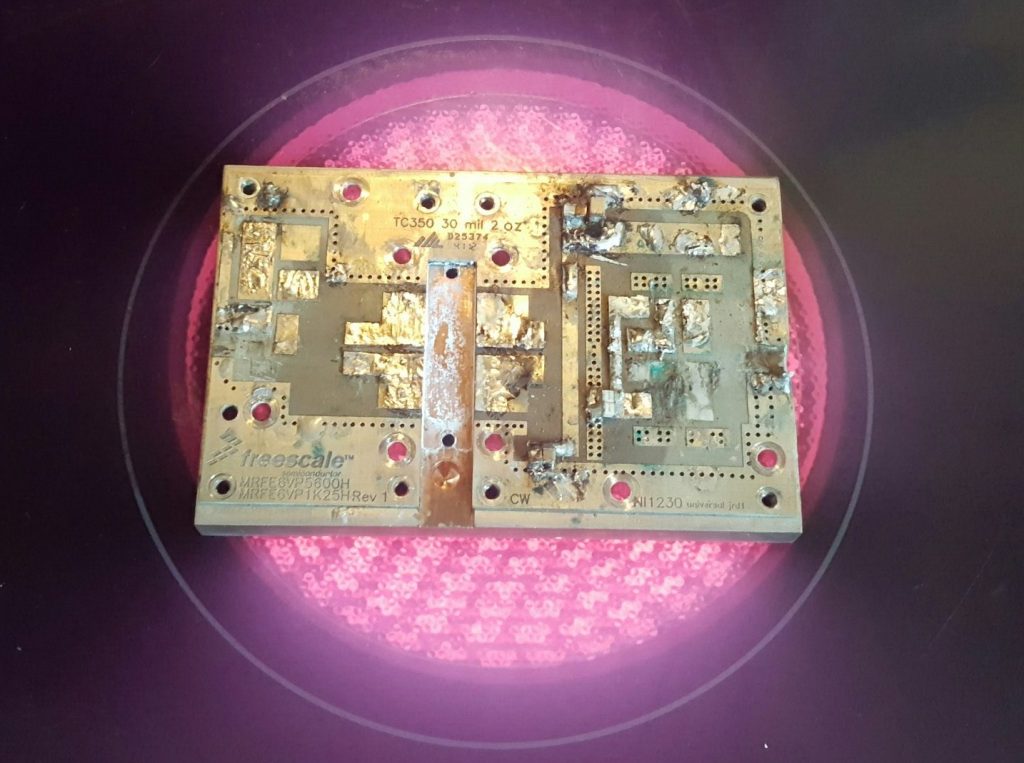
The first step was to remove the jrd1 board from the copper heat-spreader. I used the kitchen hob to heat the copper heat-spreader, since the old board was soldered to the copper block. The board damage was sustained to enable the removal of the more expensive components.

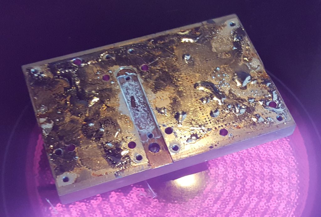
Below, the heat-spreader with the jrd1 board removed. I used a solder sucker and scraper to remove as much of the molten solder.

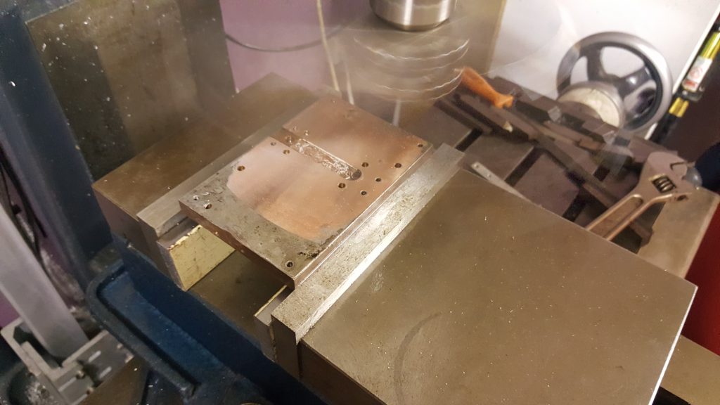
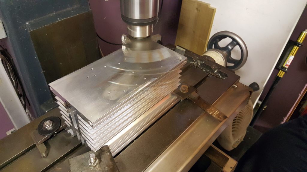
Once the heat-spreader had cooled down, I mounted the copper spreader up in the milling machine read to re-machine the top and bottom surfaces. Great care was taken to level the block using parallels. Below you can see the fly-cutting process on the first cut, removing just 0.05mm from the surface.

With the top and bottom of the head-spreader machined flat, a small end-mill cutter was used to machine the transistor slot to the correct depth following the skimming of the top surface. Then the heatsink mating surface was machined. Below you see the first cut on the heatsink.

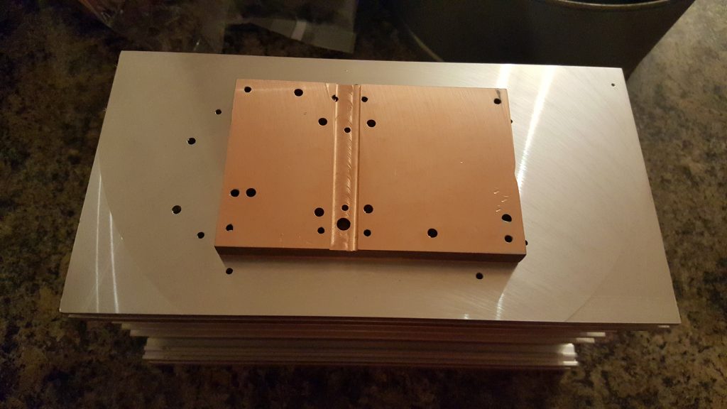
The finished parts. A few machining marks, but the surfaces are perfectly good enough. Some dents on the copper block, but it’s not worth removing all of the material to eliminate these.  Using a few drips of water as a substitute for thermal compound, the two mating surfaces stick together very well (with a good vacuum forming). That’s more than good enough for my needs!

Now I just need to wait for the parts to arrive before I can finalise the PCB and transistor mounting! This story continues here: Soldering Expensive Transistors.

144 MHz 1.25 kW Amplifier

Over the weekend I worked on my 1.25 kW solid state PA based on F1JRD’s design from Dubus using a MRFE6VP61K25H. I bought a complete kit at the Friedrichshafen Hamfest 2012 from F1JRD and F5CYS and built it up late 2013 but due to problems, I never had more than around 40W output. This weekend, with a new set of capacitors from ATC I rebuilt the output matching and fired it up once again. With my 1kW/50V power-supply I can get around 600W output, which his more than enough. This is still a work in progress, but things are moving forward with the project.