The topic of VHF and UHF propagation fascinates me, and with new tools and modes such as QRSS and WSPR I decided to have a play about. I tried on WSPR on 2 metres some time ago, with limited success due to drift on the band. I also wanted something I could leave at a nice high QTH and observe the results over a longer period. This is when I decided on the QRSS MEPT for 2 metres.
The rest of this page describes the “making” and “playing” with the parts and hopefully will document some results.
About the MEPT
The project begins with an ECray beacon purchased for £2 at a local rally. The board originally transmitted periodic data on 161 MHz, for an emergency beacon for reception via satellite.
![]()
The existing 13.4 MHz crystal was multiplied by 12 to give the desired frequency. Swapping this for a 12 MHz crystal as suggested by Dave Mills (G7UVW) on his QRSS 2m page yielded results in the low end of the 2 metre band. The issue being that it wasn’t possible to pull the 12 MHz crystal up enough in frequency to get the output near the QRSS/WSPR section, approximately 144.490 MHz.
Hunting through junk boxes I was able to find a 12.040 MHz crystal which when inserted into the 12x multiplier strip of the beacon gave a frequency of 144.480 MHz; much closer to the target. This requires pulling up 820 Hz, which was easily achieved with a small trimmer capacitor. A small crystal heater was added to help maintain the crystal at a constant temperature, and thus help maintain a stable output frequency when multiplied up to VHF. This proves to be very difficult, and a potential project would be to combine this with my homebrew GPS Frequency Standard project. I also removed the MCU end of the board to allow it to fit in a watertight enclosure.
![]()
Initial testing showed an output power of around 161 uW at the antenna socket. The original beacon I measured at around 200 mW.
![]()
Some modifications to the back of the PCB, adding extra capacitance into the tuned circuits to compensate for the lower frequency (144 from 161 MHz) helped immensely. In the end, the modifications were simple:
- 2.2 pF in parallel with C18
- 4.7 pF in parallel with C20
- 22 pF in parallel with C19 (this may not be optimal)
- 10 pF padding on crystal (adjust to get trimmer to required frequency range)
The image below shows the back of the PCB where these modifications where made:
![]()
After the modifications were made, I retuned the board to find the power had increased dramatically, to around 330 mW.
![]()
Initially, I had hoped to play with the PA on the board and get some more power, perhaps 500 mW. The maximum power I got out of the final stage was around 600 mW, but it died. I decided to be less of an idiot, and built a simple 1 W class-C amplifier from a 2N4427 with low pass filter. In its early stages, it looked something like this:
![]()
Obviously the first thing to note is that this amplifier, when turned up to eleven can do around 2 W, but learning from previous mistakes, I set the power to 1 W. Before going on air, I checked the output from DC to 1 GHz on the spectrum analyser to ensure it was reasonable. The MEPT meets the currently advised -60 dBc spectral purity, so we’re good to go on air.
All that remained was a little programming to send a CW ID and short explanation in CW at 20 WPM and the QRSS repeating every 10 minutes. This was done using an Arduino based on my Arduino QRSS project (see the Arduino menu entry in the Electronics group on the left). Timing is derived from the Arduino’s low grade computer crystal, so should be close enough short term, but may cause some issues in the long term. Hopefully the 10 minutes will be close enough to enable stacking. The CW message reads
M1GEO QRSS MEPT JO01CN 500MW PSE RPT VIA EMAIL
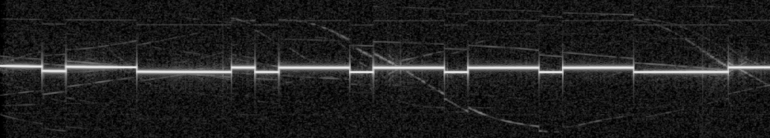
The QRSS then sends M1GEO with a 7 second dot speed to fill the remaining time approximately. An unmodulated carrier is then sent for the remaining time, waiting an internal timer for 10 minutes. The spectral domain looks as follows. Note the CW at 20 WPM is the left most part, which is unreadable due to the time-scale.
![]()
The whole project is mounted in a weatherproof box, feeding just 13.8 V DC in and RF out.
![]()
Reports
Dave G7UVW
Two reports from Dave, G7UVW at a distance of 3km? His S-meter reading was 59+10dB!
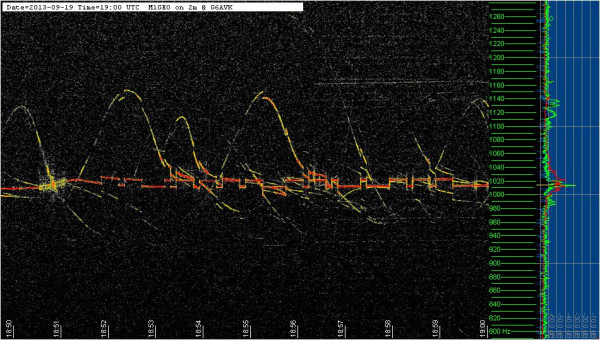
Colin G6AVK
A very interesting report via Twitter (here & here) from Colin, G6AVK, over about 31 km. His S-meter reading between S3 and S5:
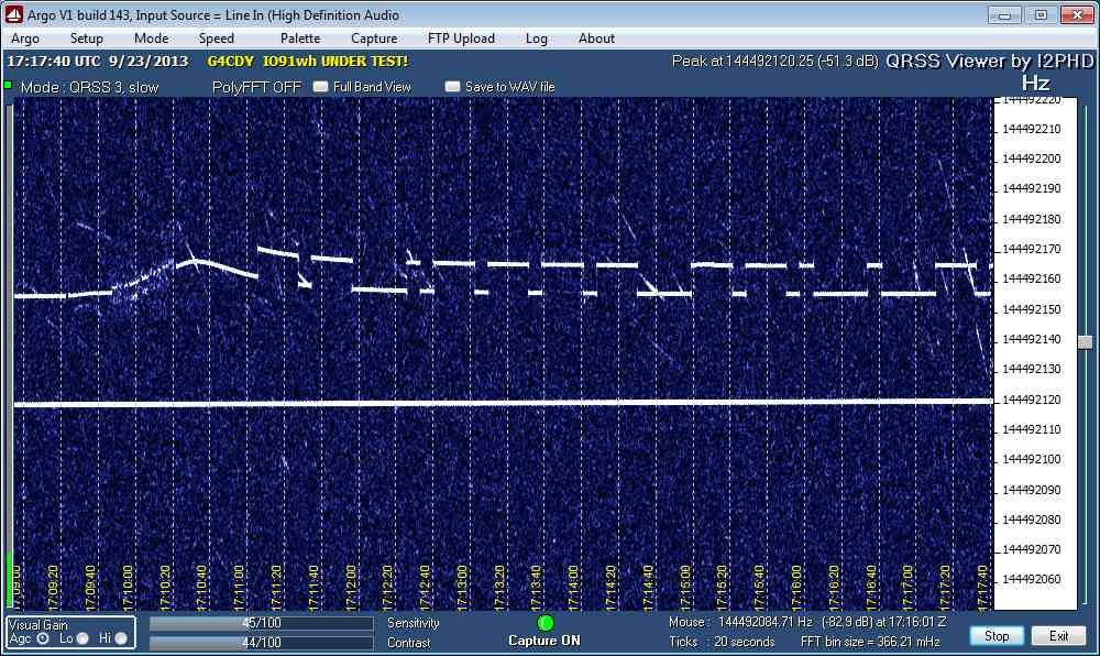
Terry G4CDY
From Terry, G4CDY, about 36 km. A nice strong signal.