
During the December 2015 meeting of the Camb-Hams, Gavin M1BXF had brought along his small, home-brew amateur radio project – The mcHF transceiver – which he had been building for a week or so prior to the gathering.
Having seen the mcHF function on a small antenna, members were interested, and a group buy was set-up, headed primarily by Geoff G0DDX guided by Gavin M1BXF.
This page documents my progress with the construction of the project.
The bits arrived in at the January 2016 meeting of Camb-Hams, in a nice plastic box from Geoff G0DDX. The following Saturday, with a few spare hours, I decided to make a start.
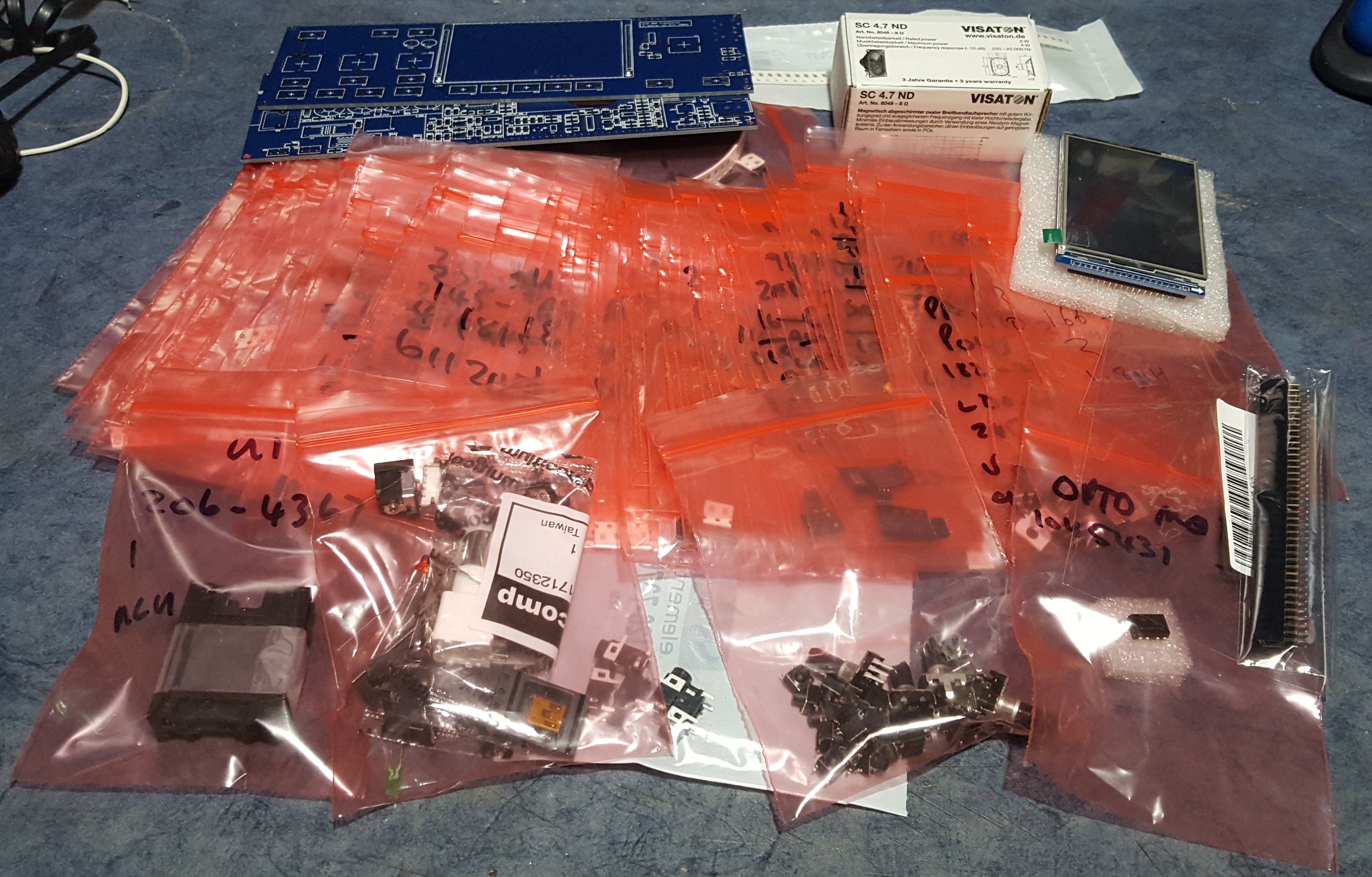
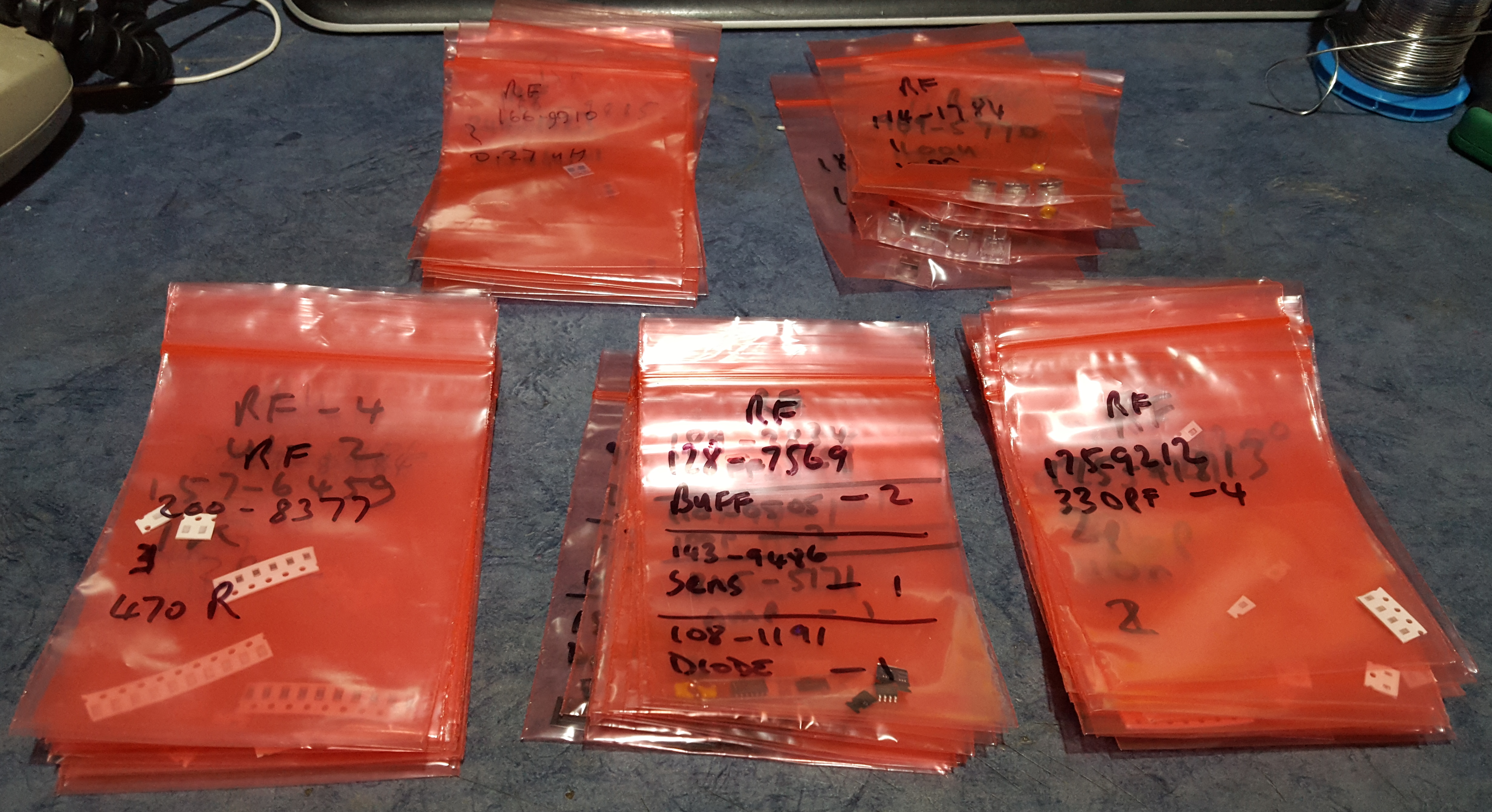
There were lots of bits, so in order to make finding parts easier, I decided to sort them into some loose groups. All resistors went together in a pile; all SMT capacitors together, and all larger capacitors together; inductors formed another pile; finally all the semiconductors went together.
The first step was to build the power supply section. This is a straightforward build, but was a bit fiddly due to the requirement of the voltage regulator bodies to be flush to the PCB – the 7805 regulator had stepped legs, which needed trimming before the part would sit flush on the board.
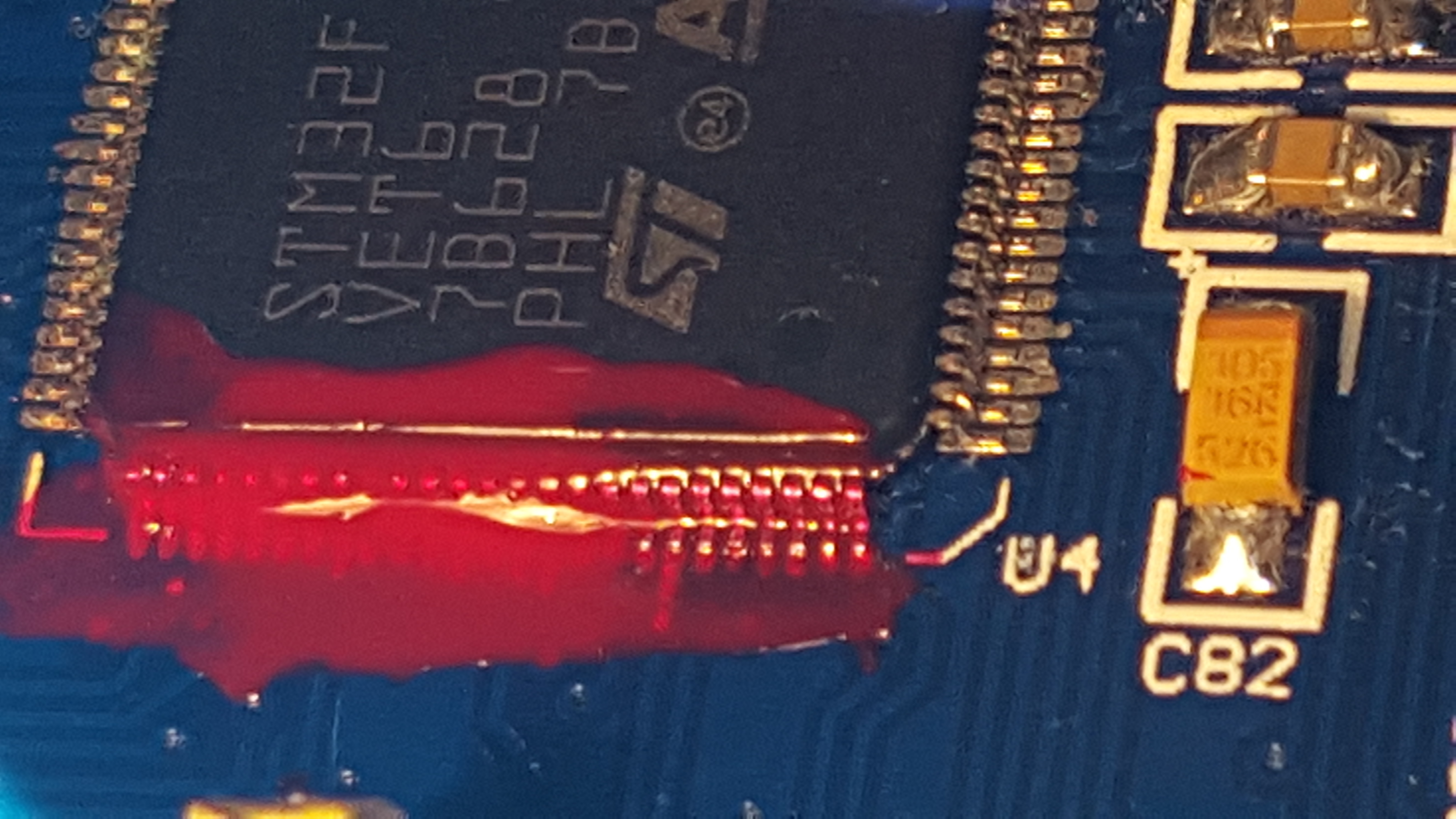
The first major hurdle was to mount the main MCU chip – the STM32W. This took some time to align correctly, and a brave and steady hand. I had intended to use the drag method to solder the part down, but that didn’t quite go to plan. I ended up smothering the chip pins, then using a solder sucker to remove the bulk of the residual solder, and solder wick to clean the rest!
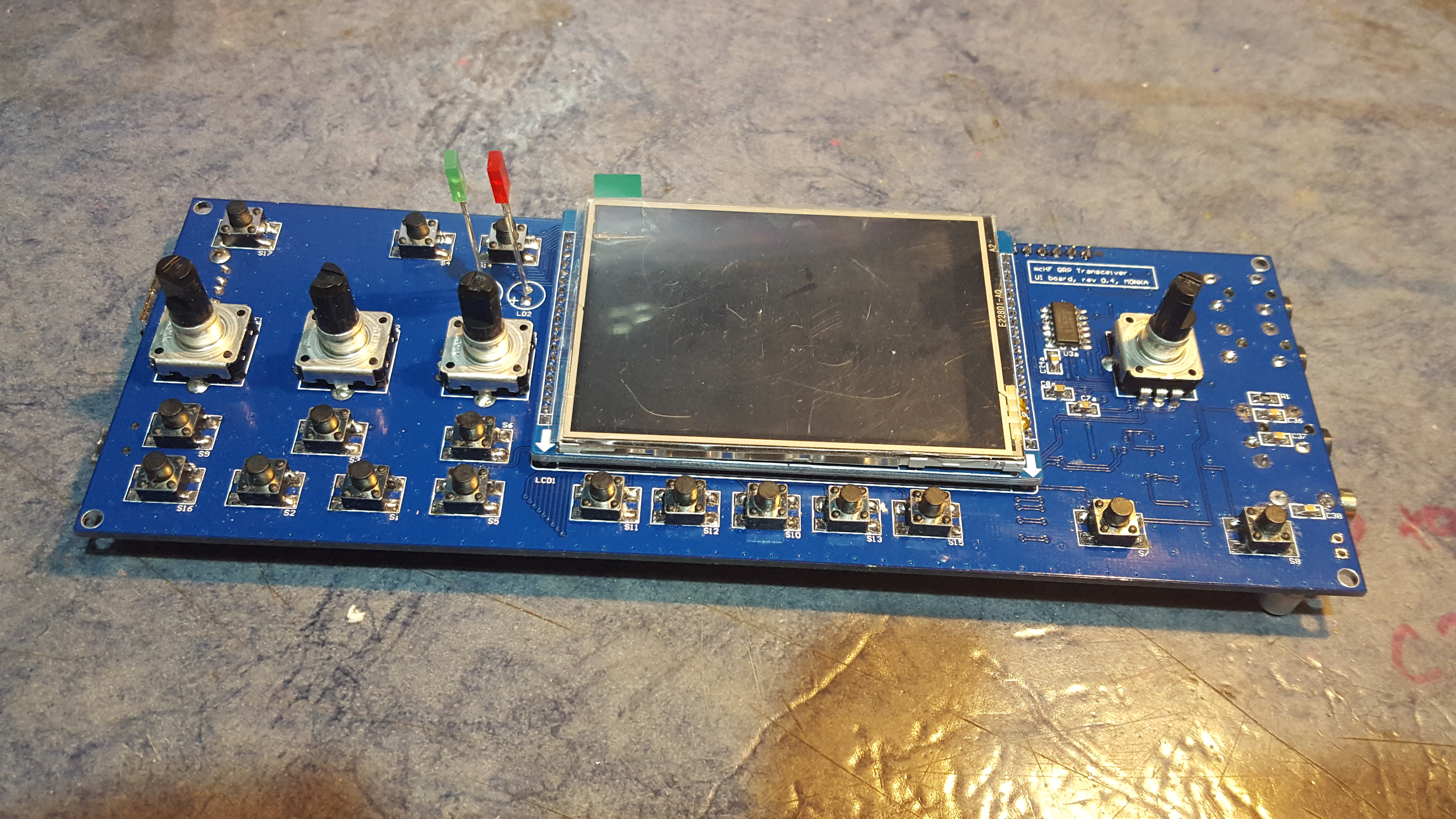
After a second stint of around 6 hours, I finished the UI board. I had soldered everything but the LCD, since fellow Camb-Ham Bob G3PJT suggested the displays weren’t correctly initialising. The LCD is a tight fight in the PCB, so I decided to push-fit it, and see how I got on.
After some cleaning with flux remover and washing the board, I decided to power it. To my surprise, the display backlight burst into glory. I noticed the input current gradually creeping up, stabilising around 400 mA, which seemed quite high. Gavin M1BXF reported an expected current of 200 mA, which is about where mine starts from.
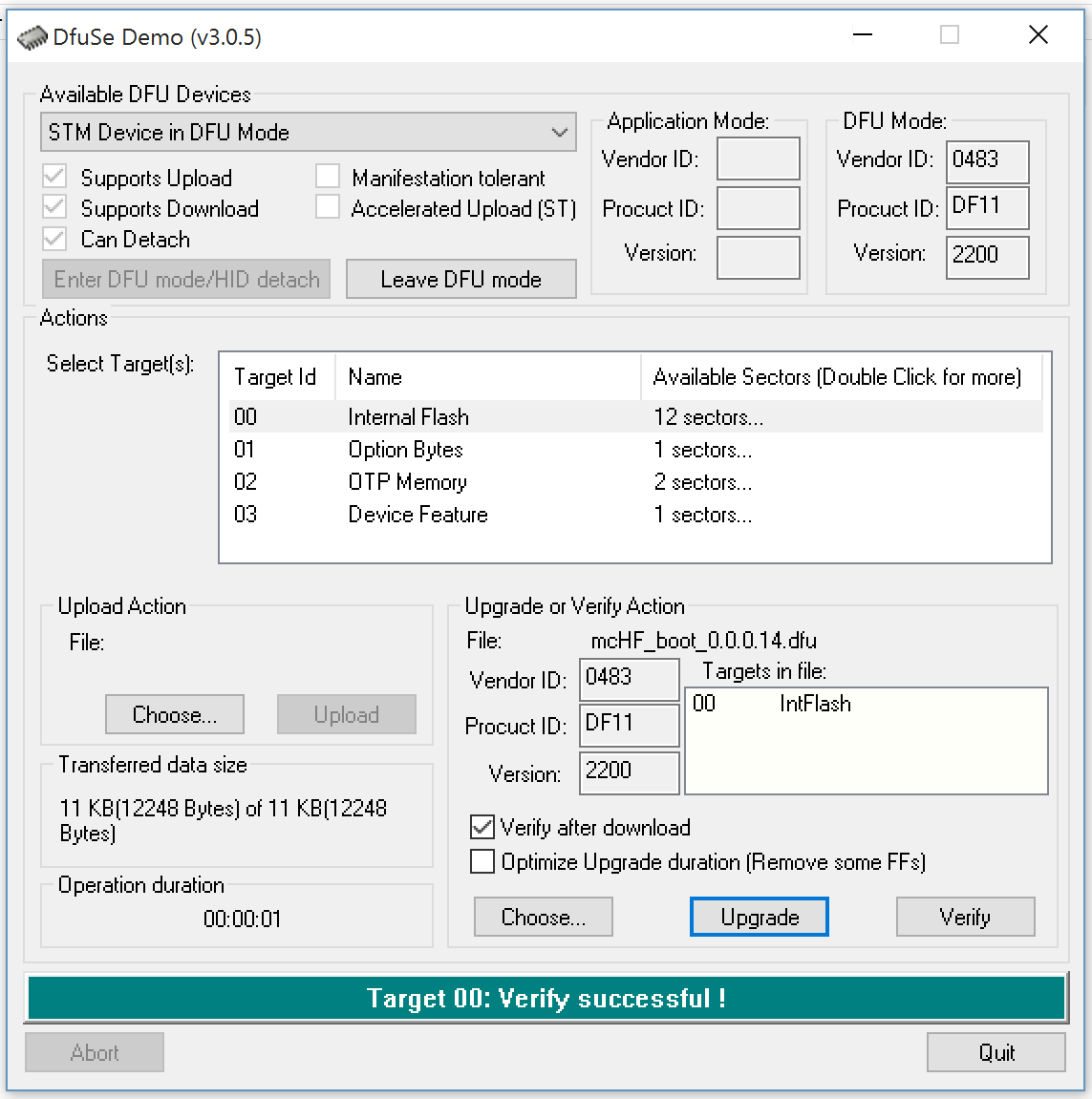
In a generic (but insane) test, I held the power on for a while (there is no latching at this stage, as the MCU isn’t programmed to hold it’s own power on) and see what got hot, but nothing did. I decided to chance my luck and plug it in to the computer, following Chris M0KNA instructions on programming the bootloader. The mcHF (or at least the STM32 is visible to the computer for a short while, maybe around 10 seconds, before the device disappears. In this time, I was able to confirm that the ST bootloader loader DeFuSe was able to see the radio.
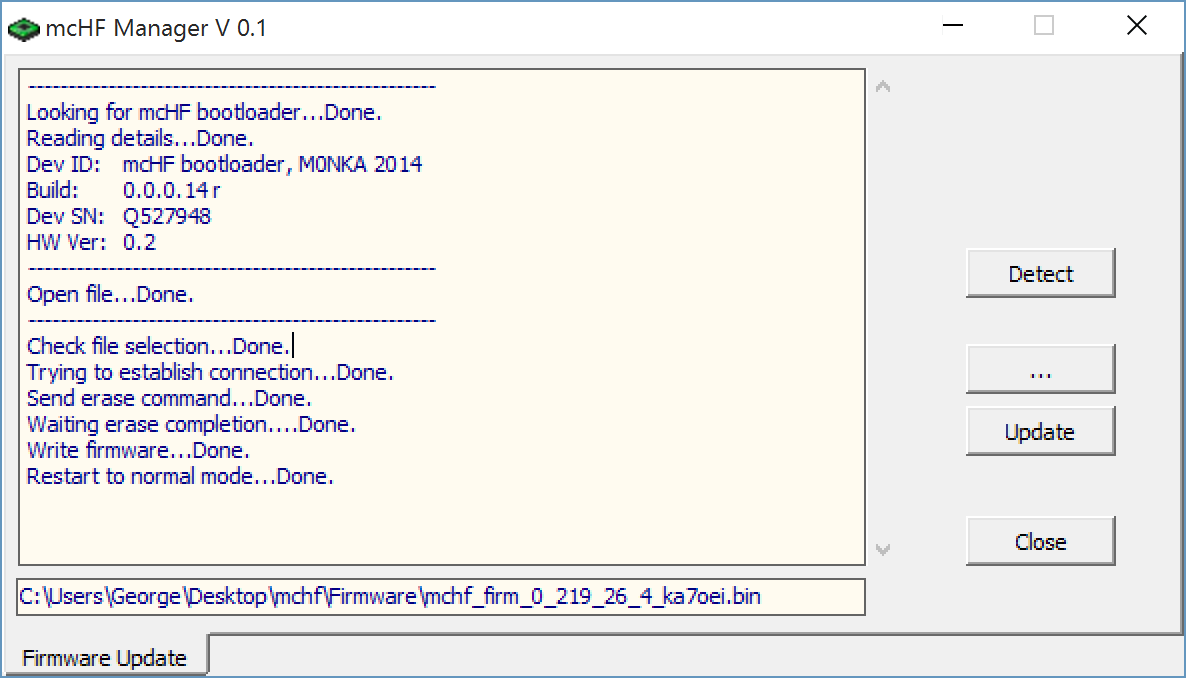
This was diagnosed to be an incorrectly orientated capacitor C97. Rotating this resolved the problem, and I was able to install the boot-loader and flash the firmware as expected.
After playing around a little with the previously built UI board, I noticed that my mcHF hung (for about 1/2 second) when I rotated the frequency dial. It was a noticeable glitch. At the time, I assumed it was because the MCU was trying to talk with the Si570 or something, and as I hadn’t build that part yet, it was having trouble.
Now that I have now built the LO section, it’s still doing the same. A quick conversation with Chris M0NKA revealed that if the frequency is in red (which mine was), there is an error on the I2C bus interfacing to the LO – essentially, it’s shorted somehow – and there’s no communication on the bus.
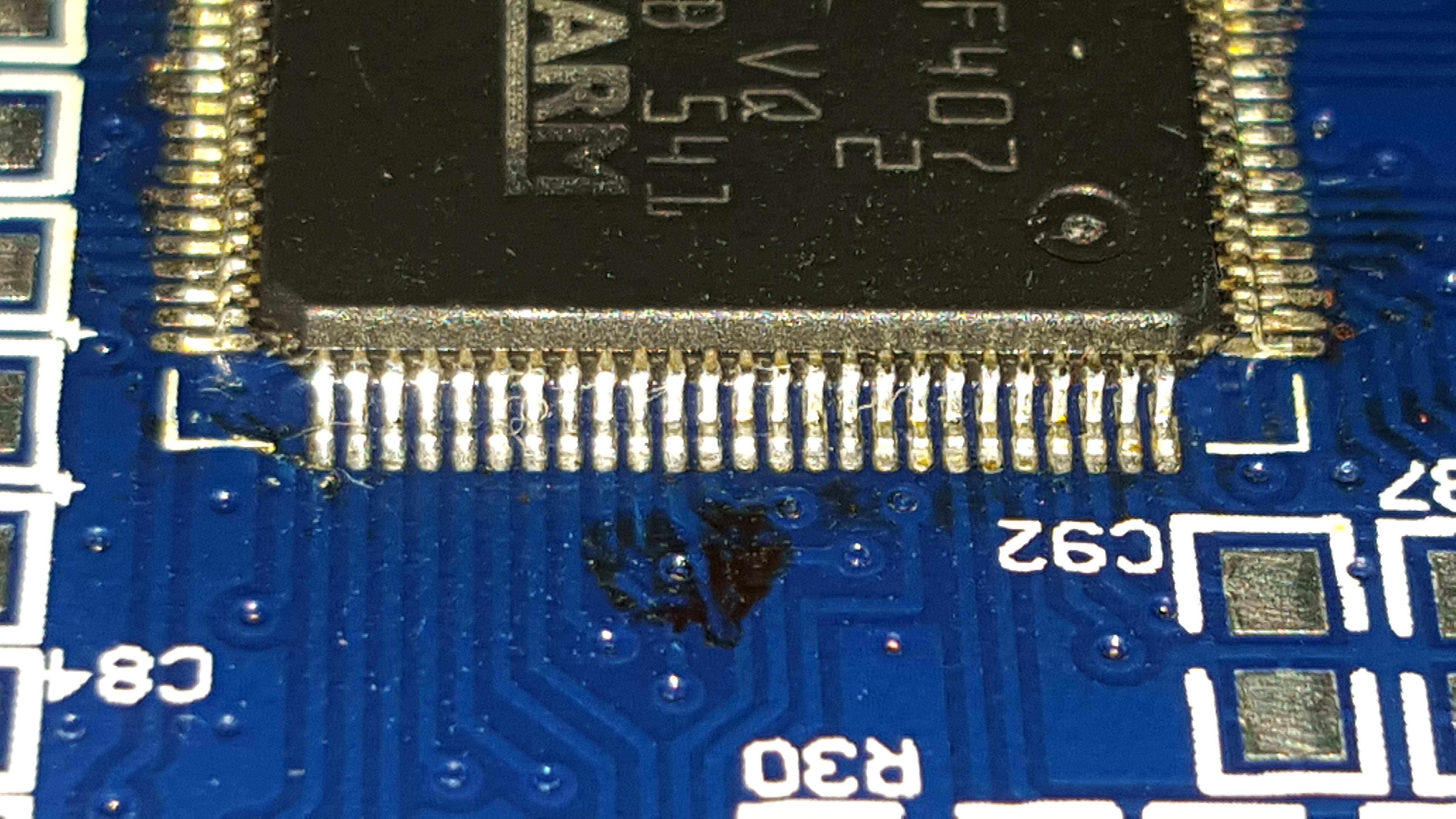
This turned out to be a short under the STM32 chip – solder had tracked under the IC (probably as I applied far too much initially – be warned!). The only way to fix this was criminal! I decided to lift the offending track, realign the MCU pin, slide the cleaned track back under the MCU pin and resolder. After about 2 hours of surgery, I had cleared the fault with the SCL line being bridged to the neighbouring pin.
The only downside is that the back of the UI Board looks a total mess. At one point I was about to throw it away, and start again on a new UI Board. Or at least a new STM32; but it did survive. I added some nail varnish to hold the lifted track securely – this makes the back of the UI board look very poor, but I believe it is of mechanical advantage… Moral of the story; don’t use too much solder (or do it properly in a SMT oven!).
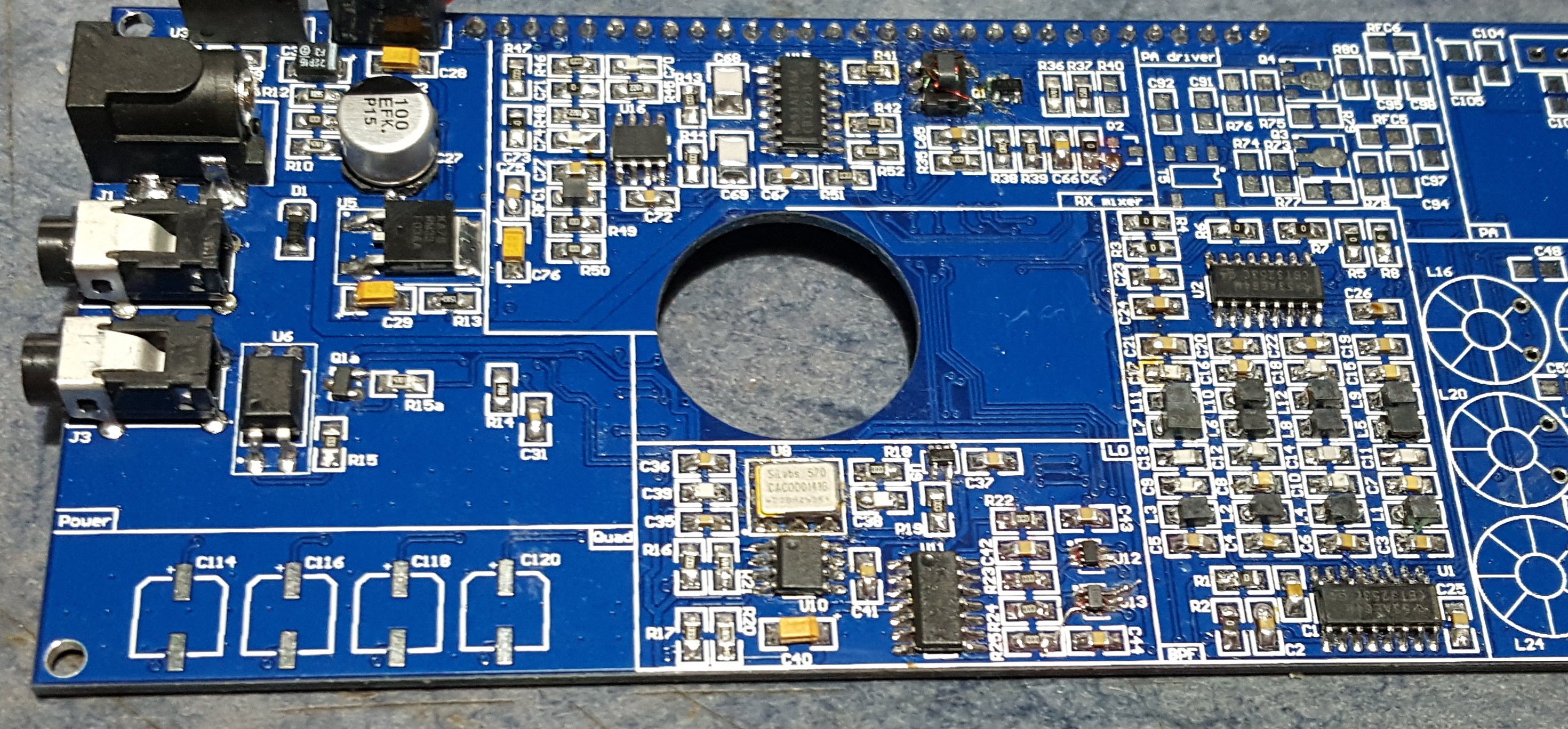
After another stint, I was able to solder the bandpass filters and the remainder of the receiver circuit.
I removed the red nail varnish I had before, and tidied up some of the tracks. I applied a much smaller amount of clear nail varnish where required, but in fact, this turned out to be minimal. Feeling slightly more patient than previously, I slowly and methodically re-worked all of the pins from U4. This not only fixed a bug where the radio occasionally restarted, but several other poor joints were also improved.
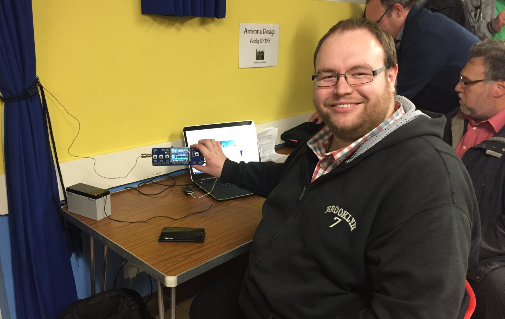
Monday 18th January 2016 saw the EssexHam January Meeting, where I took along the mcHF to the show-and-tell style meeting.
During the meeting, I also managed to ponce a few metres of thin wire from Graham G7JYD to wind the filters and transformers in the transmitter. Now I have no excuses for not getting the transmitter done!
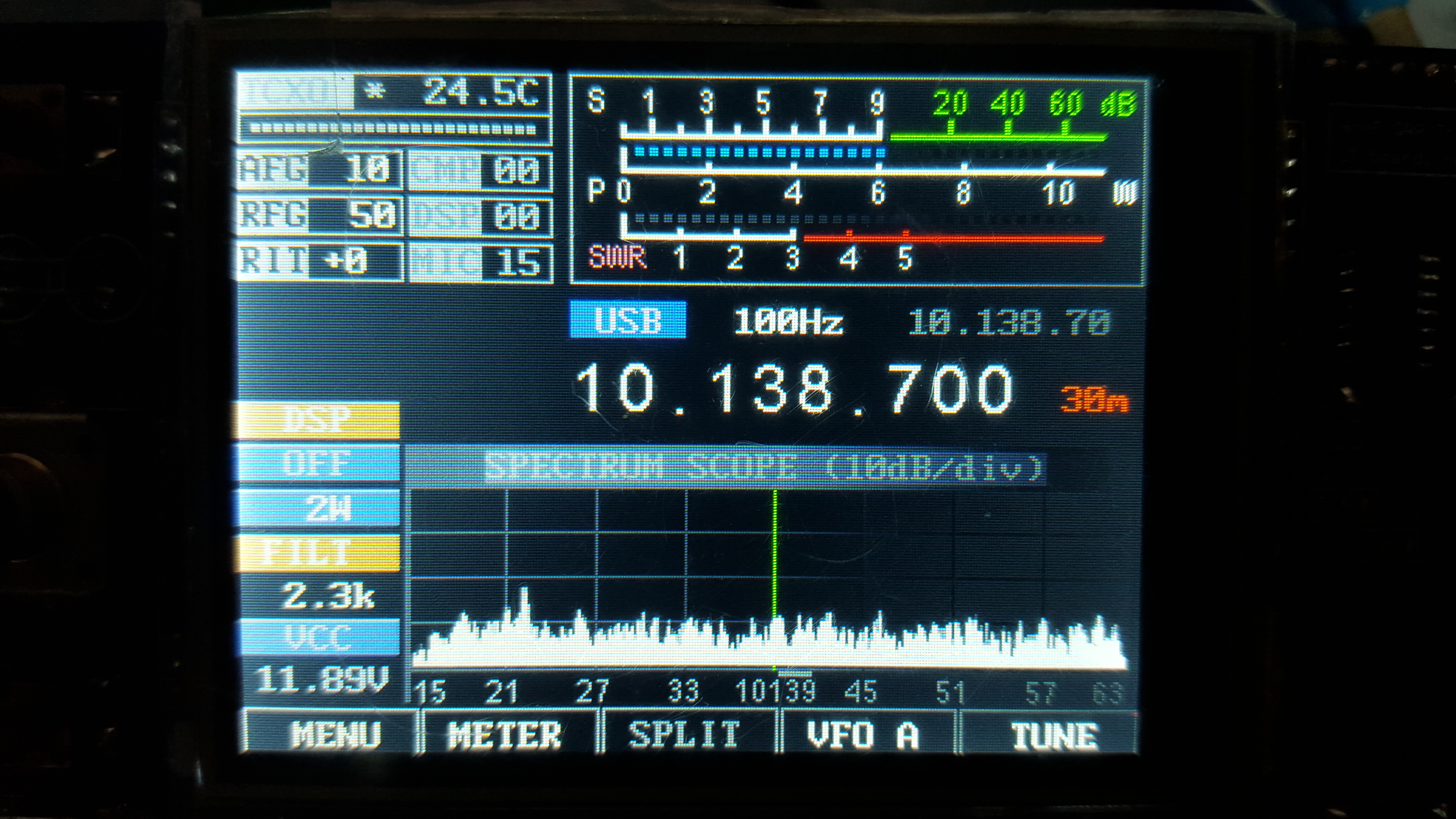
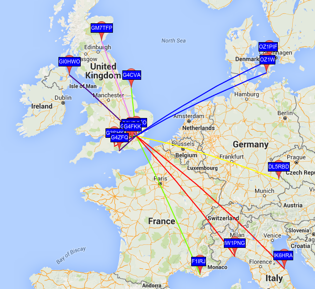
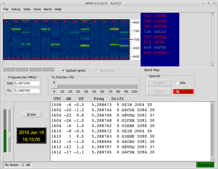
After returning from EssexHam, I fired up WSPR and left the mcHF purring away. The antenna was only a short length of wire around the inside ceiling of the shack, so signals were poor – I followed the bands downwards throughout the evening, ending on 5 MHz (60 metres).
The map for my short piece of wire was as follows:
And the waterfall of the WSPR Screen:
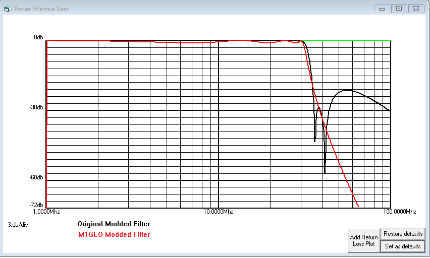
After a break of about 5 months, I finally got around to finishing the mcHF off! I’m pleased to say it’s working, and I have made several contacts. The 17-10 meter filter wasn’t looking so happy, so I have redesigned that:
Here, I am monitoring the 20m JT65 frequency using the USB audio cable.
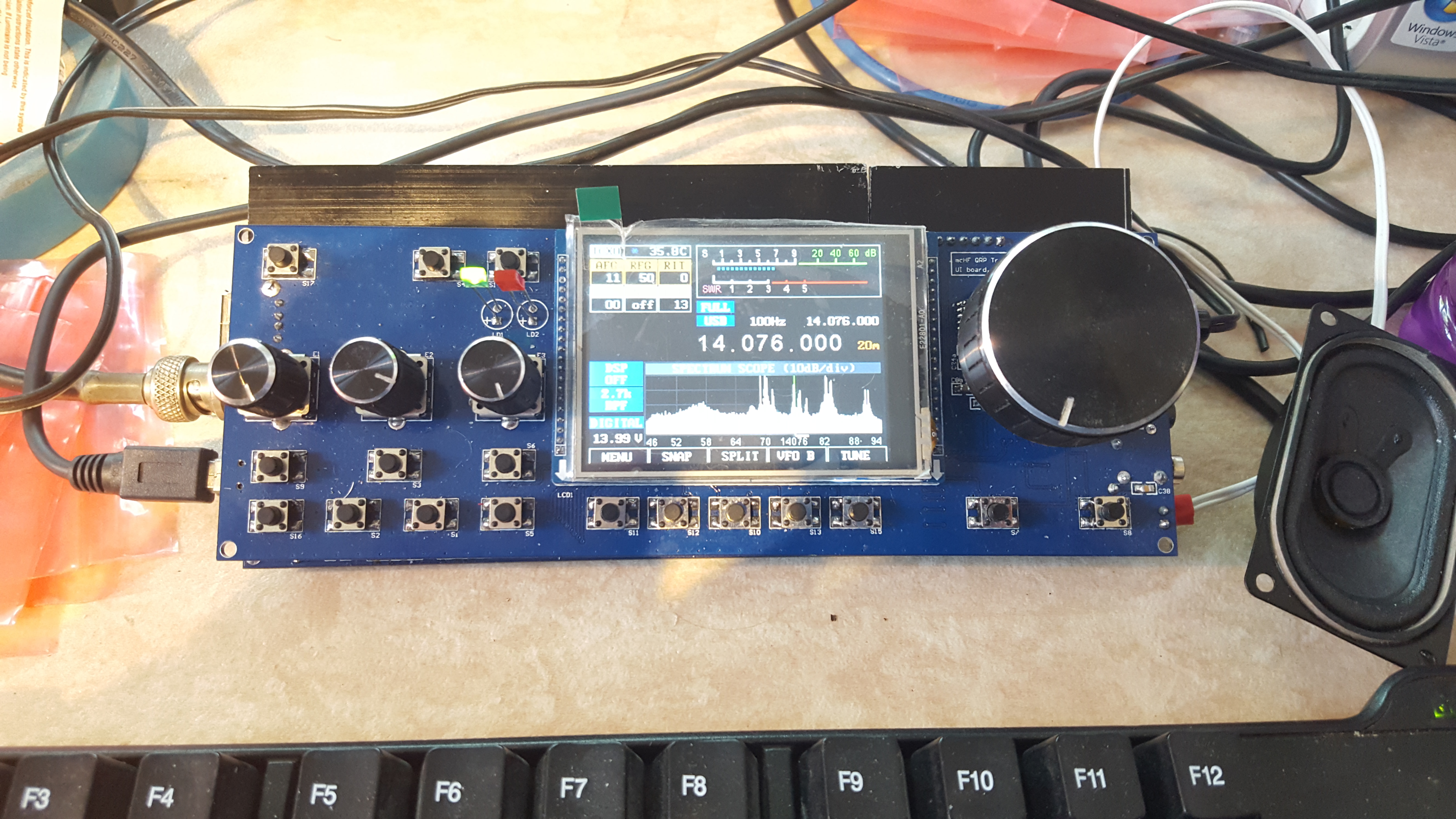
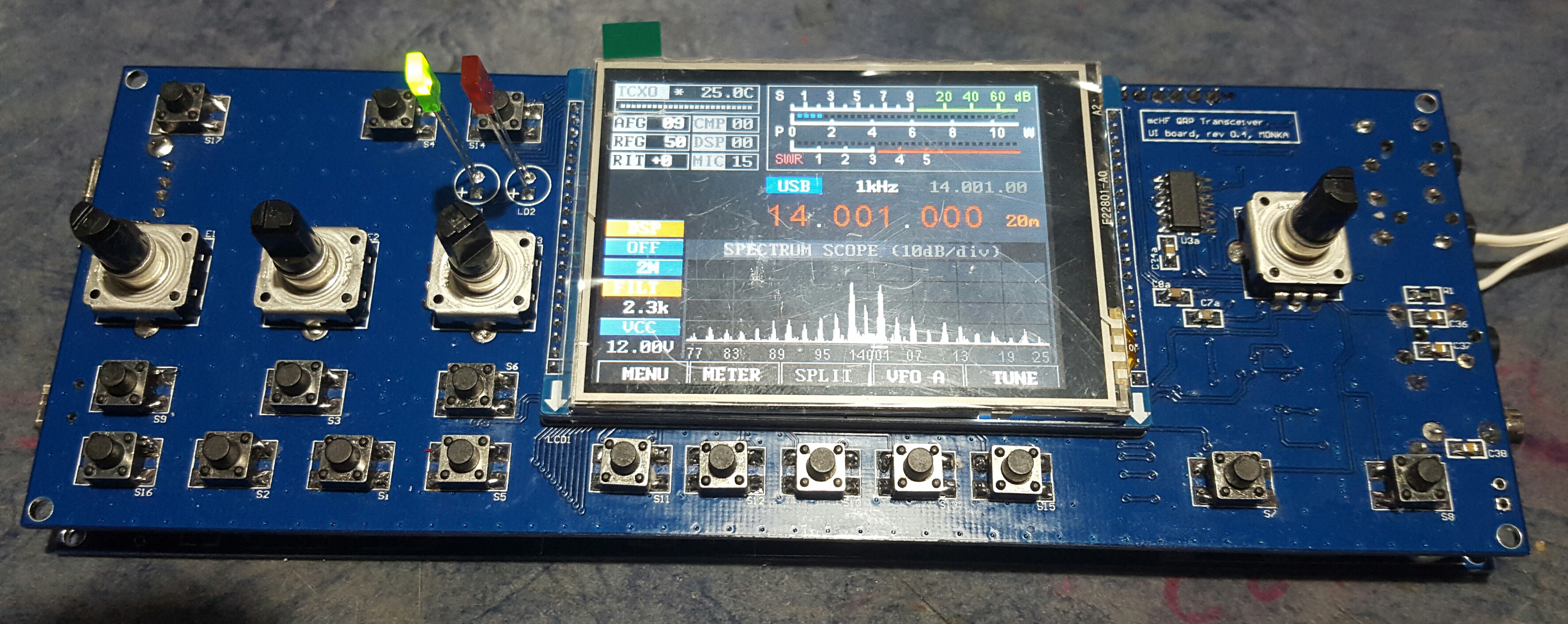
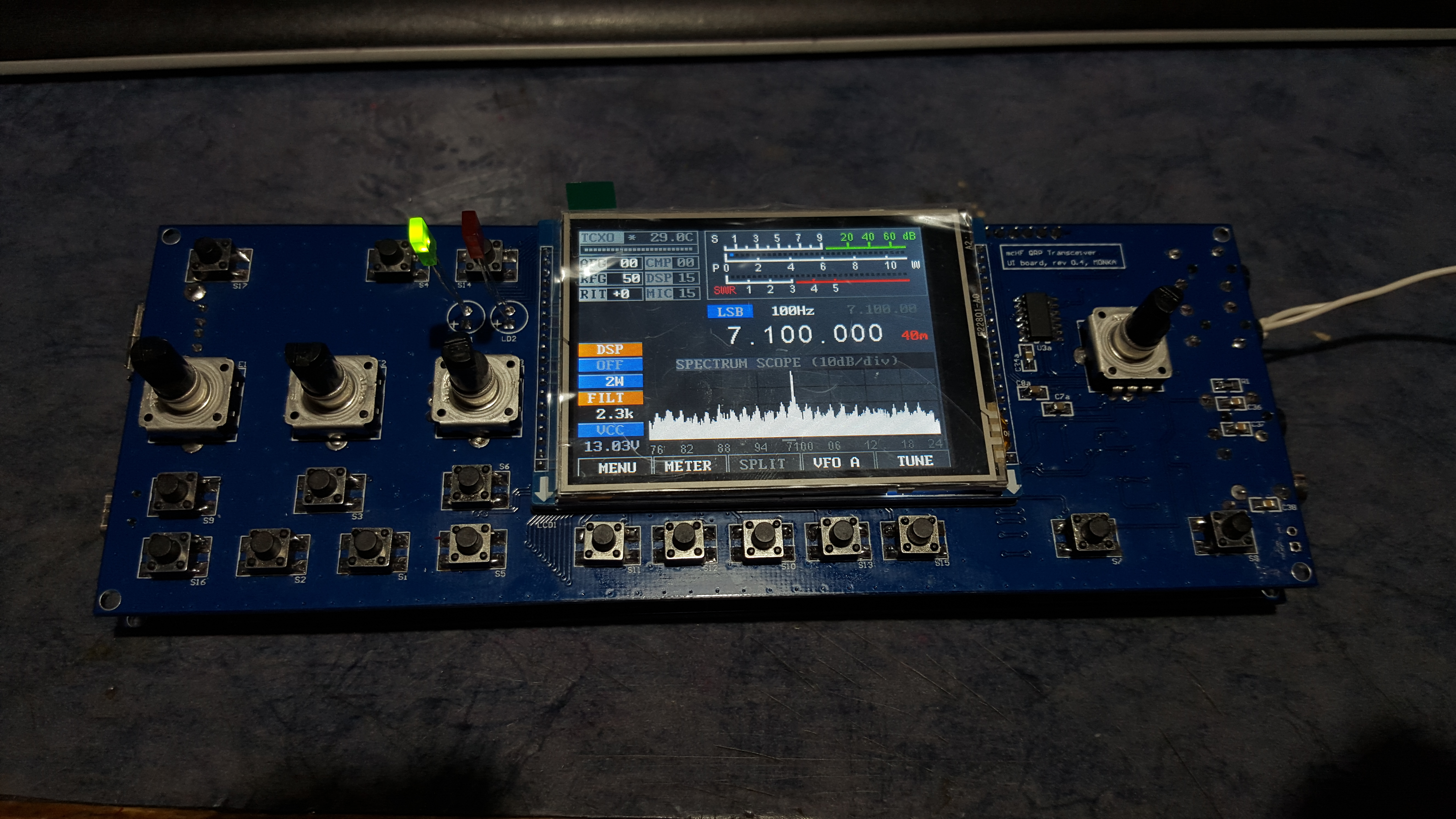
Some views of the radio construction.
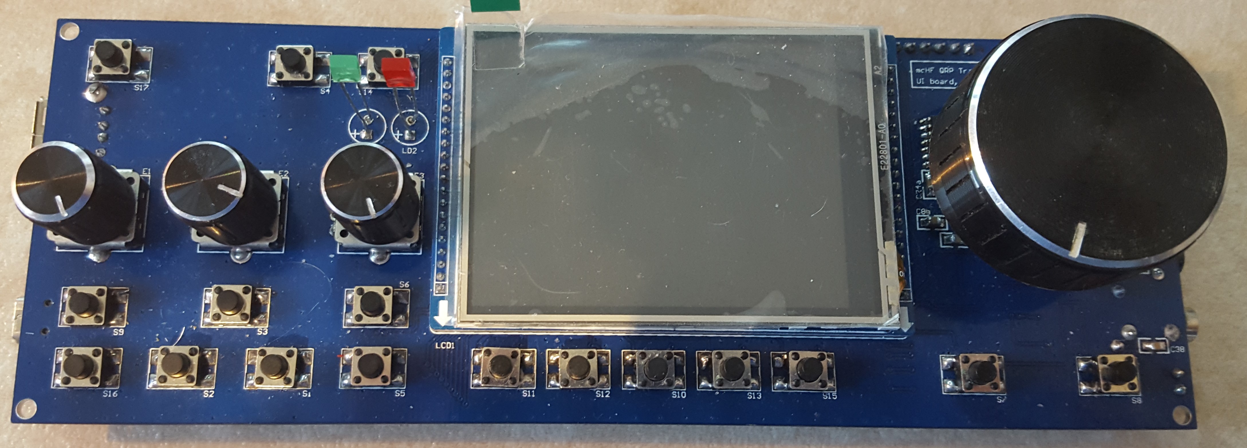
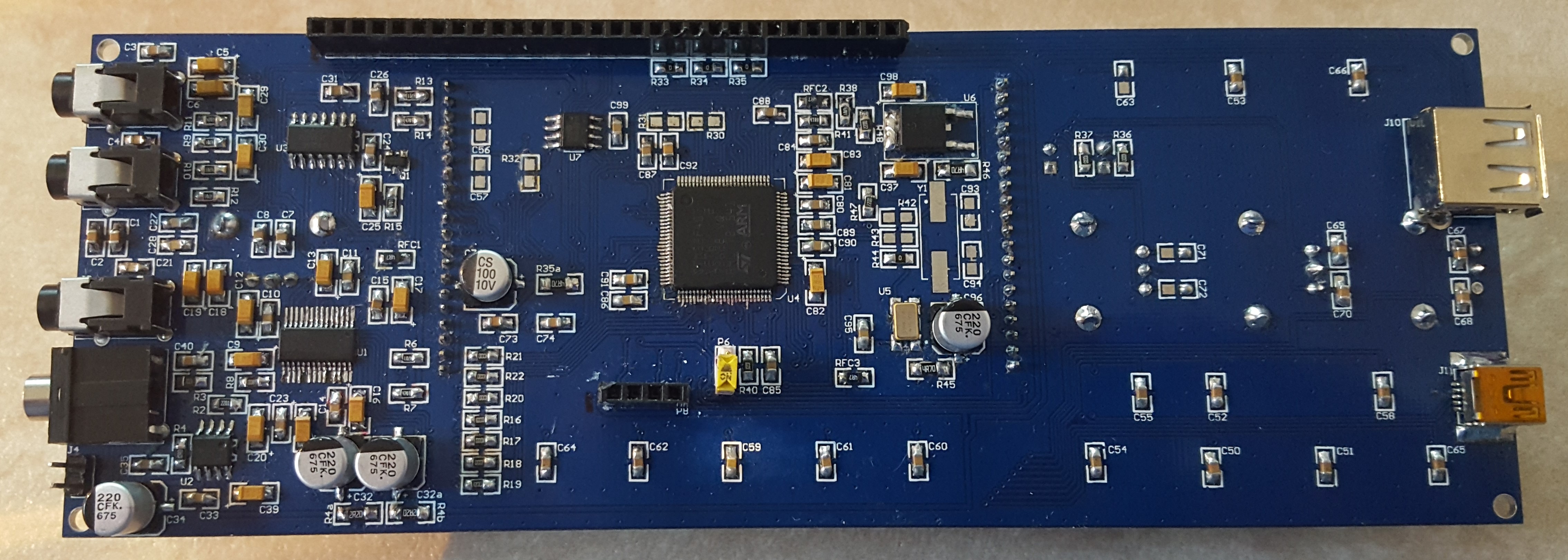
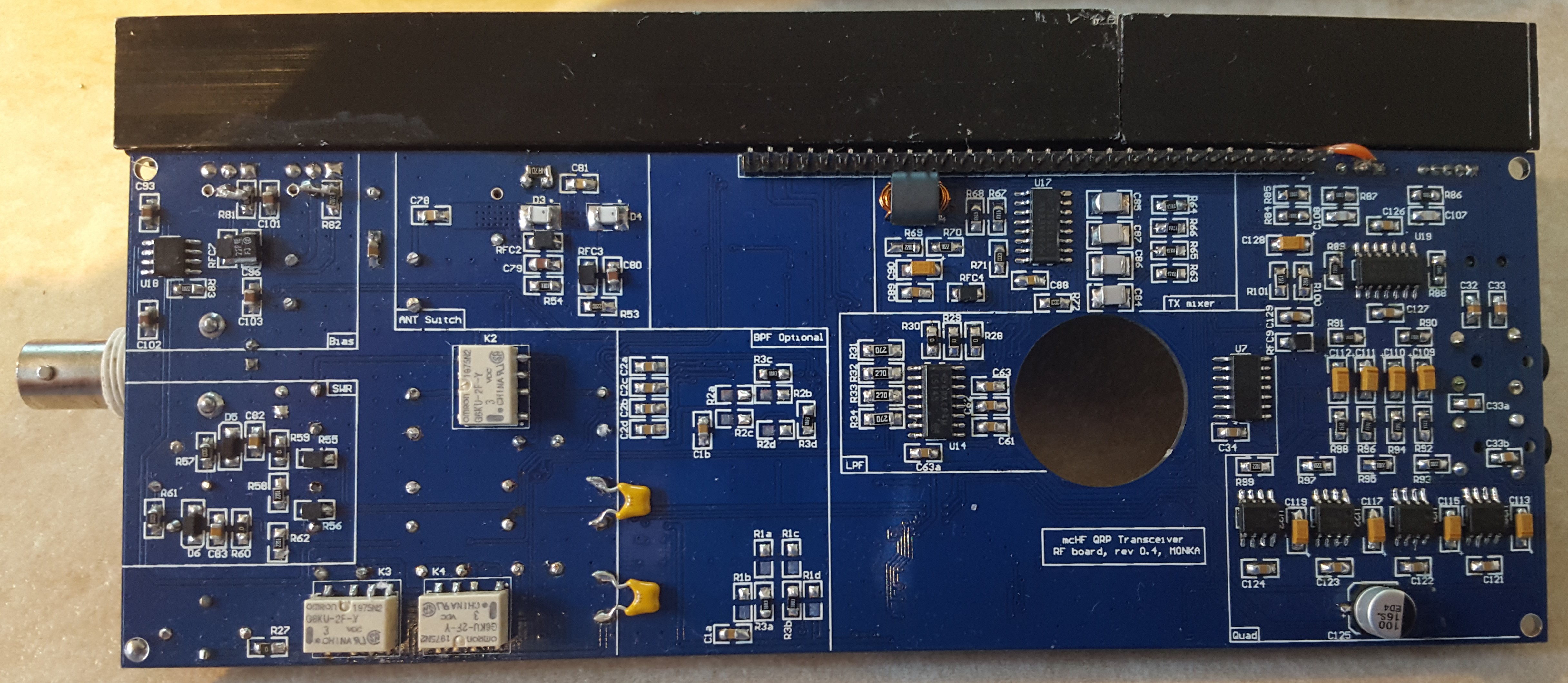
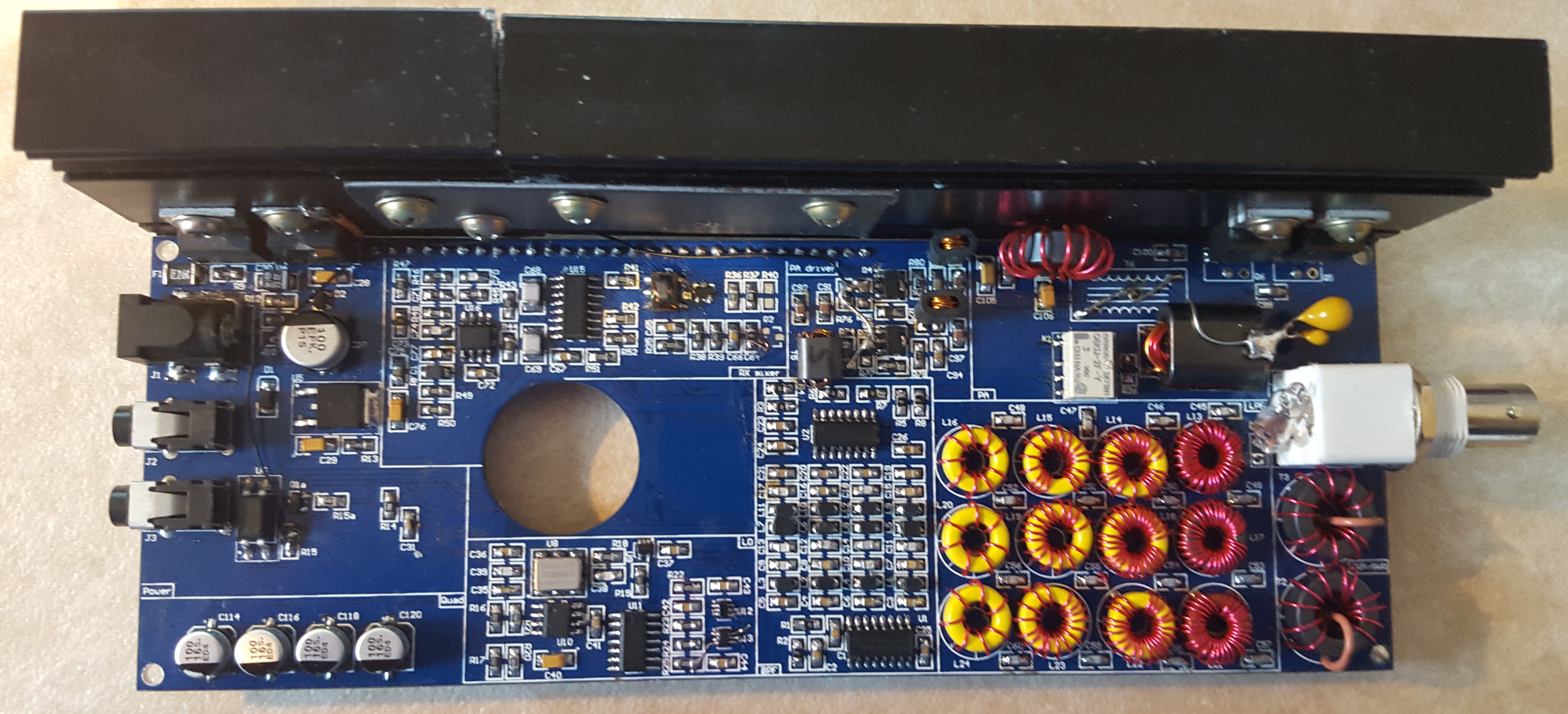
All hand soldered, including the big ARM core, using a soldering iron 🙂