
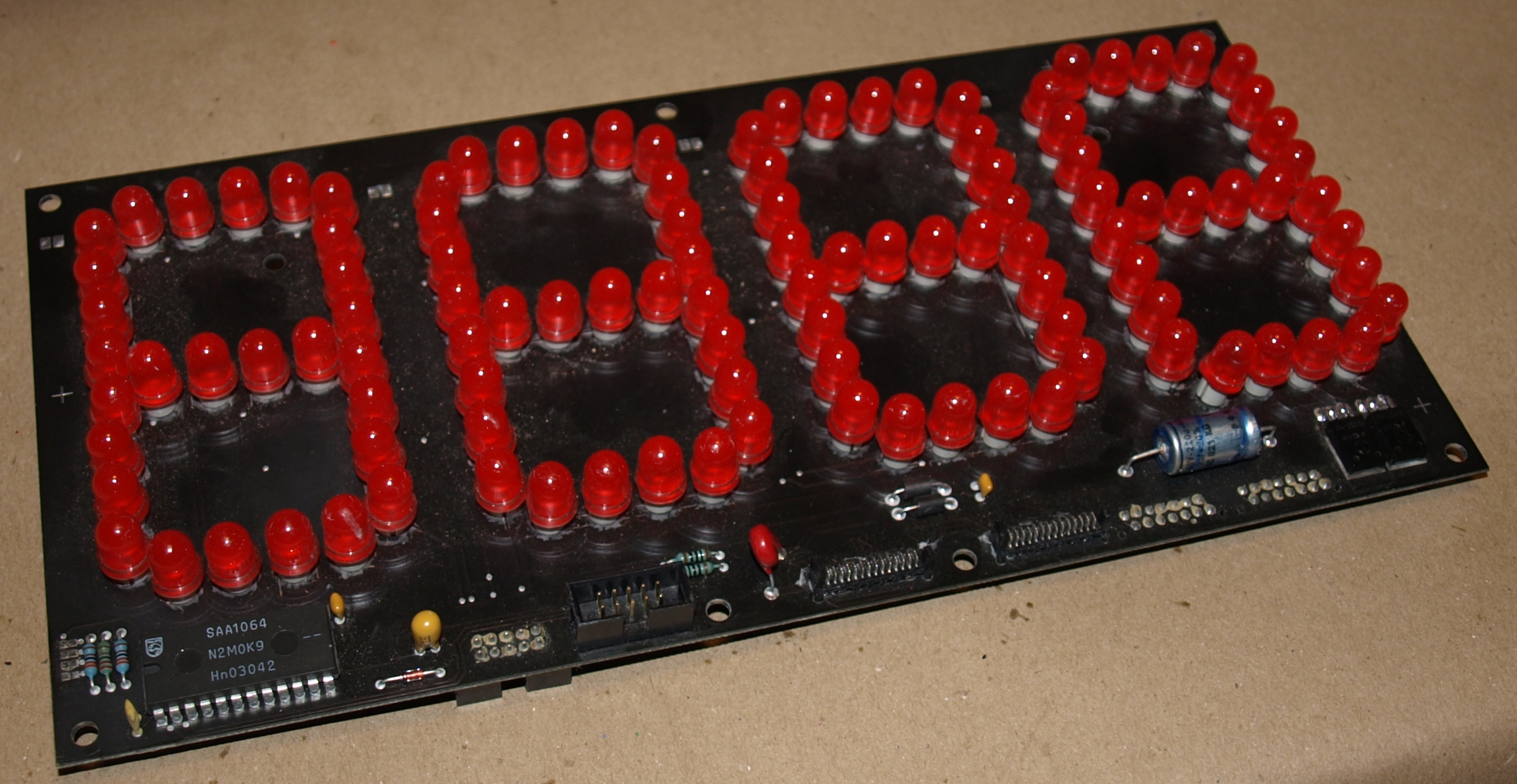
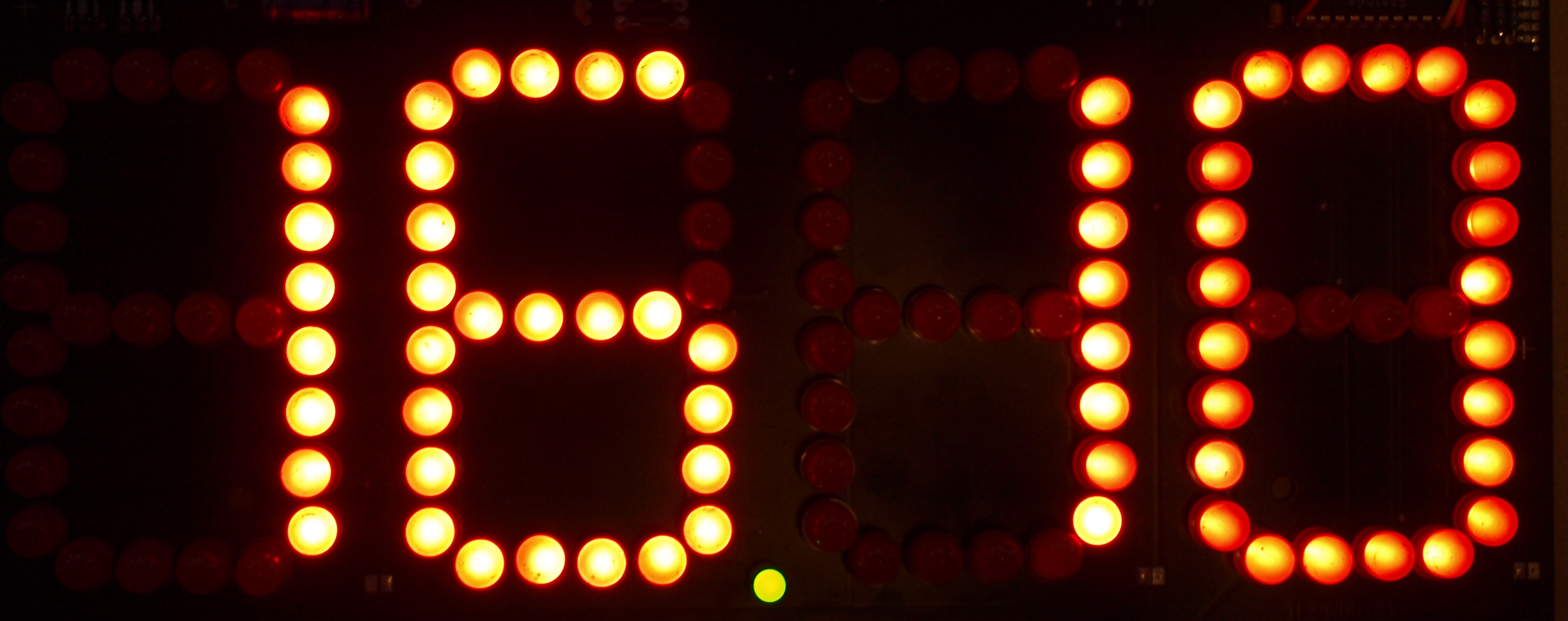
At a Ham Radio rally some time ago, I bought some of these huge 7-segment-display modules. They have character height of roughly 8 centimetres with four digits. Anyone who knows me will know I am fascinated with time and especially clocks of any variety. These were a must have for me, and I got them at a cheap price. I have no idea of their intended purpose. Best I could think of was for the prices of fuel at petrol stations – you know – on the big road-side signs. Anywho, it doesn’t matter. Here’s one of them:
Connections
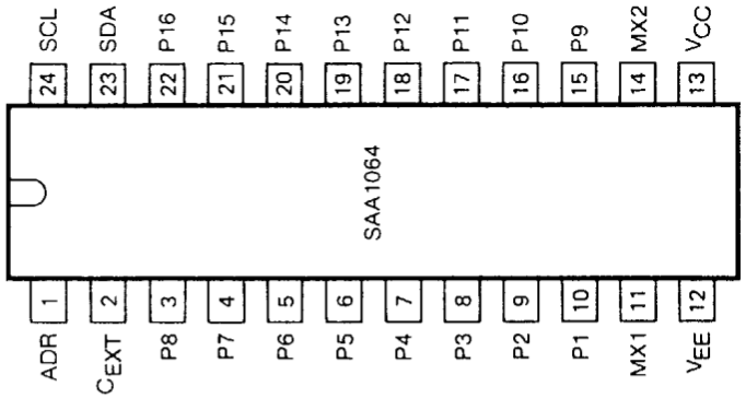
I am concerned with the data pins, SDA (Serial Data Line) and SCL (Serial Clock Line) [24. These are the  bus connections. It is important to note that the bus is an open collector bus, and so pullup resistors are required.
As I am an animal, I decided that the best course of action would be to solder directly to the SAA1064 IC. The tracks on the PCB were very thin and the board already had a few dry joints and broken components where it had been transported to and from the rallies.
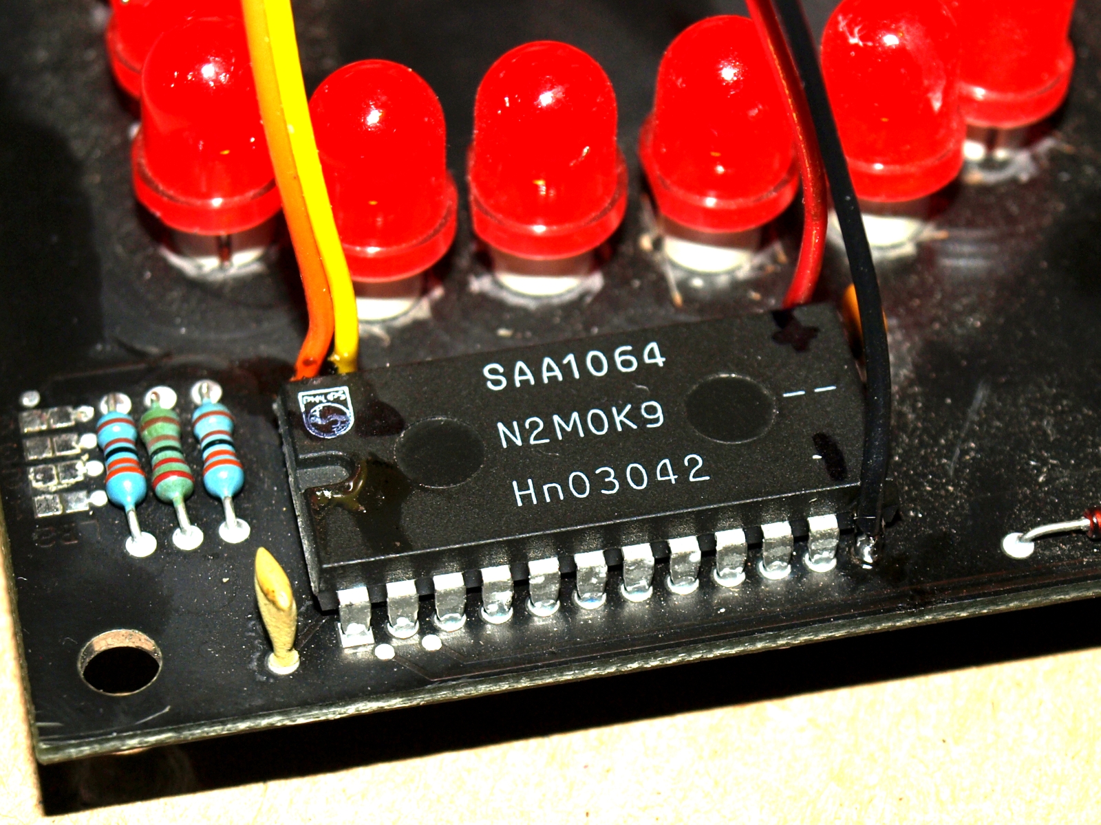
bus pull-up voltage. The two resistors (visible below) as as the bus pull-ups. The bus is an open-collector bus, which allows for sophisticated protocol features such as bit-stretching (none of which are implemented in my code – see further down). The clamp line prevents over-voltages from damaging the Velleman K8055 board.
Segment Mapping
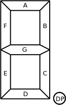
The digit byte sent to the SAA1064 represents the 7 segments of the display. The 8th bit is the decimal point. I added a green LED to my board, as the decimal point. It breaks up the display very slightly. I had to map the 7 segments out to make numbers. These can be found in the code for this project inside the variable “character_map[]”. Here is how I worked it out.
| Digit | Segment | |||||||
| # | A | B | C | D | E | F | G | D.P. |
| 0 | 1 | 1 | 1 | 1 | 1 | 1 | 0 | 0 |
| 1 | 0 | 1 | 1 | 0 | 0 | 0 | 0 | 0 |
| 2 | 1 | 1 | 0 | 1 | 1 | 0 | 1 | 0 |
| 3 | 1 | 1 | 1 | 1 | 0 | 0 | 1 | 0 |
| 4 | 0 | 1 | 1 | 0 | 0 | 1 | 1 | 0 |
| 5 | 1 | 0 | 1 | 1 | 0 | 1 | 1 | 0 |
| 6 | 1 | 0 | 1 | 1 | 1 | 1 | 1 | 0 |
| 7 | 1 | 1 | 1 | 0 | 0 | 0 | 0 | 0 |
| 8 | 1 | 1 | 1 | 1 | 1 | 1 | 1 | 0 |
| 9 | 1 | 1 | 1 | 0 | 0 | 1 | 1 | 0 |
| A | 1 | 1 | 1 | 0 | 1 | 1 | 0 | 0 |
| B | 0 | 0 | 1 | 1 | 1 | 1 | 1 | 0 |
| C | 1 | 0 | 0 | 1 | 1 | 1 | 0 | 0 |
| D | 0 | 1 | 1 | 1 | 1 | 0 | 1 | 0 |
| E | 1 | 0 | 0 | 1 | 1 | 1 | 1 | 0 |
| F | 1 | 0 | 0 | 0 | 1 | 1 | 1 | 0 |
| . | 0 | 0 | 0 | 0 | 0 | 0 | 0 | 1 |
| 0 | 0 | 0 | 0 | 0 | 0 | 0 | 0 | |
Code
The code to run this via the Velleman K8055 and is here in C: K8055 I2C SAA1024 Code – C
This code is not amazingly well written. It does implement a poor version of the bus, write only. It could be easily extended to support reading too, but I didn’t need it, so it never happened. At the moment, it will take the current system time and display it on to 4 7-segment displays. The bus runs very slow via the Velleman K8055, due to the timings involved in the board. There is nothing that can be done about this. There are some very slight optimisations that can be made in the code, but these are minimal.
Results
Although the updating of the display takes around 2 seconds, due to the speed at which the Velleman K8055 board can be updated, the display still works perfectly. The clock scenario works well. The display only updates every minute, and it is only written to if the minute has changed. Here, 16:10.
The control software running in a terminal window.
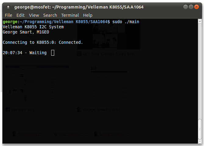
The Software running in a terminal window, 64-bit Ubuntu.