
Having got back into VHF SSB with my 144MHz Yagi beam, and having used Dave Mills (G7UVW)’s 432MHz ZL-special for UHF SSB work, I decided to make my own 432 MHz antenna.
Designing
The Yagi was designed using Martin Meserve’s VHF/UHF Yagi Antenna Design tools, as with the 144MHz Yagi.
The beam was designed for a resonant frequency of 432.2000 MHz at a drive impedance of  . This is typical for 70-centimetre SSB operation and is nicely compatible with my Yaesu FT-857D that I use for portable operation.
The beam was designed with a boom length of 1700 mm, purely as that is what I had laying on the workshop roof; it was square tube with an outside size of 20 mm square. The designed beam has 1 reflector, 1 driven element and 9 director elements, making a total of 11 elements. ARRL standards were adopted for reflector and element spacing, with all elements having an outer diameter of 6.3 mm, again due to this being the metal I had. The design shown below is for a bonded beam, meaning the elements are electrically connected to the boom at the element centre, which is in turn grounded via the coax shield. The estimated gain is 12.059 dBd.
The image below shows the design of the beam, and contains both the element length and cumulative spacing – everything you need to have ago!
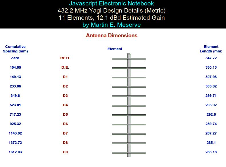
Note that this diagram is not to scale.
Specifications
| Frequency | Gain | Horizontal B.W | Vertical B.W | Electrical Boom Length | Boom Diameter | Element Diameter | Dimensional Tolerance |
| 432.2 MHz | 12.059 dBd (14.21 dBi) |
 |
 |
1700 mm | 20.3 mm square tube |
6.3 mm | 2.1 mm |
B.W = beam width. Boom must be at least the electrical boom length long.
Making
Dimensions Table
| Cumulative Spacing (mm) | Element Length (mm) | |
| REFL | 0 | 347.72 |
| D.E.* | 104.05* | 330.13* |
| Director 1 | 149.13 | 307.98 |
| Director 2 | 233.06 | 303.82 |
| Director 3 | 349.60 | 299.71 |
| Director 4 | 523.01 | 295.92 |
| Director 5 | 717.23 | 292.60 |
| Director 6 | 925.32 | 289.74 |
| Director 7 | 1143.82 | 287.27 |
| Director 8 | 1372.72 | 285.10 |
| Director 9 | 1612.03 | 283.18 |
- * The driven element is made as a folded dipole, and need not be made yet. See the Driven Element section below. I made this element, fixed it in, and then realised it was unnecessary!
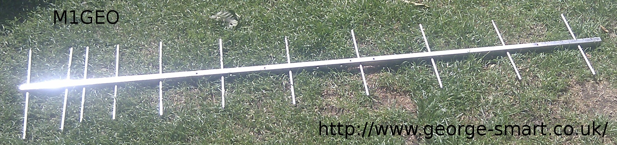
Making the beam was fairly straight forward. I marked two lines down the boom, on opposite sides, in the middle. Mark the position of the reflector (REFL on the above diagram). This is the reference of zero – everything else is measured along this line with respect to the reflector. From this, measure the other element locations, marking them out based on the dimensions table, above. Then repeat this on the other side of the boom. Cut the elements to length as specified in the dimensions table, above.
For this beam, I drilled the boom to take the elements directly, with a hole 0.1 mm smaller than the element diameter, I then used a clamp to push the element through the hole in the boom, making for a tight fit. As I used aluminium, this was an easy option, as I don’t have the tools to weld aluminium. I used a piece of heat-shrink on each side to stop the element sliding through the boom, should the interference fit become loose.
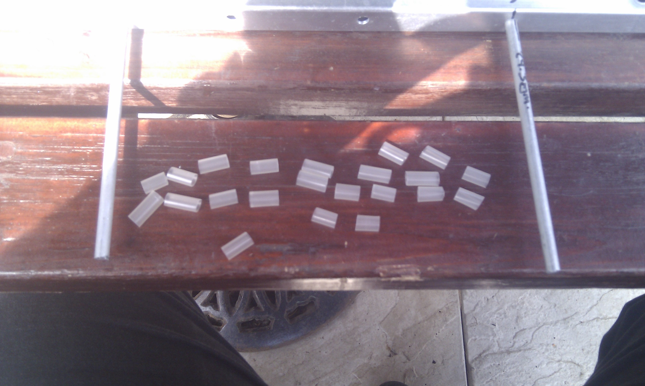
Centre up your element making sure the same amount is exposed on each side, then heat the heat-shrink tightly to the boom, so the element cannot move. Your beam should have taken shape, and at least look like an antenna…
As I said above, I made the driven element before I realised that a Gamma Match would not be suitable at UHF. For this reason, do not make the driven element as a normal element, but follow the section below!
Driven Element
On the 2 metre beam, I used a gamma matching section to match the co-axial cable to the feed point of the antenna. However, you quickly run into issues when trying to design one for 432 MHz. The gamma rod length is in the range of 10 mm long – obviously impractical!
Martin Meserve’s VHF/UHF Yagi Antenna Feed Design explains how to use a folded dipole as the driven element, which works out much better for UHF than the gamma matching section I used before.
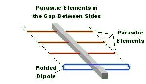
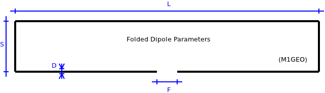
There are 4 parameters to the folded dipole, and they are shown on the diagram above. These are:
- L – The length of the driven element for resonance: here, 330.13 mm.
- S – The spacing. I used a value of 44.5 mm. This gave me enough room to get around the 20.3 mm boom, into the middle of the box, with a spacer on the back.
- F – The feed gap. This needs to be as small as possible. I made a spacer for physical support, with a spacing of approximately 5 mm. Should be smaller than the boom diameter (as a guide).
- D – Driven element diameter. This is in the range 0.681 mm to 13.627 mm from [http://www.k7mem.150m.com/Electronic_Notebook/antennas/yagi_vhf_feed.html]. Mine was 2.5 mm.
A folded dipole has a feed impedance of  , and so clearly something is required to convert from the of the driven element to the output of the radio. This is done with a
  (half-wavelength) matching loop.
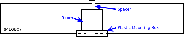
This matching loop (described below) is built into a plastic mounting box, and attached to the boom, providing support (along with a spacer) for the driven element, as shown below:
Matching Loop
Martin Meserve’s Feed page has a calculator for common co-ax types, but unfortunately mine was not on there. Check Martin Meserve’s Feed page for your coax to save yourself this maths.
I used UT-141. You need to know the velocity factor for your co-ax, to be able to calculate the physical length required for at the chosen frequency. The formula is pretty simple:
![\left [ \left ( \frac{3 \times 10^8}{f \times 10^6} \right) \times V_F \right ] = \lambda_{coax}](https://www.george-smart.co.uk/wordpress/wp-content/ql-cache/quicklatex.com-abdd7d9f5242c32536752cdbb88624b0_l3.png "Rendered by QuickLaTeX.com")
Where:
 is the frequency in MHz
 is the velocity factor for a given type of coax (the manufacturer tells you this)
 is the physical wavelength in the coax for a specified
As we’re interested in , we divide by two.
For the UT-141 I had, the velocity factor was given to be 0.694 (69.4%). For a frequency of 432.2 MHz, we can calculate and thus for our matching loop:
![\left [ \left ( \frac{3 \times 10^8}{432.2 \times 10^6} \right) \times 0.694 \right ] = \lambda_{coax} = 0.481721425 m](https://www.george-smart.co.uk/wordpress/wp-content/ql-cache/quicklatex.com-aa09dc114d893016b06f13b66771b68e_l3.png "Rendered by QuickLaTeX.com")

This matching loop is then configured as in the image below:
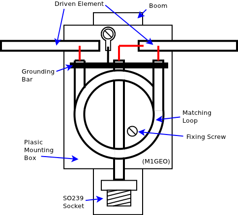
The 241 mm of coax (measured straight, over the shielded length only) is looped as shown to get it to fit inside the box. Make sure your coax doesn’t kink. Use something round of suitable diameter to coil hard-line coax around, or use cable ties to hold flexible coax in shape. All the coaxes need to have their shields connected together; this is done here by the “grounding bar”. This bar is also connected to the boom via a short wire and a solder tag. The feed coax (centre) connects to one side of the folded dipole (driven element) with one end of the matching loop. The other end of the matching loop connects to the other side of the folded dipole. The image below shows the physical construction of my matching loop in it’s overly sized box:
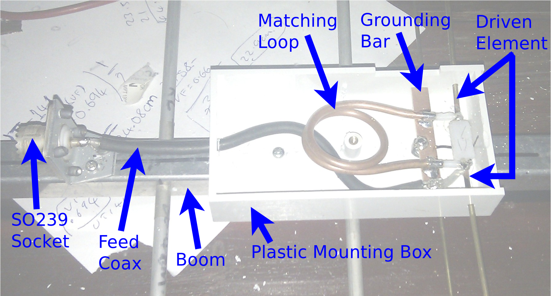
Note that the driven element is made from 2.5 mm brass brazing rod, and not from the 6.3 mm aluminium. This appears not to effect the performance too greatly from what I have seen.
Testing
The Yagi was tested in a similar way to that of the 2-metre beam. This time, all of the measurements were combined on to one graph. Click on the graph twice to make the image bigger (once to go to the image properties, and again for full resolution).
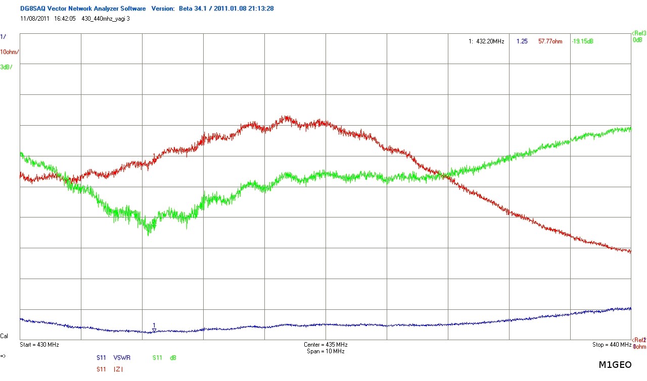
At the top right of the image, the marker values are displayed: F=432.2 MHz, VSWR=1.25:1,  .
.
The graph follows the same colour scheme as in the 2-metre beam testing. The red trace shows the feed point impedance. The green trace shows the antenna loss (i.e. what power is lost to freespace – or as we call it, radiated). The blue trace shows the VSWR. Marker 1 is visible on the blue (VSWR) trace, and is fixed at a frequency of 432.2 MHz. The frequency of SSB activity on the 70 centimetre band, and the frequency the beam was originally designed for. You can see at this frequency, the beam is radiating the most power (lowest point on the green trace).
I also measured the radiation pattern of this antenna as a separate project.
Conclusion
Although I was hoping for a slightly better VSWR, this is not possible. The matching loop does not have any adjustment. The obvious adjustment for the match is to adjust the length slightly. I suspect that some of the element lengths are very slightly due to the limitations in measuring equipment I have – I was only able to measure to the nearest millimetre, and this was done by eye; there was room for error. Finally, the beam was calculated to have a driven element diameter of 6.3 mm, but it ended up being 2.5 mm. I am unsure what difference this would make.
So, I suppose all said and done, I’ve had a few QSOs on this antenna already (on the day I built it – Tuesday 9th August 2011 – 70CMS UKAC monthly UHF SSB contest) and it performed well. I wasn’t able to get to my usual portable location so I had make do with my poor (low down) home QTH (QRA: JO01cn). Ultimately the beam took me about 4 hours to make, 2 more to test, and another 3 to measure the Antenna Radiation Pattern of it. It cost me nothing as it was made from scrap metal and kept me from trouble during the 4th day of London Riots.