All posts by M1GEO

Earth Fault on Yaesu G-5400B

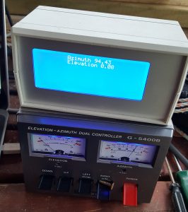
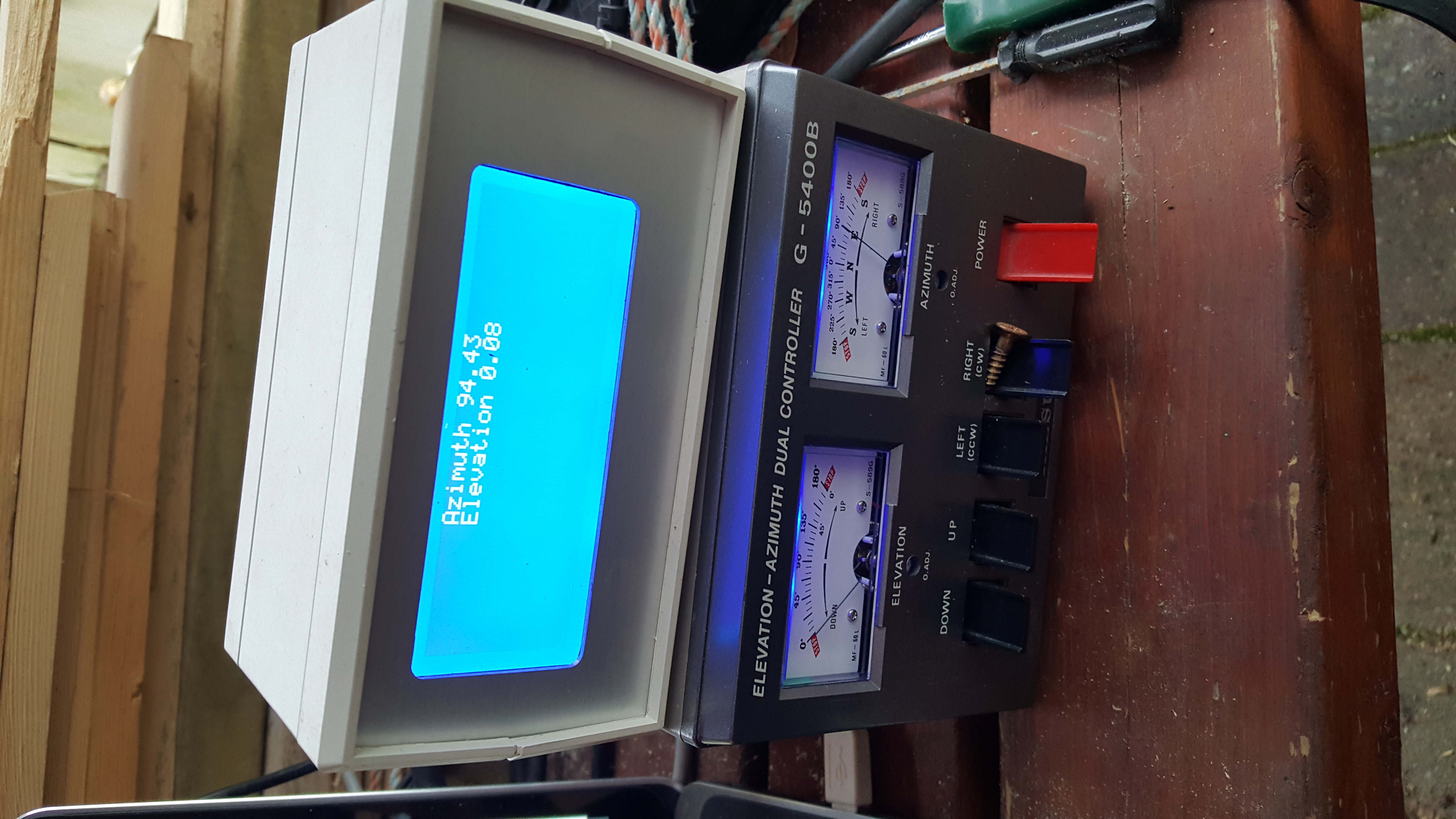
I brought a Yaesu G-5400B azimuth and elevation rotator & controller system from a friend at a local radio club about 6 months ago. I brought the rotator as faulty. When I powered the rotator up on the bench, I couldn’t find any fault. I built a PC-Rotator controller interface similar to the Yaesu GS-232 interface to accompany the G-5400B controller, and while doing extensive testing, no fault with the rotator became apparent.

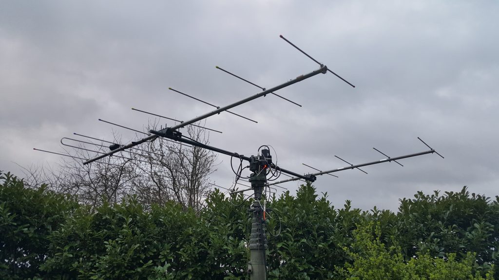
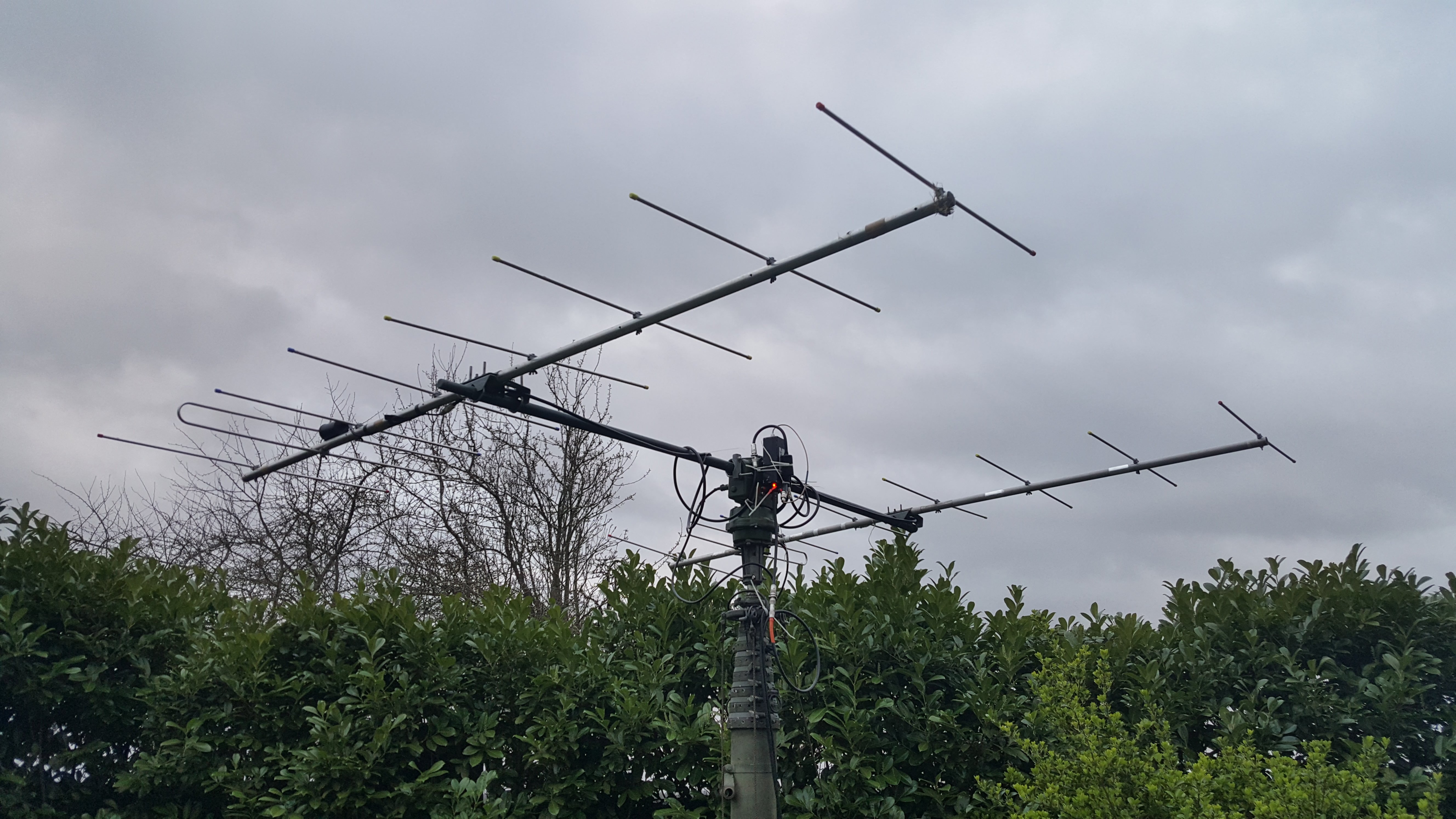
This weekend, following the acquisition of some fibreglass poles at the Rosmalen hamfest, I decided to set up my bayed 144 MHz beams with the azimuth/elevation rotator. After mounting the antennas on the beam, fixing the phasing harness and the mast-head preamp and connecting the cabling, I noticed that the rotator was no-longer working correctly. Although both of the rotators would turn, the azimuth display on the control box failed as soon as the coax was connected to the radio (or more specifically, the coax screen connected to anything in the shack that was earthed).

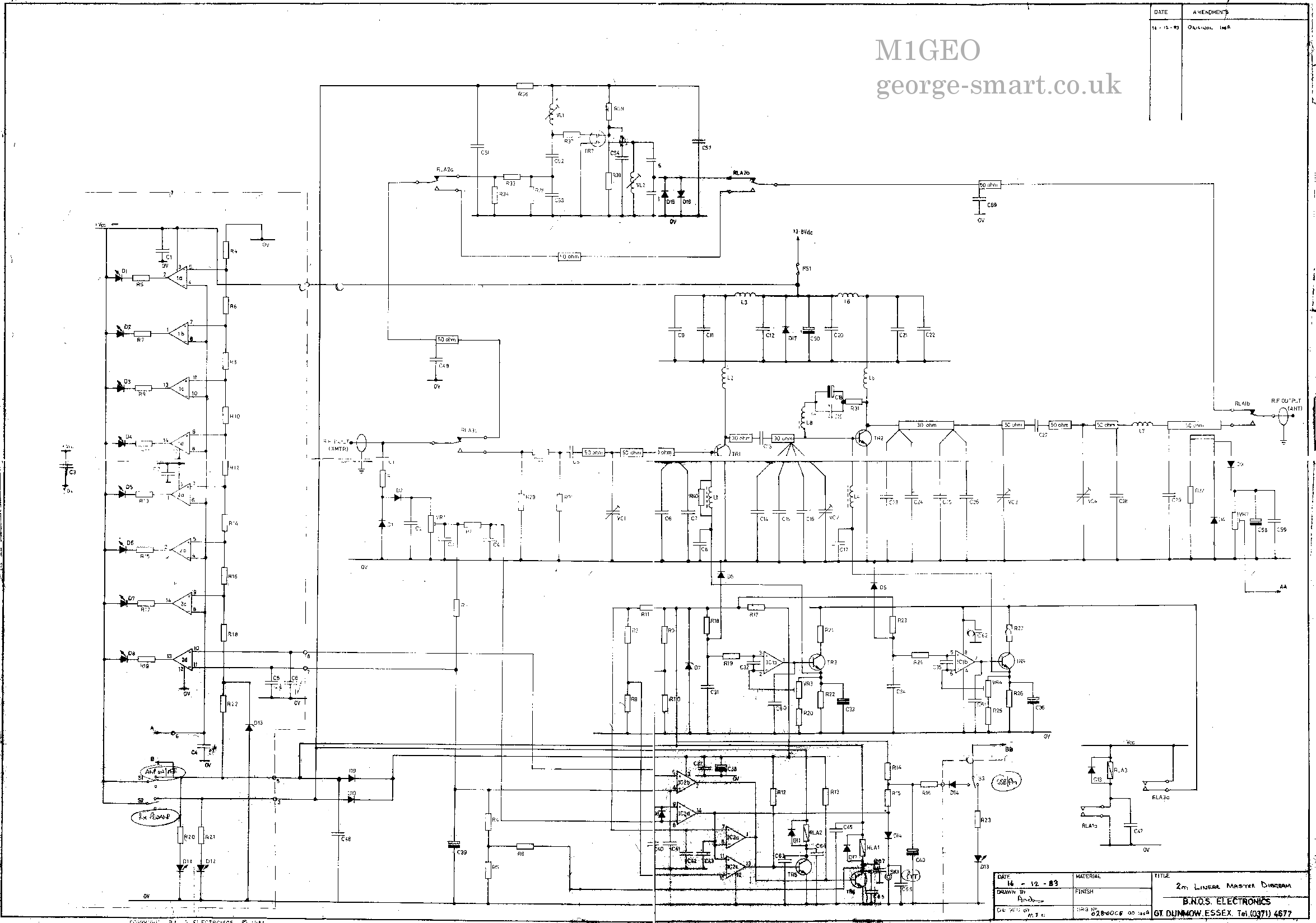
Using a multimeter to inspect what was going on, it was clear that the coax ground was sinking current sent to the potentiometer inside the azimuth rotator. Looking at the schematic, the cause would appear to be that the +6V side of the feedback potentiometer was somehow becoming shorted by the connection of the coax screen.

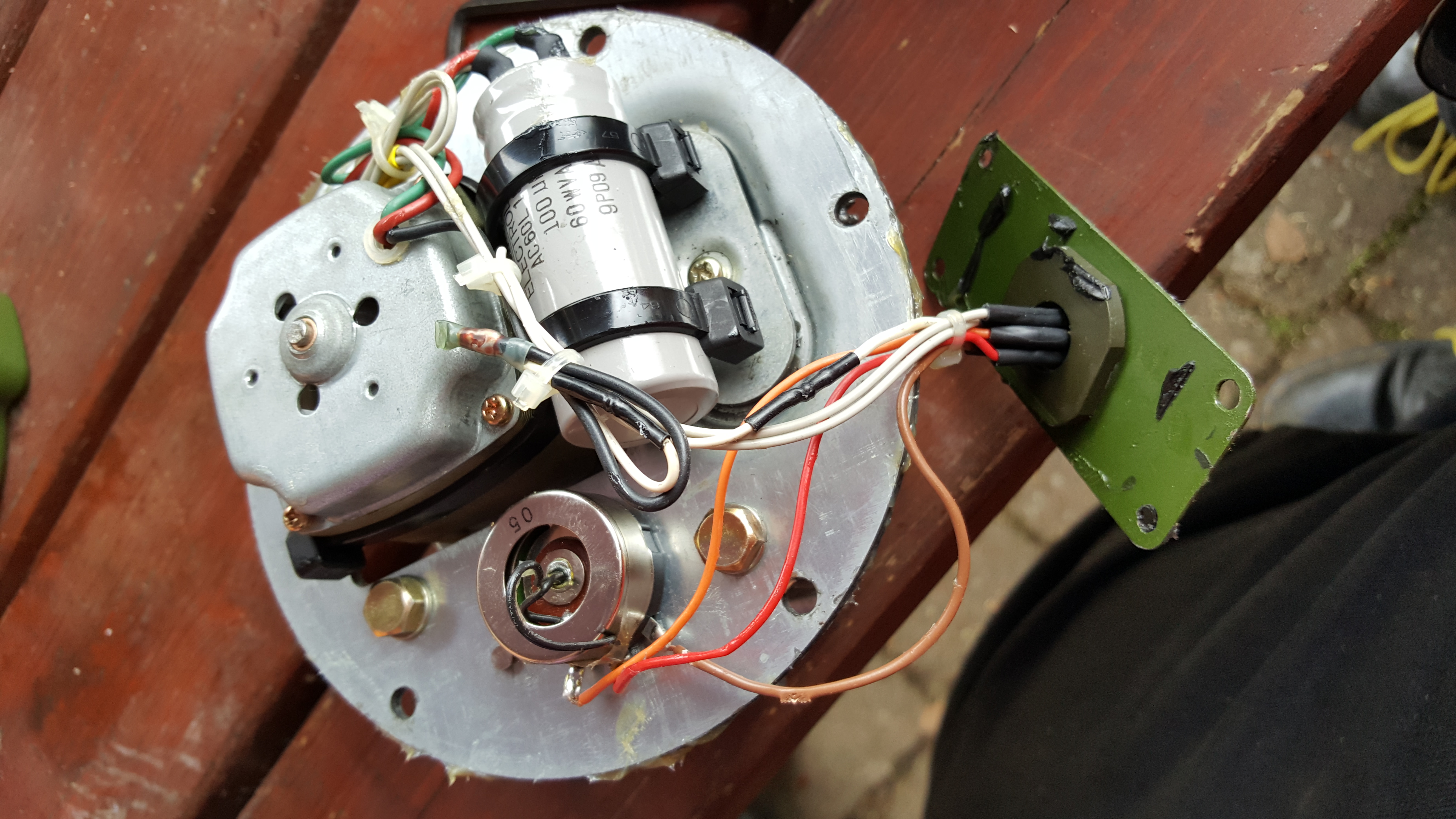
I decided to pop the cover and see what was going on

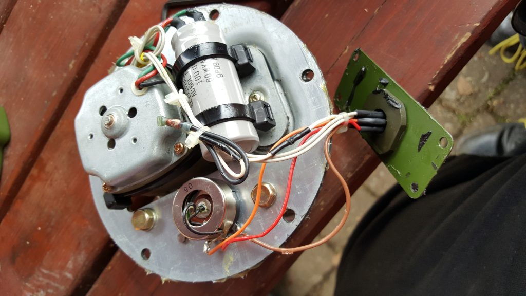
From inspection, you can see that the original hypothesis was correct and that one side of the potentiometer was shorting to the casting – the brown wire had been caught between the plate visible and mounting point. Since the antenna metal is grounded via the coax, this effectively shorted out via the broken insulation on the brown wire.

The repair was the simple process of snipping the broken wire, and soldering a new one in. I also used two tiny cable ties to bundle the wires to the potentiometer and to ensure they were kept away from the mounting hole, too.

The rotator goes back together easily assuming you have followed the usual advice when dismantling these rotators; marking the case and internal gear such that it can be reassembled with the same aligning.

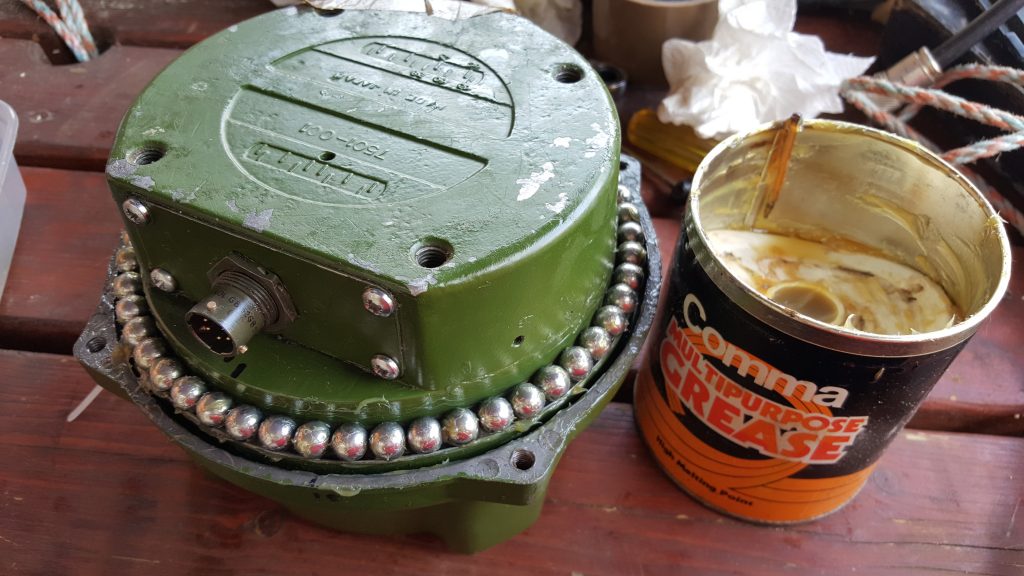
After finishing the reassembly of the the G-5400 rotator, being sure to grease the bearings, I was ready to mount the antennas and try again.

This time around, the rotator functioned perfectly. The total repair took around an hour. Now I need to finish the PC interface to make use of the fancy graphics LCD!

Machining Heatsinks for QRO Amplifiers

Back at the 2012 Friedrichshafen Hamfest I brought a 1.25 kiloWatt VHF amplifier kit for 144 MHz from F1JRD and F5CYS. These devices were fairly new at the time. It took me a year to pluck up the courage to build the pallet, but I went about it all wrong. With the help of Dad and the kitchen hob, we soldered the jrd1 Teflon PCB to the C110 copper heat-spreader as suggested in the Dubus article (see here). I had the pallet working at the time, giving around 600W of RF, which was about the maximum my 1000W 50V PSU was capable of sustaining. When I came to boxing the device up into an amplifier to use with EME and Meteor Scatter in late 2016, the part failed under test.

After much deliberation, I have ordered parts to repair the amplifier project. I found Jim W6PQL‘s website (see here) a wealth of information, and Jim also offers to supply parts and designs to help others. I ordered a set of PCBs to replace the original jrd1 board, a NXP/Ampleon BLF188XR 1400W part to replace the failed the Freescale/NXP MRFE6VP61K25H 1250W part, and some other accessories that Jim sells. The parts were posted by Jim today, so I decided it was time to recover parts from the old PCB and recondition the heatsink and heat-spreader.

The first step was to remove the jrd1 board from the copper heat-spreader. I used the kitchen hob to heat the copper heat-spreader, since the old board was soldered to the copper block. The board damage was sustained to enable the removal of the more expensive components.

Below, the heat-spreader with the jrd1 board removed. I used a solder sucker and scraper to remove as much of the molten solder.

Once the heat-spreader had cooled down, I mounted the copper spreader up in the milling machine read to re-machine the top and bottom surfaces. Great care was taken to level the block using parallels. Below you can see the fly-cutting process on the first cut, removing just 0.05mm from the surface.

With the top and bottom of the head-spreader machined flat, a small end-mill cutter was used to machine the transistor slot to the correct depth following the skimming of the top surface. Then the heatsink mating surface was machined. Below you see the first cut on the heatsink.

The finished parts. A few machining marks, but the surfaces are perfectly good enough. Some dents on the copper block, but it’s not worth removing all of the material to eliminate these.  Using a few drips of water as a substitute for thermal compound, the two mating surfaces stick together very well (with a good vacuum forming). That’s more than good enough for my needs!

Now I just need to wait for the parts to arrive before I can finalise the PCB and transistor mounting! This story continues here: Soldering Expensive Transistors.

Rosmalen Hamfest 2017

This weekend I drove to the 42nd Dutch National Radio Fleamarket hosted by the Bossche Radio Amateur Club and held in Rosmalen at the Autotron, Graafsebaan 133, 5284 The Netherlands.

This year, Dave G7UVW couldn’t make the trip, so Dave M0MBD jumped in at the last moment. In total, five of us were crammed in my car: Chris G8OCV, Peter G0IAP, Dave M0TAZ and Dave M0MBD and myself, M1GEO. Dave M0TAZ drove Peter G0IAP and Dave M0MBD from London to my home in south Norfolk. And from there we all headed to the Harwich International Ferry Port for our sailing at 23:00 to the Hook of Holland (courtesy of StenaLine). We always aim to arrive at the ferry early, put our luggage in our cabins, and then head to the bar for discussion and drinks!

In the morning, an all you can eat buffet starts the day well. The Rosmalen Autotron conference centre is about 50 minutes by car from the Hoek Van Holland port. After paying the entrance fee (€8, 2017) we were free to roam around from about 9am till 3pm when the conference centre closes.

As well as providing a great chance to purchase some parts for constructing projects, the hamfest also provides a good opportunity to catch up with friends from around western Europe. It was good to catch up with Niels PA1DSP and Pieter PA3FWM (of WebSDR fame), among many others.

Returning to the ferry terminal, we had a short wait before the check-in opened. We passed this time in the terminal building, using the remaining few Euro coins to buy coffee from the vending machine. Once we had boarded the ferry we offloaded our cases into our cabins once again and convened at the bar for a drink before our 3-course evening meal.

Another breakfast starts off the Sunday morning well. Departing the ferry at about 7am allows you to get home early and still have most of the day to yourself, to enjoy your hamfest purchases! All in all, the total cost of this year’s trip was £158 per person, including all food and fuel. Not too bad at all!

Portable HF Day & First Meteor Scatter Reception

After drying out from the RSGB IOTA contest last weekend, we took the gear out again 1-2 August, where I worked a few new contacts: 7Q7BP on CW was a firm favourite, as well as KH6/AA1LC in Hawaii, CY0/VA1AXC on Sable Is., 8P6FX in Barbados and CP6XE in Bolivia.

During the weekend we turned our hand towards the RSGB low-power backpackers contest working a few on 2m. After the contest, HA6KVC/P was coming through nicely via Meteor Scatter on FSK441.

This was the first time I have ever heard any meteor scatter… Ever…

Amateur Satellites & Dual-band Beams

Having attended a short talk by Steve M0SHQ at Essex Ham about operating Amateur Satellites, and seeing Steve work the ISS via APRS, I decided to have a go myself. I built the dual-band beam he recommended several times, but the design always measured up poorly. In the end I tweaked the design somewhat, and come up with something myself – it’s all credit to the original designer, I just optimised it with some antenna modelling software. Details on the antenna can be found here: Dual Band Satellite Yagi.

ircDDBGateway Basics

Over the past week or so, I have been playing around with DStarRepeater and ircDDBGateway to learn a bit about DSTAR repeaters, given the progress GB7KH‘s NoV is making. I have made a simplex hotspot with my FT817 and a soundcard interface, although I can see that there is certainly room for improvement. I have ordered a DVRPTR_V1 GMSK interface which has been dispatched so that will replace the soundcard, lowering the CPU load. I am to have the system set up on a Raspberry Pi 2 B, which was released yesterday (maybe today actually). I think I now understand how to tune up those Chinese notch filters, too.

DVRPTR_V1 inside board