
DCF77 is a longwave time signal and standard-frequency radio station transmitted from Mainflingen, about 25 km south-east of Frankfurt am Main, Germany (50°0â²56â³N 9°00â²39â³E). Some of the more technical details can be found on the Physikalisch-Technische Bundesanstalt website.
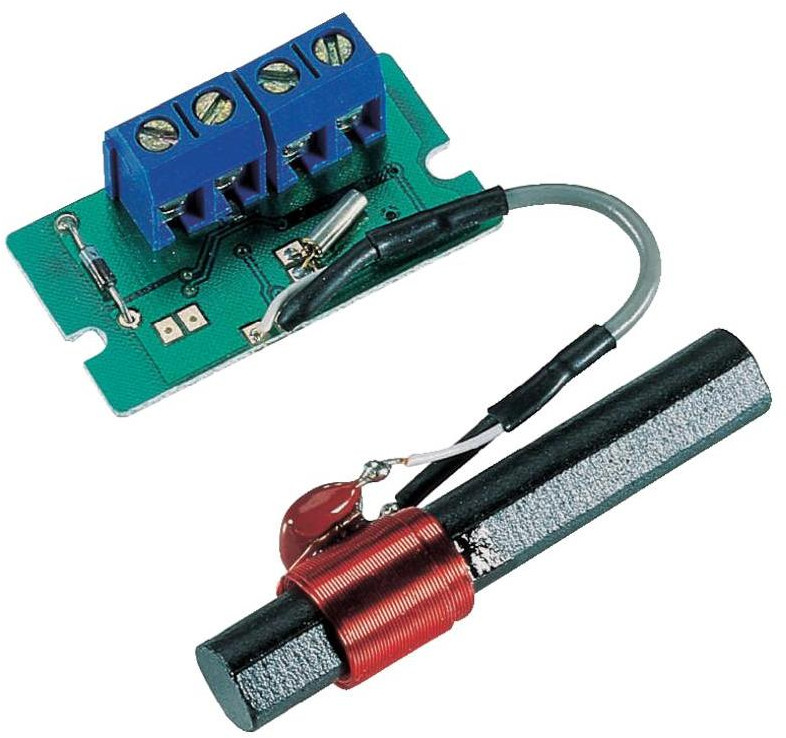
This page details some brief experiments with DCF77 reception in London. The receiver I used a Conrad DCF Receiver Board which is a complete DCF77 receiver with NPN open collector outputs, working on a large voltage range (1.2 – 15V) at around 3 mA according to the datasheet.
I had a nose around the internet, thinking that I would first try with an Arduino test bed. I found this excellent tutorial detailing Arduino interfacing signal recovery and an Arduino library. I set off playing!
I connected the power of the module to 5V and ground, with a  resistor to the open collector output of the receiver. I was ready to go:
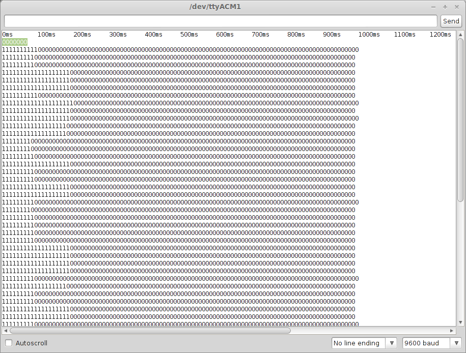
The first piece of Arduino code, lifted from here shows the state of the logic output of the DCF77 receiver. Ideally, there are series of pulses either 100 or 200 ms long every second. This code starts a new line every time a rising edge is received, and shows the logic state of the pin with time.
#define BLINKPIN 13
#define DCF77PIN 2int prevSensorValue=0;
void setup() {
Serial.begin(9600);
pinMode(DCF77PIN, INPUT);
pinMode(13, OUTPUT);
Serial.println(“0ms 100ms 200ms 300ms 400ms 500ms 600ms 700ms 800ms 900ms 1000ms 1100ms 1200ms”);
}void loop() {
int sensorValue = digitalRead(2);
if (sensorValue==1 && prevSensorValue==0) { Serial.println(“”); }
digitalWrite(BLINKPIN, sensorValue);
Serial.print(sensorValue);
prevSensorValue = sensorValue;
delay(10);
}
The below image shows the output of this code. You can see a selection of pulses ranging in time from ~100 ms to ~200 ms. The code timing is slightly out but is good enough at this stage. We can confirm that we are indeed receiving DCF77.
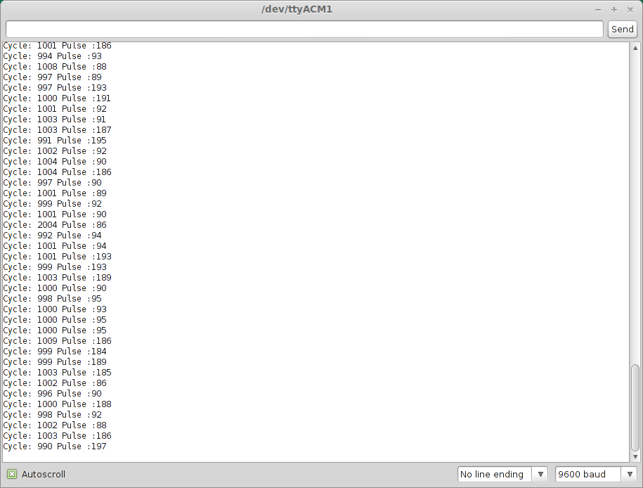
The next section of code shows the time between each rising edge (cycle) and the duration of the pulse (pulse). These two things are the key to decoding the data from the DCF77 signal. Code from here.
#define BLINKPIN 13
#define DCF77PIN 2int flankUp = 0;
int flankDown = 0;
int PreviousflankUp;
bool Up = false;void setup() {
Serial.begin(9600);
pinMode(DCF77PIN, INPUT);
pinMode(BLINKPIN, OUTPUT);
}void loop() {
int sensorValue = digitalRead(DCF77PIN);
if (sensorValue) {
if (!Up) {
flankUp=millis();
Up = true;
digitalWrite(BLINKPIN, HIGH);
}
} else {
if (Up) {
flankDown=millis();
Serial.print(“Cycle: “);
Serial.print(flankUp-PreviousflankUp);
Serial.print(” Pulse :”);
Serial.println(flankDown – flankUp);
PreviousflankUp = flankUp;
Up = false;
digitalWrite(BLINKPIN, LOW);
}
}
}
The image below shows the output again. As you can see the cycles last ~1000 ms (approximately) and pulses are either 100 or 200 ms.
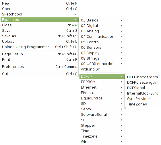
The next step was to get a copy of Thijs Elenbaas’s DCF77 library, at the time of writing, version 0.9.8. This was downloaded from this page or direct link. The library is installed like any other Arduino library see here. On my Linux system this was just to extract the downloaded DCF77.0.9.8.zip archive to /usr/share/arduino/libraries/. Once installed the examples from the libraries will be available to choose from within the Arduino IDE:
When trying to compile the DCF77 examples, I found that there was an issue with the bundled version of the Time library. Updating to the newest version here via here too me to this version of Time.zip. This was installed, but the error persisted. This forum post shows how to fix errors such as:
error: variable ‘monthStr1’ must be const in order to be put into read-only section by means of ‘__attribute__((progmem))’
I had to insert const into two places inside the file on the lines specified by the error. Hopefully all works well, and you’ll get the results you like. Below shows the TimeZones Example set to UK time (BST/British Summer Time):
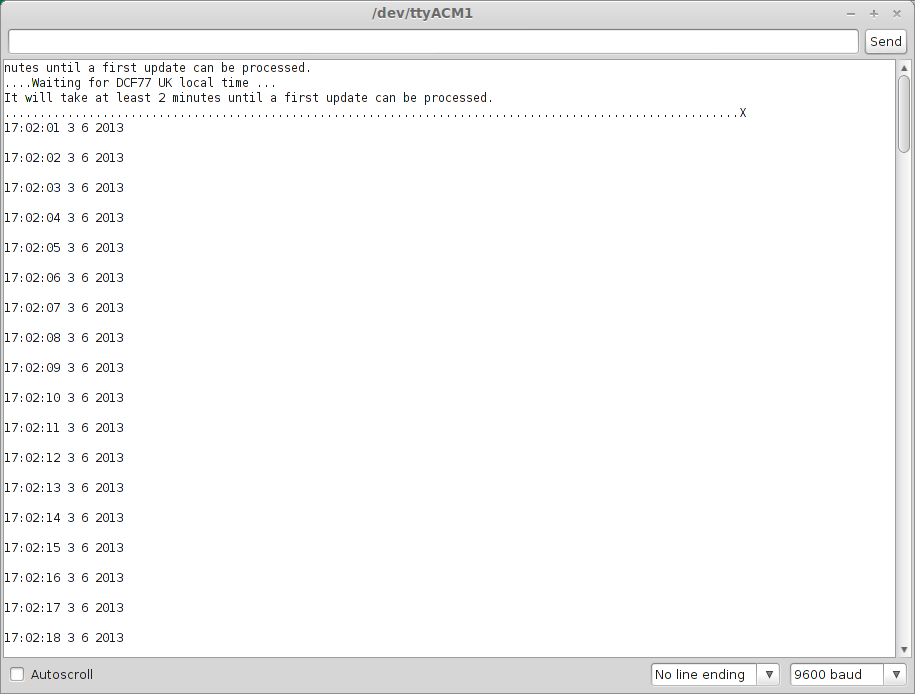
An extract from the first line shows the time to be correct when compared to my (ntp synced) desktop clock:
17:02:01 3 6 2013
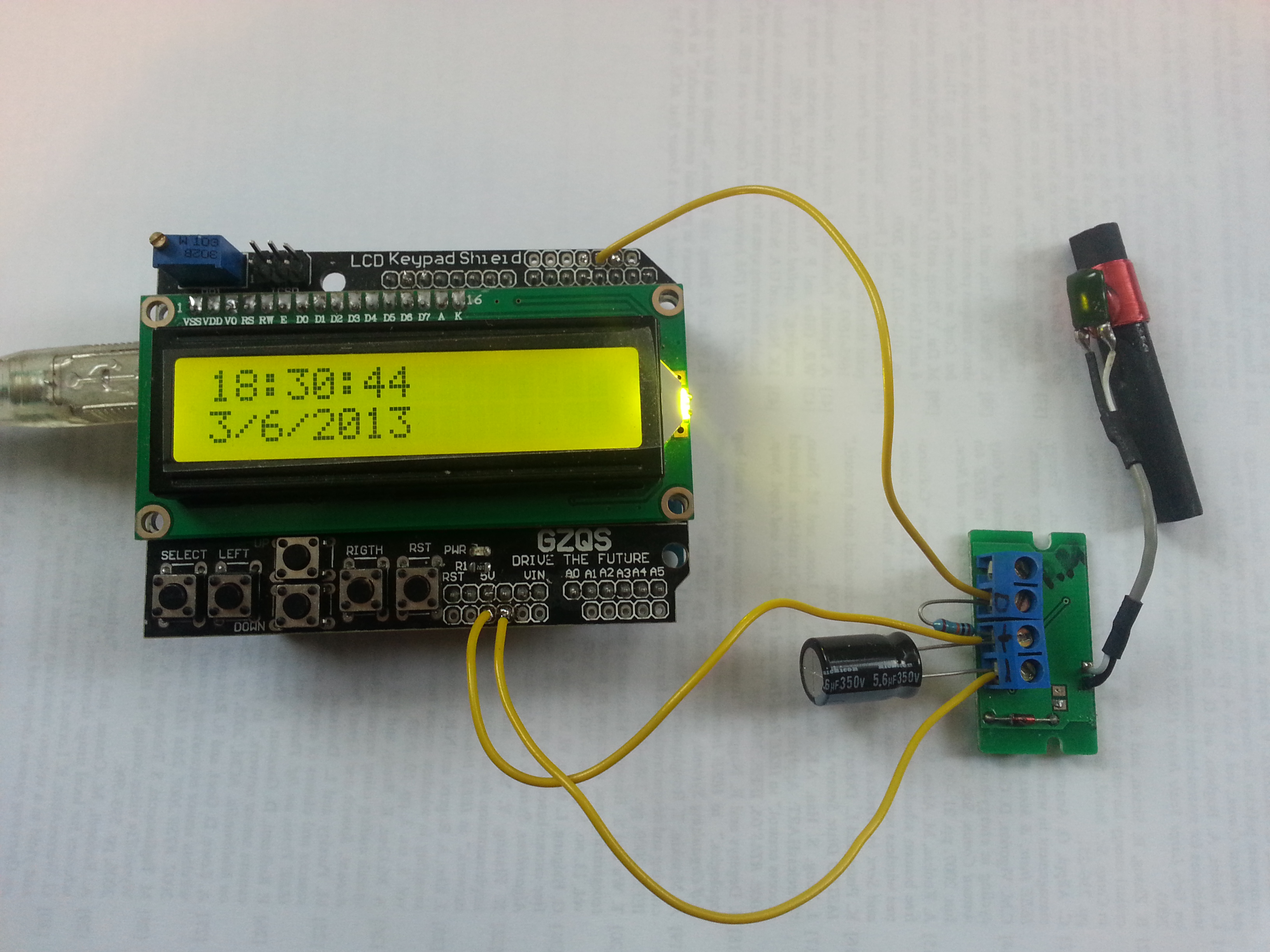
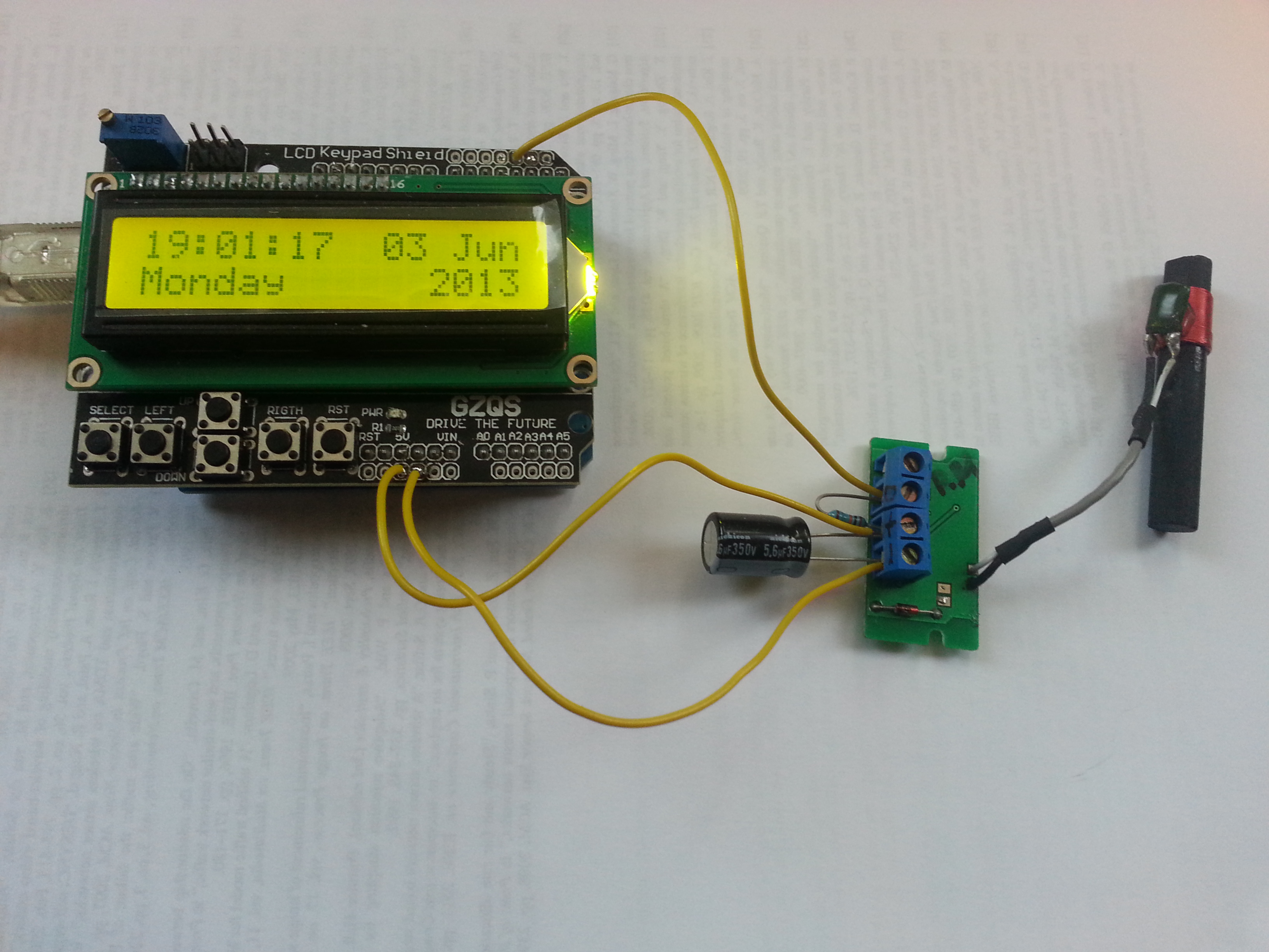
After some toying around, I managed to get the DCF77 decoded time to appear in a usable format on my Arduino LCD display. We also see that it took roughly an hour and a half for me to write a simple parser for the time! Shocking! Left shows the original attempt, and right shows around another half hour later, I have the formatting a bit nicer. Only so much you can do with a 2×16 LCD. The source code for the below project is here.
 |
 |
Great stuff. I’m hoping this may be the next step towards my Arduino WSPR MEPT. Currently I am using a GPS receiver and parsing the time with TinyGPS which works great, but uses much more power than the 3 mA quoted for the Conrad DCF Receiver Board.