
During VHF and UHF UKAC contests, conditions rapidly change. It is often useful to have a roger beep. Wiktionary defines a roger beep as:
A tone or tones added to the end of a broadcast segment to indicate that the user/operator has concluded speaking.
This design uses a Microchip PIC micro-controller (16F627A, 16F84A, etc) to read the signals sent by the radio and to generate the beep. I use a 16F627A as that’s what I have, but you can use any from that series, or the 16F84 series.
Schematic for the project:
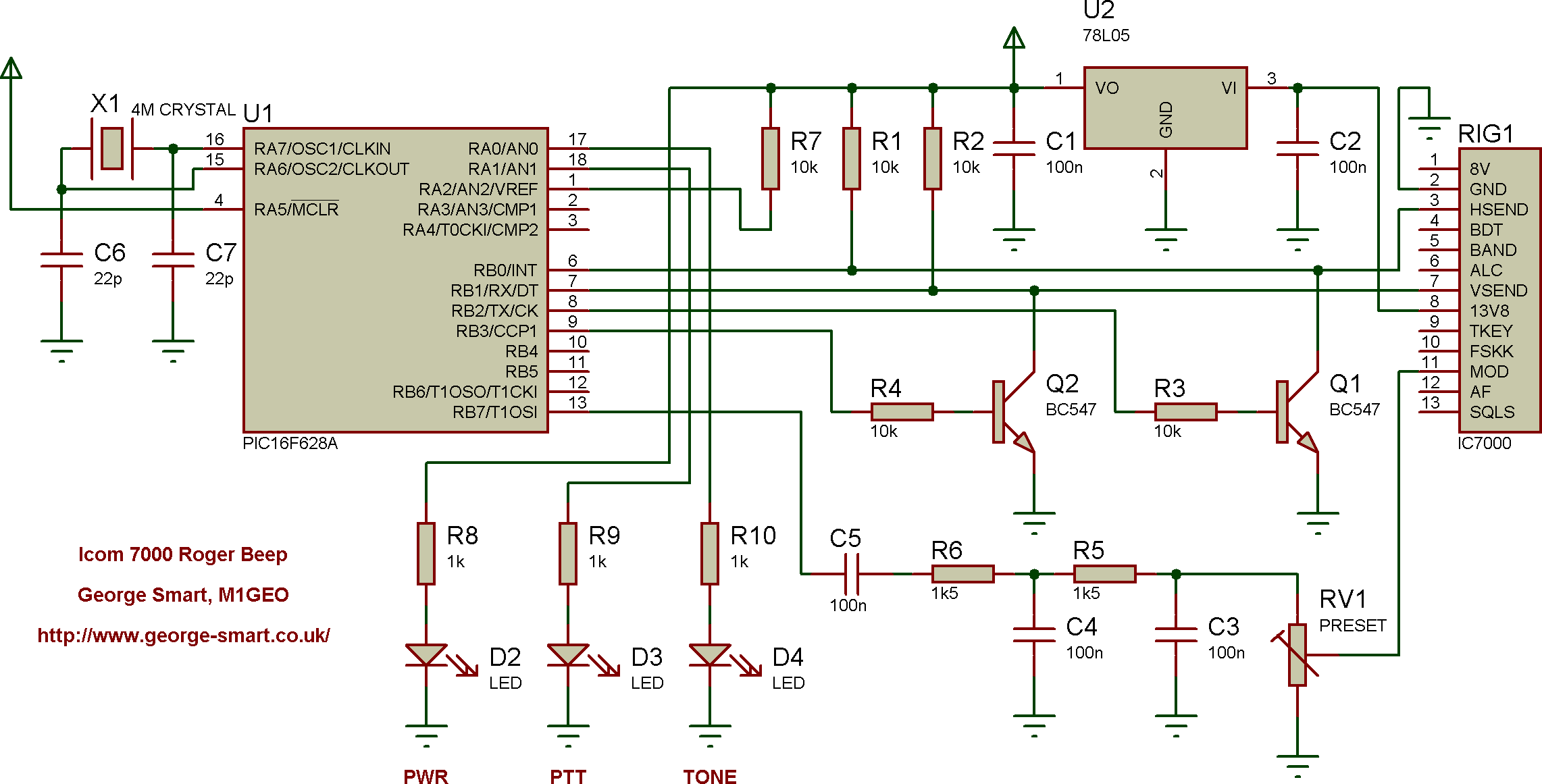
Components X1 and C6 & C7 can be ignored as they are not needed. The code for this project uses the PIC’s own internal oscillator, and does not require any external components.
Preset resistor pot RV1 is a 10K linear pot.
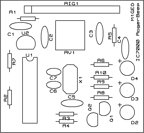
The PCB layout and copper mask can be found below. Also available is the Gerber/Excellon files in ZIP format. The PNG images are scaled correctly at 300 DPI and the PDFs should be printed at 100% scaling on A4 paper.
 |
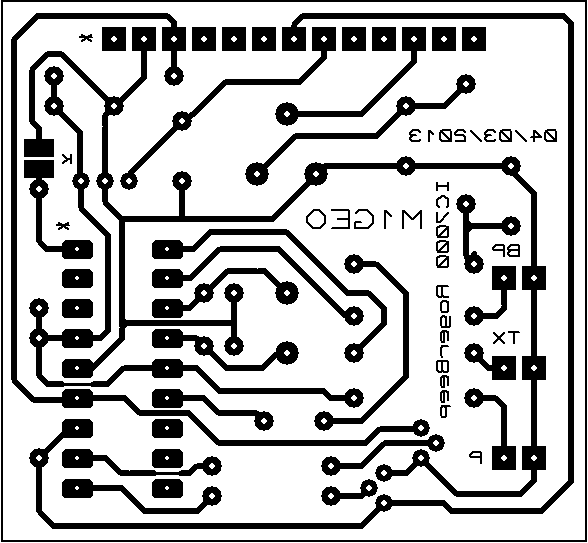 |
| Silk Screen at 300 DPI | Copper Mask at 300 DPI |
| Silk Screen PDF (A4 100%) | Copper Mask PDF (A4 100%) |
The only connection between the radio and this circuit is made via the accessory socket. The device is powered via the radio, so it will pay to thoroughly test this project before connecting it up to the radio. Currently the only setting is the variable resistor, which sets the tone’s amplitude. This is set such that the ALC on the transmit reaches full, but does not over drive. Follow the radio manual’s instructions for using DATA modes to set the level. Of the 13 pins in the ACC socket, only 5 are used.
The block diagram shows the basic functionality.
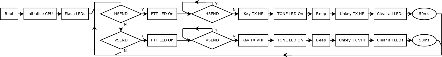
When the project is first powered, all the LEDs flash to show the CPU is running. In the idle state, just the power LED is on. When the radio is keyed (via any method) either the VSEND (VHF) or HSEND (HF) line is toggled by the radio. The CPU detects that change and puts on the PTT LED to show the roger beep project is aware of the radio’s transmitting status. When you de-key the transmitter, the CPU again detects this change. At this point, the project immediately re-keys the radio and creates the beep tone. This lasts a short period and then the radio is again de-keyed. This is fully automatic.
The hex file for the Microchip PIC 16F627A can be found here: RogerBeep 16F627 Firmware (ZIP/HEX). The HEX file is zipped as it is easily accepted by my website’s CMS. If you require a slightly modified functionality then this hardware should provide an easy enough platform for you to experiment with your own firmwares inside the PIC MCU.
The LEDs are for debugging and are not required, so feel free to omit these if you don’t need them.
Finally, a short video of the project working.