
Before you get too stuck into this page, please bear a few things in mind:
- Much of this page is my interpretation of the datasheet. I could have misunderstood something, or I could have completely got something wrong. Don’t take this page as gospel. If you think anything is wrong, then contact me: Feel free to send feedback, suggestions, corrections.
- If you find this page useful, please consider donating a small sum of money (of your choosing) to help fund my time and the upkeep of this server. This site is run entirely out of my own pocket, with no advertising because that’s how I feel it should be. Anything you could spare would make a difference.
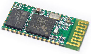
The WLS123A1M RS232 Bluetooth module was bought for me as a present by Aaron Brown from Seeed Studio. It was a little hard to get the device going, and the instructions a little hard to follow so I decided to document my results with the module here. I also developed an Arduino Shield for the device, which can be found further down this page.
Documentation
The part was purchased from SeeedStudio, and can be found here: Serial Port Bluetooth Module (Master/Slave). The Serial Port Bluetooth Module (Master/Slave) Wiki Page has some basic information, but the key to success for me was in the Bluetooth Module Manual v1.2.pdf document. There is also some interesting discussion on the forums of SeeedStudio, here: Set up connections between two BluetoothBee step by step.
Arduino Shield – Connecting It Up
As mentioned previously, I made an Arduino Shield for the WLS123A1M Bluetooth RS232 Module. The PCB layout is available for you to do as you please, in line with my standard Disclaimer & Copyright.
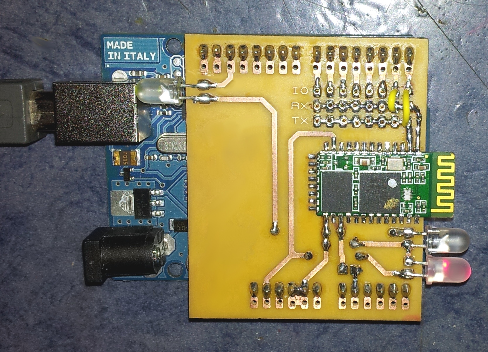
With my Arduino shield it is possible to connect the bluetooth module directly to the FTDI chip. The Arduino device was programmed to just flash an LED (digital #13) so it left the serial communications lines. Simply connecting the RS232 UART lines of the bluetooth module to the TX/RX lines of the Arduino does the trick: Arduino-RX to Bluetooth-TX and visa-versa allows them to communicate (This may not be true when communicating from the Arduino’s MCU and not FTDI-USB – check the connections!).
Signal PIO1 (pin #24) gives a status instruction port; high when connected, low when disconnected. Signals PIO10 (pin #33) and PIO11 (pin #34) also give indications to the modules status. See the Software Features section of the device’s datasheet for more details on their intended use.
Talking to the Module
The biggest thing to remember is that the WLS123A1M Bluetooth Module expects a carriage-return (\r) and line-feed (\n) combination (\r\n) before and after every command. To ensure this, I always sent a blank like before I entered the command, and once again after it. Sending too many \r\n sequences does not cause any problems. Not sending enough causes lots of errors. The logic inputs are TTL inputs, supposedly at 3.3v. The data-sheet says they will tolerate 5V logic from the FTDI/Atmel chips, and in my experience do.
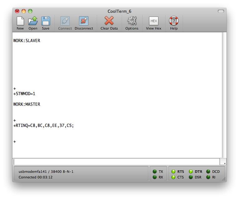
I used two computers to develop with the WLS123A1M module. My Apple MacBook Pro was used on the USB side of the Arduino board, as the local control of the board. My Ubuntu desktop machine was used to connect with the module via bluetooth. On the MacBook, I used a program called CoolTerm to act as a dump terminal, and the standard Mac OS X drivers were used to communicate with the Arduino’s FTDI chipset. The default speed of this specific model was 38400 bps, but this can be changed in software (see the +INBD command).
Presented below is a mixture of my own experience and what various data-sheets claim. If a command is mentioned in the datasheet and not in this section, it means I haven’t personally tried it. Any changes made to these settings are retained even when the device is powered off.
Commands for Setting Up
It is also important to note that the module has two separate modes: Master and Slave. Changing between these is the first topic of discussion.
Mode (STWMOD)
The WLS123A1M module has two separate modes: Master and Slave modes. In master mode, it is the module that initiates connections, requiring it to scan for slave devices. In slave mode the module broadcasts itself as being available and waits for a master device to initiate a connection with it. These modules are in one state or another, they cannot be in both at the same time (that I know of), where as a PC can be. In my brief experience with the module, it seems to be easier (at least for what I am doing) to use slave mode, thus transferring the control to the more powerful device (such as a PC) with a better user interface.
To set the device into Master (server) mode, you would send the following command:
\r\n+STWMOD=1\r\n
To set the device into Slave (client) mode, you would send:
\r\n+STWMOD=0\r\n
The module will respond with
WORK:MASTER
or
WORK:SLAVER
Accordingly.
Flowcharts
Just as a brief note between the two modes: the expected flowcharts are as follows:
Master
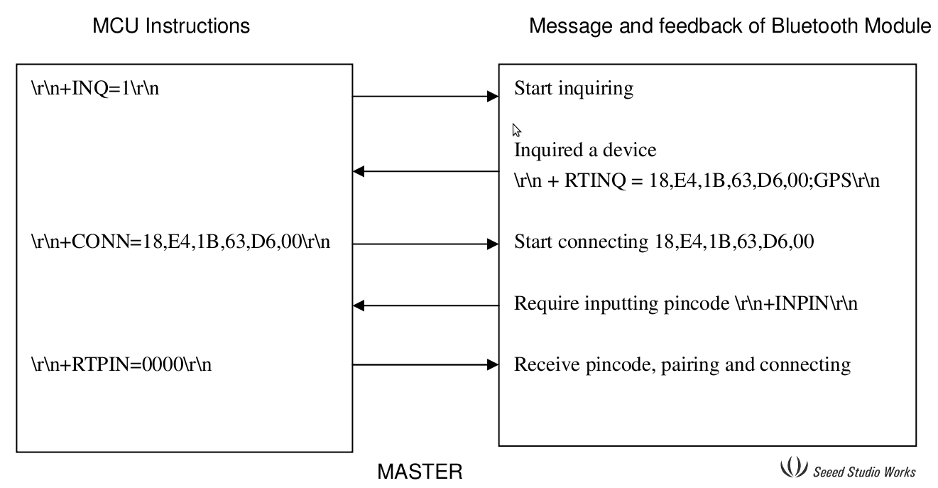
In master mode, the module starts by inquring – scanning – for devices to connect to (those appearing in slave mode). The module will return the MAC addresses of available devices and, where possible, their names. The module then issues a connect request to a specific MAC address. An exchange of PIN numbers occurs then before the two devices are paired and ready for connections.
Slave
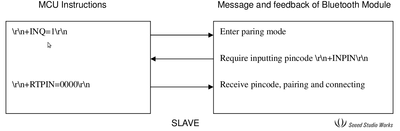
In slave mode, the device offers itself for connection – broadcasts itself – to those master devices that are inquiring. When a connection is requested of the slave device, it is asked for a PIN number which is exchanged and the process continues as with master mode. The devices are paired and ready for connections.
Baud Rate (STBD)
Sending
\r\n+STBD=115200\r\n
changes the communications rate from the current setting to the supplied value of 115200 bps. The default is 38400. Available values are 9600, 19200, 38400, 57600, 115200, 230400, 460800. I have successfully used speeds up to and including 115200. This setting is remembered when the module is power-cycled.
Device Name (STNA)
Sending
\r\n+STNA=ArduinoTest\r\n
sets the device’s broadcast name to “ArduinoTest”. I am not sure what the length limit is, but everything I tried worked fine. I assume you would get an error message if the string was too long – you seem to get them for almost anything else 🙂
Allow Connections (STOAUT)
To allow paired devices to connect to the device you need to permit paired devices to connect. To allow them, send
\r\n+STOAUT=1\r\n
Or to disallow connections from paired devices, send
\r\n+STOAUT=0\r\n
Set Pincode (STPIN)
This is the pincode required to pair with the device when in master mode. The PIN is a 4-digit number; for example to set a pin of ‘1234’ send
\r\n+STPIN=1234\r\n
It is removed with the delete Pincode (DLPIN) command, see below. This pin may also be the default try before sending the INPIN PIN request – I am not sure though.
Delete Pincode (DLPIN)
This removes a Pincode set with STPIN, as above. It takes no arguments. To remove the pincode, send
\r\n+DLPIN\r\n
Read Local Address (RTADDR)
This returns the MAC address of the module. I could only get it working in master mode, but the MAC should be the same in slave mode too. Mine was. It should be. To get yours, send:
\r\n+RTADDR\r\n
Commands for Normal Operation
Inquire (INQ)
The inquire function operates differently depending on which mode the module is in. In master mode, it causes the module to scan for devices that can be connected to. In slave mode, it initiates broadcasting of the device’s name (STNA) for master-mode devices to connect to.
Master
To start scanning for devices:
\r\n+INQ=1\r\n
And, to stop scanning:
\r\n+INQ=0\r\n
When the inquiry finishes, devices are returned in the following way:
\r\n+RTINQ=aa,bb,cc,dd,ee,ff;name\r\n
This would be the response for a device with MAC address: AA:BB:CC:DD:EE:FF and the name “name”
Slave
To start broadcasting to devices (to become visible to others):
\r\n+INQ=1\r\n
And, to stop broadcasting:
\r\n+INQ=0\r\n
Connect to Device (CONN)
To connect to device with MAC address AA:BB:CC:DD:EE:FF, you would need to send:
\r\n+CONN=aa,bb,cc,dd,ee,ff\r\n
Pincode Request (INPIN)
If your connection should require a Pincode, the module will send an INPIN command, as below:
\r\n+INPINr\n
To which you follow with an RTPIN command, as below.
Input Pincode (RTPIN)
This is in response to being asked for a PIN, such as an INPIN request is received. If you wish to respond with a PIN of 0000 such as is typical, then you would send the following:
\r\n+RTPIN=0000\r\n
Disconnecting (PIO0)
Disconnecting is done via a hardware logic signal on pin PIO0 (pin #23 on the device). Taking this line high causes the module to disconnect.
Return Status (RTSTA)
This is the return status from the module. It is not a command.
\r\n+RTSTA:XX\r\n
where XX is the status code from:
- 0 – Initialising
- 1 – Ready
- 2 – Inquiring
- 3 – Connecting
- 4 – Connected
Pin PIO1 (pin #24 on the device) also goes high when the module is connected to a device via Bluetooth. The PIO10 (pin #33) and PIO11 (pin #34) can also be used for statistics outputs. These provide useful places to connect status LEDs. See the Software Features section of the device’s datasheet for more details on their intended use.
Pairing with the Module
Below are a few examples of pairing with the WLS123A1M Bluetooth Module under Mac OS X Snow Leopard and Ubuntu 10.04.3 LTS. These images were taken with the Arduino in slave mode, and having set the device into broadcast mode (slave-mode; INQ=1). This allows the module to be findable.
Mac OS X
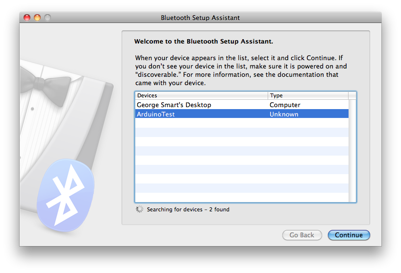
Once you’ve got the device paired, you can connect to the device in the standard Mac Bluetooth way. This will create you a virtual comm port for the bluetooth device, something like /dev/ArduinoTest-Dev – this may vary. This can be used as a comm port as you ordinarily use one, such as with a terminal program to send RS232.
Ubuntu 10.04.3 LTS
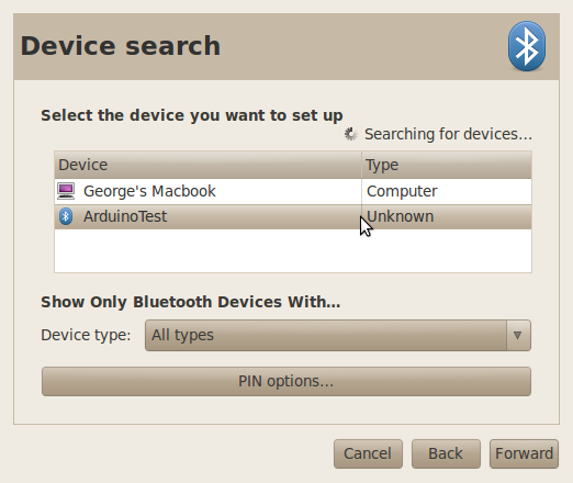
Under Linux it is not quite as straight forward, though you get a lot more choice. The process of getting a bluetooth comm port is standard and well documented, but I will explain it here for completeness.
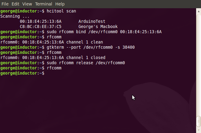
The above image summarises the steps, but here they are again with a little more explanation.
The first thing we will need to do is to find out the MAC address of the Bluetooth module. We use the following command to scan for devices.
hcitool scan
The image above shows it returning two devices; ArduinoTest and George’s Macbook. ArduinoTest is the name I gave the module (via STNA). We see the MAC address for ArduinoTest is 00:18:E4:25:13:6A. We then use the rfcomm tool to create a virtual comm port. rfcomm uses device nodes in the style rfcommX where X is an integer. The first device is /dev/rfcomm0, which we use here. The bind option tells it to link the MAC address 00:18:E4:25:13:6A with the device node /dev/rfcomm0. This is run as root.
sudo rfcomm bind /dev/rfcomm0 00:18:E4:25:13:6A
We can check it worked out by running rfcomm and seeing the output.
rfcomm
We see it tells us that rfcomm0 is linked to our MAC address and the state is clean (we know we’re also on channel 1, should it matter to us). At this point, /dev/rfcomm0 acts just like any other serial terminal device. It can be treated exactly the same as a hardware port, such as /dev/ttyS0 or /dev/ttyUSB0. Note: The bluetooth connection is not established until you open the port. When you close the port (drop use of /dev/rfcomm0) the bluetooth connection is also dropped.
Running rfcomm at any time will tell you the state of the virtual bluetooth comm port. When you no longer require the device node, you can free (release) it with the following command (run as root):
sudo rfcomm release /dev/rfcomm0
Running rfcomm now will return nothing, as no virtual comm ports exist.
Using this method, the following data transfer test was done.
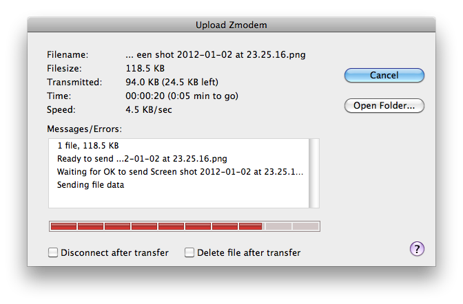
Data Transfer
Once the devices are paired and connected, the system acts just like an RS232 link between the two devices. I decided to try and put the system to actual use; I decided to try some data transfer using the Z-Modem binary data transfer between Mac and Ubuntu machines. The screenshots from the Mac were all sent over the Bluetooth module via Z-Modem, The first image shows the Mac sending the image via ZOC which supports Z-Modem on Mac.
The next image shows the reception of the above image transmission using Minicom which also supports Z-Modem under Linux.
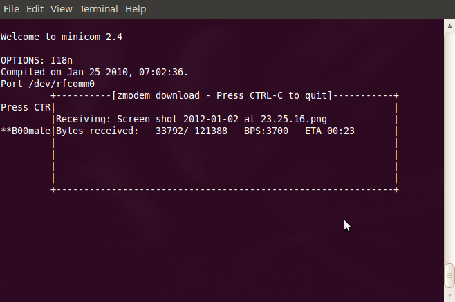
All images from OS X were transferred this way before being put online.