
The Jupiter 12 GPS Receiver has a 10 kHz output which is GPS locked. This page is about my project to make this into a 10 MHz frequency standard. This involved building a simple phase-locked-loop (PLL) which uses the super-accurate 10 kHz from the GPS as a reference for a 10 MHz VCO.
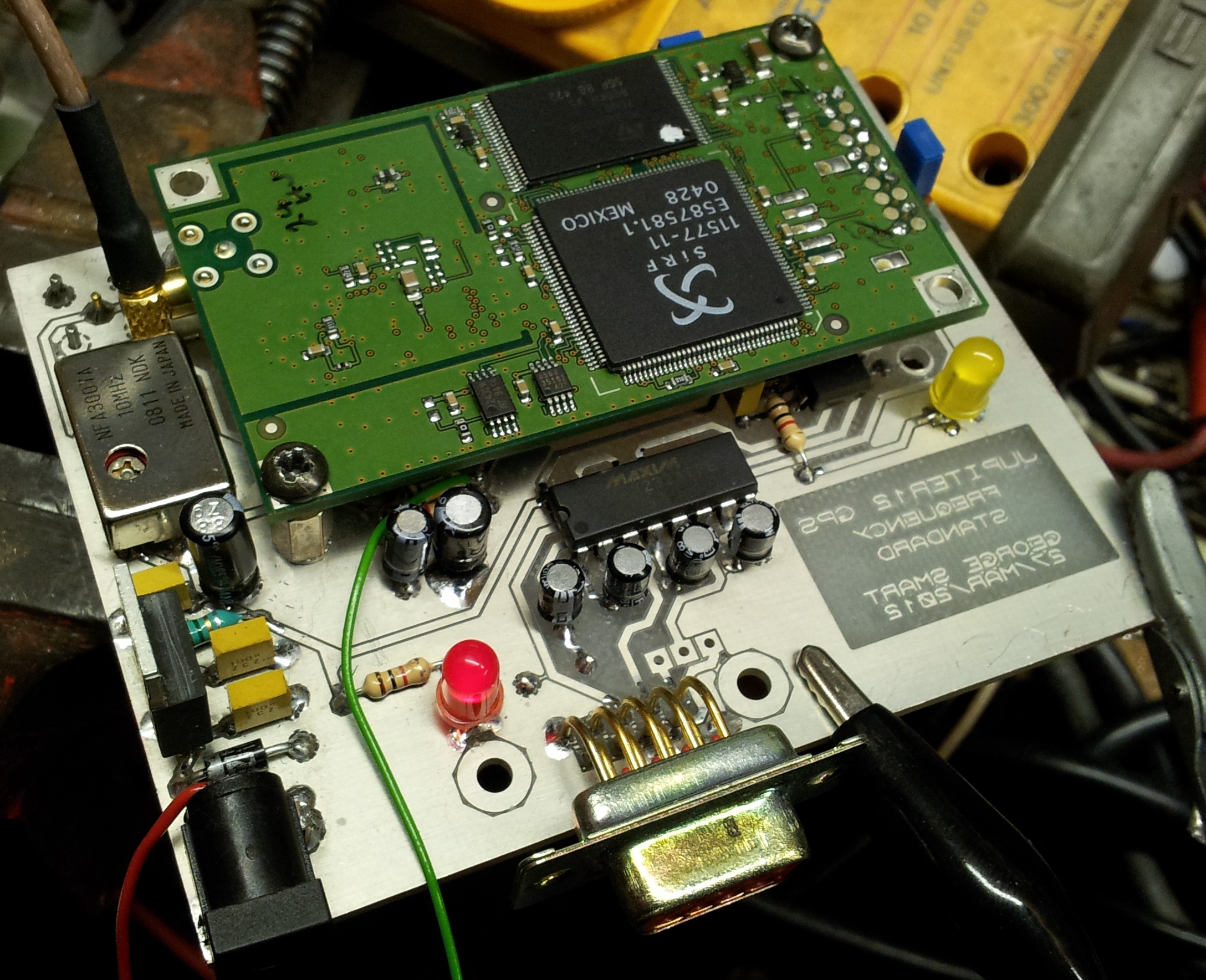
You can see the green board is the Jupiter 12 GPS Receiver. The (upside-down) board underneath is the GPS Frequency Standard. The PLL circuit is under the Jupiter board. The board also has a DB9 connector for data connections to the Jupiter board, with MAX232 for true RS232 connectivity. The Jupiter board supports standard NEMA 4800 bauds as well as Zodiac binary format. See the Jupiter 12 datasheet for more on the data formats. There is a hard link to force NEMA, while gpsd will read almost all GPS data formats (including NEMA and Zodiac binary).
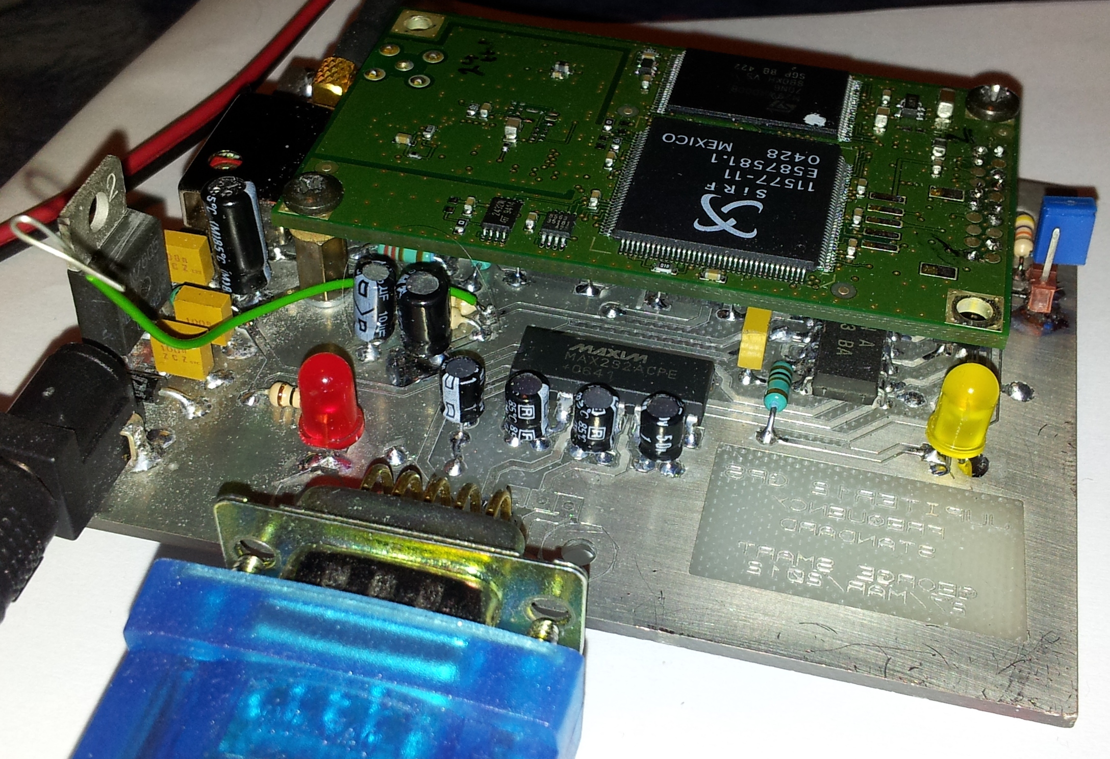
The green wire sticking up is the output of the phase-detector and used for testing. It has been removed since the testing stage.
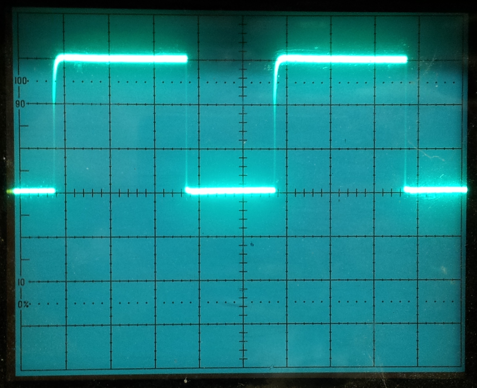
The above image shows the 10 MHz output. The schematic design presented below has been adjusted for better duty cycle; closer to 50%. The signal is about 5V pk-pk. The output has a source impedance of 50 Ohms.
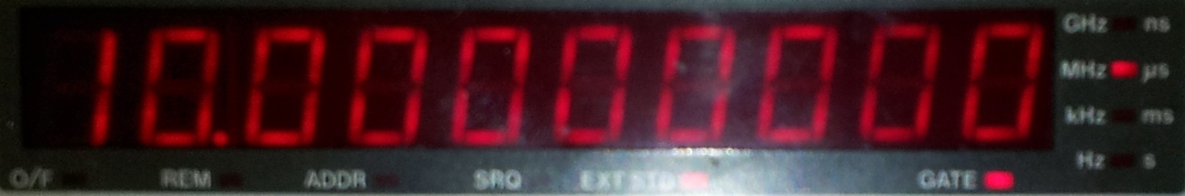
Finally, I wanted to check this design against a known good frequency source, to see if we really have achieved the goal. As is evident from the image above, the frequency is accurate down to 10 mHz (milli Hertz). There is a little phase noise on the signal which is usually present on GPS frequency standards, and on these small VCO modules. Here, the reference is a professionally (and very expensive) Trimble GPS Frequency Standard such as those used to frequency lock large transmitters.
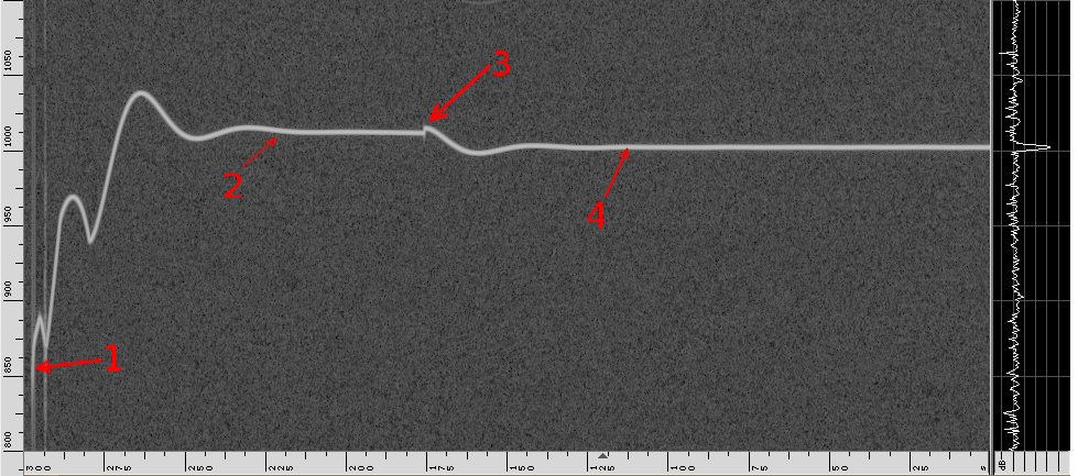
Above, the spectrograph of the designed GPS frequency standard locking for the first time. There are 4 salient points in this process:
- The power is turned on
- The VCO gradually pulls in to lock with the GPS’s reference (which is currently unlocked from GPS).
- The GPS 10 kHz locks, and the VCO then re-locks to the new GPS frequency reference.
- The system is locked and the output a good 10 MHz; ready to use!
The Design
The design is presented here for you to do with it what you like. It’s offered in the hope that it may be useful. Read the disclaimer and copyright if you’re concerned. If in doubt ask. If you’re making it for yourself then it’s fine. Go ahead.
| PDFs | PNGs (300dpi) |
| Schematic | Schematic |
| Copper Mask | Copper Mask |
| Links Layer | Links Layer |
| Parts Layout | Parts Layout |
| Bill of Parts | Only as PDF |