
Building your own
If you are interested in creating your own version of this project, please contact me as I have spare PCBs. At the current time, you will need to create your own character grid (cut vinyl, printed acetate, laser cut black card, or cutting by hand with a craft knife) and light mesh.
All design files can be found at the end of the page in the Downloads Section.
About the project
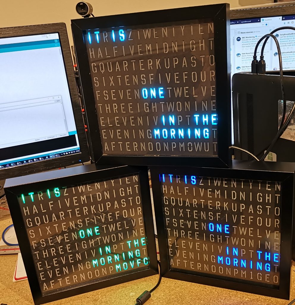
In the past I have really enjoyed making clocks of various kinds – mostly Nixie clocks. I had seen ‘Word Clocks’ appear in searches and had though of making them in the past. Looking around on the net, there were lots of people who had made hack-y versions that were a one-off: with hot glue and balsa wood. I wanted to make something more reproducible, with a solid design; something I could make a few of and achieve the same quality each time. So far I have made around 20 of these for family, friends and colleagues!
For this reason, I decided to design a custom PCB to hold LEDs, and to make the board re-usable. I used a ready made enclosure (see below) to give the project a professional-quality feel and laser cut internal parts so that the design was repeatable.
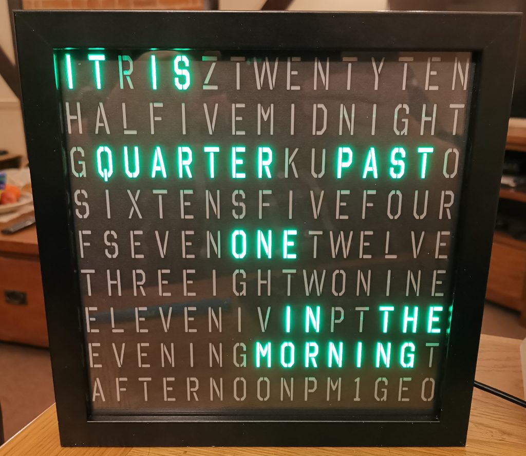
All characters are individually lit with RGB LEDs, so it is possible to scroll the time, date and temperature (or anything else) too, as the video below shows:
This project has 5 main parts:
- Case
- Character Grid & Diffuser
- LED Panel & Electronics
- Light Mesh
- Software
Lets look at these in some detail…
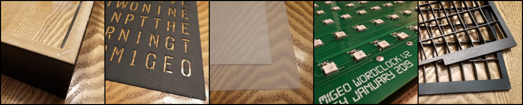
The Case – IKEA Ribba Frame
There really isn’t too much to say about the case. I used an IKEA Ribba Frame 403.784.01 which has an internal dimension of 23 x 23 cm. I removed the spacer and the hardboard backing, leaving just the glass at the front. The character grid is placed directly on the glass/perspex, followed by the diffuser sheet, followed by the light mesh and finally the PCB.
Character Grid & Diffuser
The first thing I created was the character grid with an external dimension of 230 x 230 mm to match the internal dimension IKEA Ribba Frame case. I chose the words I wanted to display carefully, planned it out, and inserted random characters in to pad out the grid where required.
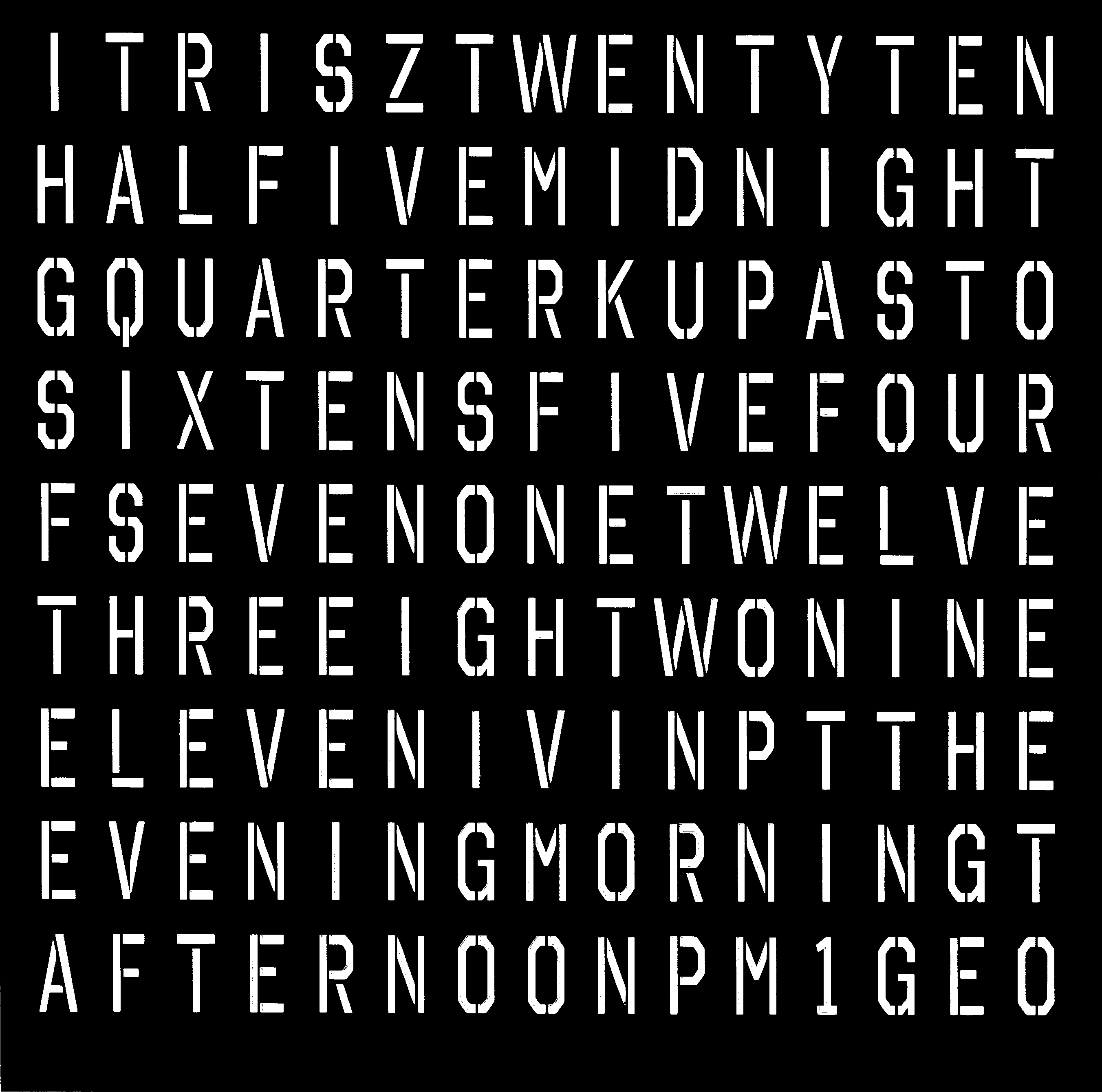
The Character Grid
I used Microsoft Excel with a stencil font (octin-stencil-free) to create the character grid below. I set the grid sizes up to match the word layout I planned to use. This resulted in 15 characters wide by 9 lines down. The 135 characters were then cut out using a laser cutter and a stencil font. You could easily use laser printing (black toner) or a vinyl cutter to achieve similar. Below is the mask I created, and the Design Files ZIP in the downloads section contains the SVG for laser cutting as well as the Excel worksheet and instructions to create your own design.
Creating your own character grid
Start by installing the octin-stencil-free font. Once you have the font installed, open the Microsoft Excel sheet up and make your changes. Do not adjust the row or column spacing as the LEDs will no longer line up with the characters. Once you have made your changes, you need to export the Excel Worksheet as a PDF, using File > Export > Create PDF/XPF.
The PDF must then be imported into your favoured drawing package. The package must be capable of working in vector graphics. I have used Corel Draw but you may use InkScape (or similar) if you wish. You must then import the PDF. The following dimensions which were suited to my setup cutting on A3 card (dimensions in mm):
PDF Position X: 294.1
PDF Position  Y: 174.1
PDF Width: 211.0
PDF Height: 204.7
Once you have imported the PDF, you will also need to create a box around it to cut the template from the sheet of card. Use the following dimensions (in mm):
Outline Position X: 294.2
Outline Position Y: 171.4
Outline Width: 230.1
Outline Height: 230.1
You will need to experiment somewhat to find the ideal conditions for your laser cutter. For the 210 gsm black card that I used, these settings were about right:
Material: Construction Paper
Thickness: 0.6 mm
Vector Cutting Power: +20% (accommodates for our old laser)
You will need to experiment if you decide to use laser printed acetate or cut vinyl or hand-cut craft card.
The Diffuser
Behind the character grid, a diffuser is used to distribute the light move evenly. I used drafting film but you could use tracing paper, or even thin copier paper. You will probably need to tinker here a little. I used the outline width and height of 230.1 mm from above to cut out the sheets for the diffuser from tracing paper using the laser cutter.
LED Panel & Electronics
Contact Me for PCB availability.
The LED panel and electronics is pretty simple. To make the design universal, each character has an LED behind it. This means that the character grid can be changed and the PCB for the LED panel can remain the same (although the software will need tweaking). An LED per character also means we can scroll text across the display, too!
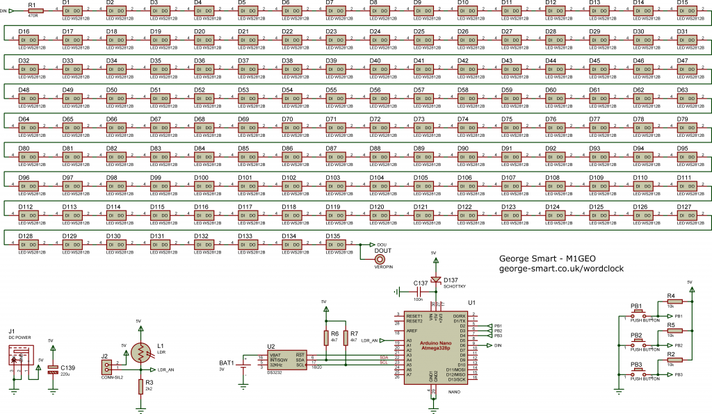
For simplicity, I have used an Arduino Nano (Atmega328P) as the main processor with a Maxim DS3232 ‘Extremely Accurate’ I²C real-time clock module with integrated crystal. The Arduino project is open source, and the compiler and programmers are easy to download, install and use. Reference code is available from GitHub, see the Downloads Section below.
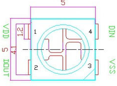
Rather than require a vast amount of logic to control the LEDs, I opted for WorldSemi WS2812B RGB LEDs often called ‘NeoPixels’. These are simple 4-pin devices, taking 5V directly and having a simple one-wire digital serial bus to control the LEDs. Each LED (or ‘pixel’) is connected in series, with data-out of one LED connecting to the data-in of the next. Since each LED contains a simple microprocessor, the datasheet suggests that each LED is decoupled by 100nF capacitor (you could probably reduce this considerably).
The LEDs will produce an impressive amount of light which is ideal in bright rooms, but at night when the ambient light is low this would be distracting. An LDR senses the light in the room and adjusts the LEDs accordingly, should this feature be required. It can be omitted if not required, or disabled in software.
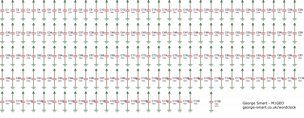
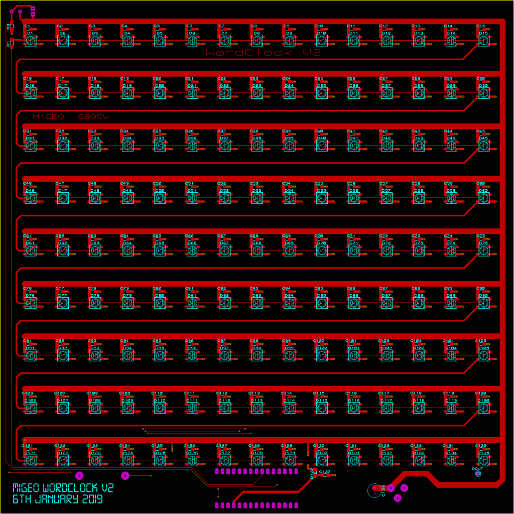
The two schematic images below show the LEDs and logic stuff, while a separate sheet just contains the decoupling capacitors. For the main LEDs, D1 through to D135, C1 though to C135 matches. There are two other 100nF decoupling capacitors: C137 decouples the MCU supply with D137 stopping the USB supply from the Arduino powering the LED, and C138 decoupling the RTC IC. Capacitor C139 is a larger electrolytic type and can be omitted. If you aren’t planning to drive the LED’s at very high brightness, you can replace D137 with a 0R resistor and power the clock through the Arduino Nano’s mini-USB. This is what I have done.
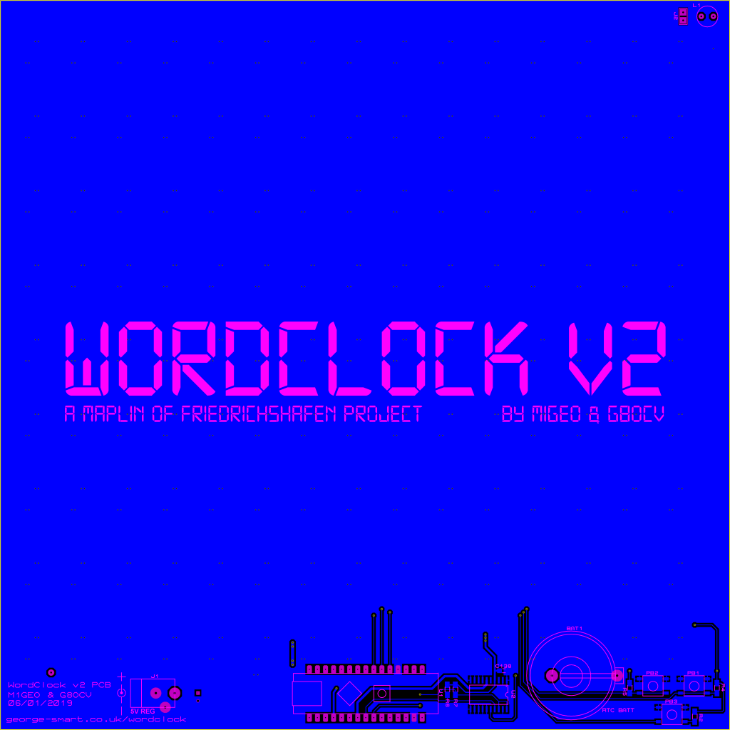
Below we see the board layout, both top side and bottom side (flipped).
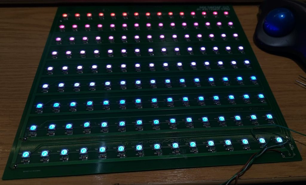
Finally, after quite a lot of soldering, the board was built. I wrote a simple pattern test for the LEDs to check that they all worked. At full brightness with all LEDs powered (255 bright, white), the display panel draws 7 Amps! When working as a clock at ‘sane’ brightness, the current draw is around 400 milli-Amps.
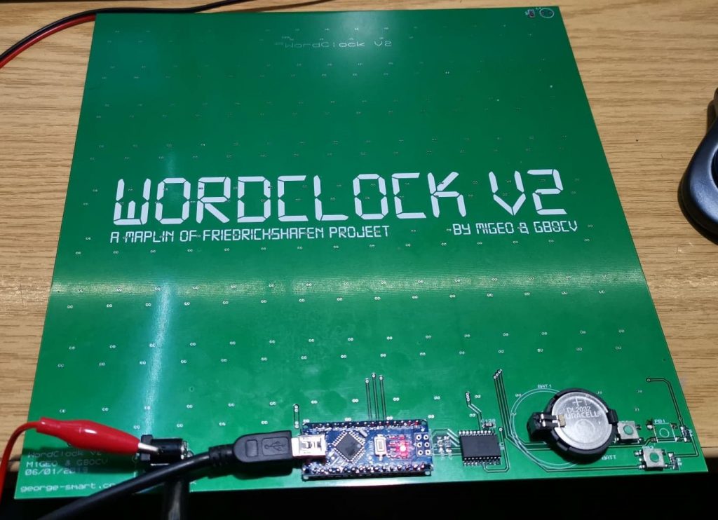
Version 2.0 and 2.1 of the boards have a couple of tiny mistakes, but nothing that stops any of the planned functionality from working. The biggest mistake is that the CR2032 battery holder silk-screen is reversed. Fortunately there is enough space to simply flip the battery holder, and you’re good to go! Version 2.1 has better positioned buttons.
PCB Bill of Materials
Item numbers with an asterisk (*) have some notes with you are referred to the build notes. I purchased all parts from AliExpress as it is cheapest option by far!
| Part | Notes | Count |
| C1-C138 | 100nF capacitor (0805) | 138 |
| C139 | 22uF capacitor | 1 |
| D1-D135 | WorldSemi WS2812B LED [4-pin devices] (5050) | 135 |
| D137* | 0 Ohm resistor (jumper) or Schottky diode (0805) | 1 |
| R1 | 470 Ohm (0805) | 1 |
| R3 | 2.2 kiloOhm (0805) [only needed with LDR] | 1 |
| R6-R7 | 4.7 kiloOhm (0805) | 2 |
| R2, R4-R5 | 10 kiloOhm (0805) [only needed with buttons] | 3 |
| PB1-PB3* | 5 mm push button [not required for clock] | 3 |
| L1* | Light dependent resistor [for auto dimming] | 1 |
| U1 | Arduino Nano | 1 |
| U2 | Maxim/Dallas DS3232 | 1 |
| BAT1* | CR2032 battery holder & CR2032 3V lithium cell | 1 |
- D137: You may power the clock through the Arduino USB socket, providing the total display current does not exceed 500 mA. With the code provided, this is fine. However, if you increase MAX_BRIGHT in the code you will need to supply more current. Diode D137 stops the USB socket from supplying high current in such a configuration. The clock is powered through the DC power jack, and D137 powers the Arduino controller.
- PB1-PB3: These 3 buttons do no function in the standard clock code.
- R2, R4-R5: These 3 resistors are only needed for the push buttons. The default clock code does not require these.
- L1: The LDR can be omitted and the set brightness value set non-zero. With the LDR fitted, the display dims as the room darkens.
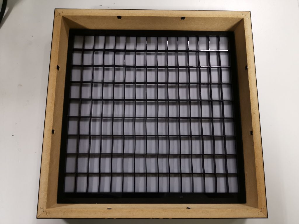
Light Mesh
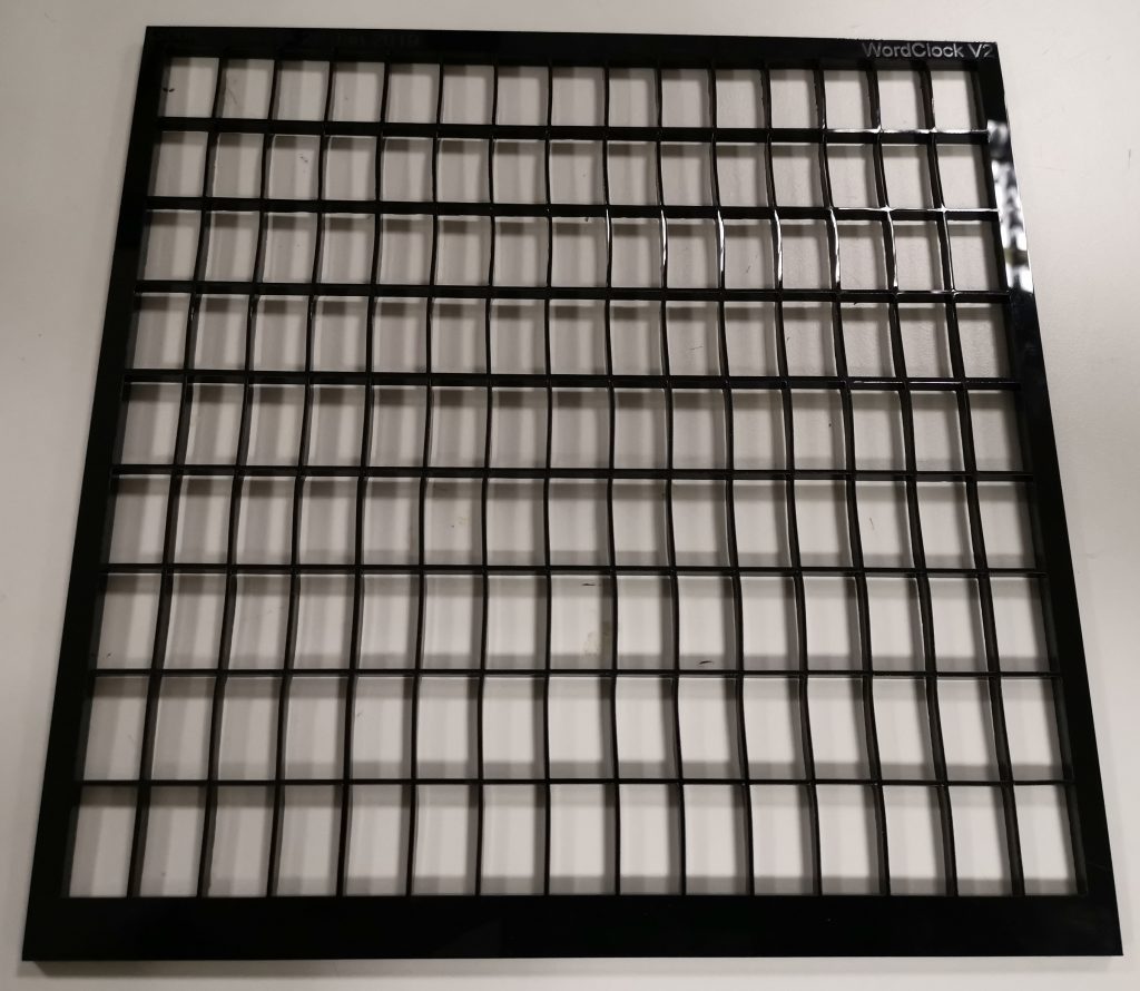
The light mesh’s purpose is to isolate each LED to each character, so that each LED only lights one character.
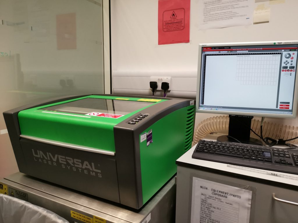
I had originally intended to 3D print this (it’s still a perfectly valid option) but I have access to a laser cutter, and this greatly reduced the build time for this stage.
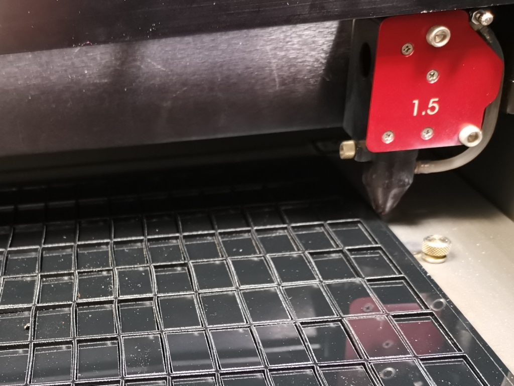
Above, the laser cutter cuts the mesh out of a 5 mm piece of black cast acrylic. Below, the finished cutout. I chose black because I figured it would minimise the chances of light creeping from one character to another. In future builds, I have used laser MDF with good results, plus it is much cheaper than acrylic. Going forward, this section would benefit from some careful design. A template to cut from a sheet of balsa wood could work very well. You’re advised to experiment a little here. There is an SVG in the Downloads Section which can be used with a laser cutter, and a PNG image in the Downloads Section which can be 3D printed at a height of around 10 mm using a 3D printer cabable of printing 230×230 mm.
Code
The firmware and software for this project can be found here: https://github.com/m1geo/WordClock
You are welcome to submit pull requests for the repository with improved features!
Firmware
The firmware the clock uses (code on the Arduino) was written by myself using commonly available modules from the Arduino community. The code is verbose, designed to be easily understood and modified.
The Adafruit NeoPixel and NeoMatrix libraries are used to drive the WS2812B LEDs. The DS3232 uses Jack Christensen’s DS3232 library to provide a hardware driver, and Paul Stoffregen’s time library. By default, the time library re-syncs to the DS3232 every 5 minutes. With a CR2032 battery the RTC will continue running when no external power is applied.
Settings are stored inside the Arduino Nano’s EEPROM, so that they are remembered through successive power cycles.
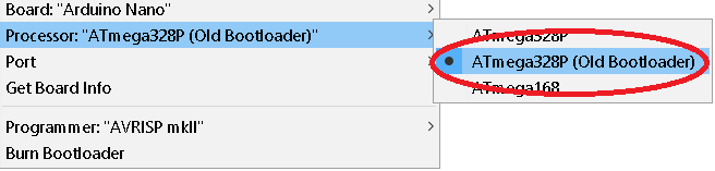
If you struggle to program the Arduino Nano, you may need to select the “Old Bootloader” version. This is common with older Arduino’s purchased from eBay, AliExpress, etc.
Software
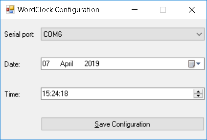
The PC software (code that runs on your computer to set the clock and clock options) was written by Robert Chipperfield M0VFC and is also included within the GitHub bundle on the releases page. You’ll need to select the serial port, and press “Save Configuration”. This will configure the clock into the default mode and set the time.
Protocol
There is a simple protocol that operates over the USB Serial cable. The first character selects the operation and then the remaining bytes are specific to the function. Leave a small delay between consecutive calls to allow the clock to process sent data.
| D | Set the time and date. | “DYYYY,MM,DD,hh,mm,ss” |
| S | Set scroll delay in ms. Smaller is faster. Typically 50-150ms. | “S75” |
| B | Set the display brightness, MIN_BRIGHT to MAX_BRIGHT. Set 0 for LDR control. | “B128” |
| U | Set the temperature units. 1=Celsius, 2=Fahrenheit, 3=Kelvin. | “U1” |
| L | L: Set month style in scroll. 0=Short month (‘Apr’), 1=Long (‘April’). | “L1” |
| P | Configure personalisation bits. 8-bit number. MSB=1 for always showing, MSB=0 for only shown on boot. 6 LSB set as required for LEDs to light. | “P159” (Decimal 159 = Binary 10011111) |
| H | Use half intervals. Offsets word display by 2.5 minutes. | “H1” |
| V | Print firmware version information | “V” |
| # | Scroll text from serial | “#This text is scrolled! :)” |
| = | Scroll the time, date and temperature. | “=” |
Downloadable Files
The files to make (and customise) the Character Grid and the Light Mesh are included in the Design Files ZIP below and the source code & released files can be found on GitHub:
- M1GEO WordClock Design Files
- Source Code (github.com/m1geo/WordClock)
- Released Versions (github.com/m1geo/WordClock/releases)
Following the publication of this project, John @ItinerantHam created a 3D printable mesh. He’s kindly given me permission to share this too:
Final Remarks
I would like to finally thank Chris G8OCV, Rob M0VFC, Dan M0WUT and Dom M0BLF for their help and advice at various points in the design of this project, as well as John 9H4G for the 3D printable mesh design.