Tag Archives: homebrew

Symmetricom GPSDO Enclosure

While tinkering with a homebrew GPSDO project, I spent a bit of time searching the depths of the internet for information and parts for my project. I found a PCB for a Symmetricom GPSDO (specifically the Symmetricom 089-03861-02 as per the PCB silkscreen in my case, although the firmware reports itself as 090-03861-03). The board was cheap because the OCXO was missing – I suspect it had aged beyond where the error voltage range was specified, making it unusable. But the board was around £15 GBP delivered from AliExpress, so I took a chance on it based on the fact it had a Furuno GT-8031F GPS receiver which is a GPS module specifically designed for timing applications which “delivers highly accurate GPS timing”. The module also had a CPU (Renesas F2317VTE25V-H8S/2317) with accompanying flash and RAM ICs as well as a Xilinx Spartan-3 FPGA (XC3S200).

Besides the missing OCXO module, my board worked perfectly. I was able to piece most of the information together from the following two resources:

I saw that some people had put their units into Hammond Manufacturing project boxes, and that gave me a few ideas. It would be nice to box the unit up with some ancillary electronics to share the UART (57600 baud, 8N1) over Ethernet TCP/IP. However, my experience of UART to Ethernet modules has always been poor and friends reported similar, so I opted for an FTDI-based USB interface (namely the FT232RL, as the cheapest/easiest part during the chip shortage of 2019-2022). I was tempted to use a Maxim MAX232 device to perform the necessary conversions, but, in the end opted for two NPN transistors – a bit hacky, but much cheaper. I may well come back to the Ethernet option in the future.

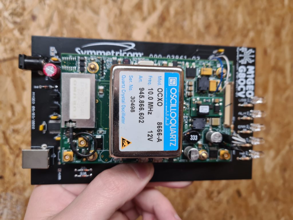
The carrier takes 5V at around 2A input on a 2.1mm x 5.5mm DC power socket, a USB-B connector and holds five LEDs: four main LEDs from the GPSDO (which are connected to test-points on the PCB, I can’t find the LED signals on any connector), plus one LED from the FTDI device showing USB activity.

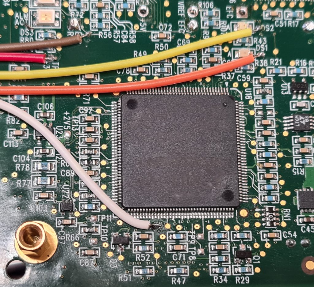
The image below shows where the LED signals are taken from. For reference, the big IC in the centre is the Xilinx Spartan FPGA:

The LED signals are all common anode, fed from +3.3V taken from the board. The LEDs are fed through a resistor, and the individual cathodes connect back to either the CPU or FPGA through another of the wires:

  • RED: +3.3V supply used to power the LED anodes
  • BROWN: Alarm
  • WHITE: Activity
  • YELLOW: Heartbeat (DS2)
  • ORANGE: Error (DS1)

There are two other LED signals (DS3 and DS4) which aren’t connected.

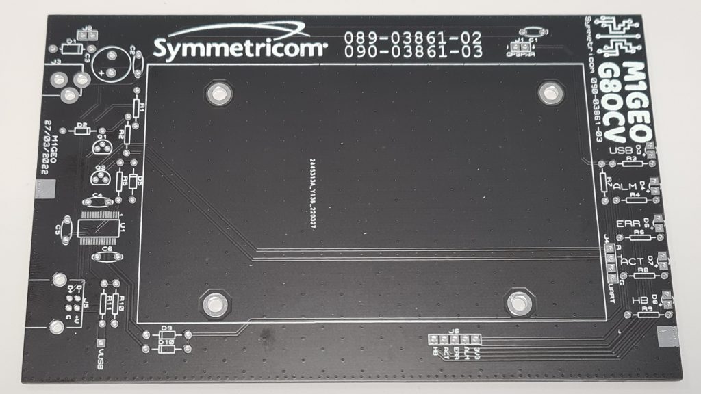
From here, I created a carrier board which had the correct mounting holes for the Symmetricom module, and offered front LEDs to show status, an easy 5V interface and a USB-UART interface to the module control port. The final board looks as below:

With the module fitted, the board looks more like the following. Note, this was an earlier version of the PCB:

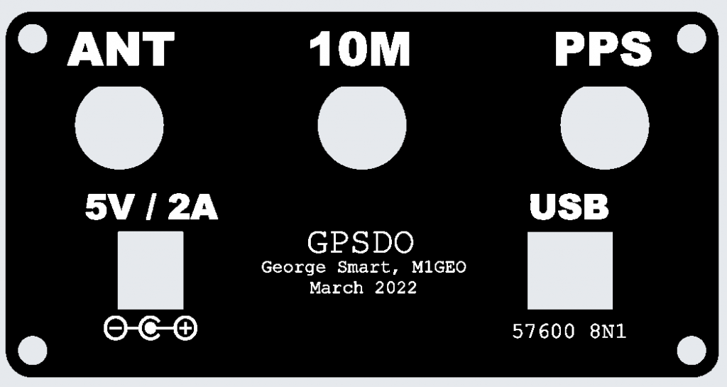
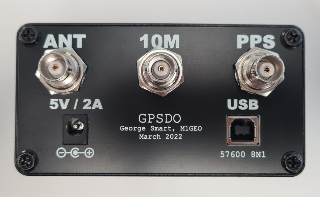
The project was designed to fit inside a Hammond Manufacturing 1455N1601BK case which takes a 160mm long by 100mm wide PCB, and the designed PCB fits the case nicely. By default, the Hammond case comes with either aluminum or plastic end plates, but I went to the effort to make PCB front and rear plates to enclose the case. Using PCB meant I was able to use tools I was familiar with to create the end places, and use the same order as the main carrier PCB. The copper on the PCB could be used to create a metal Faraday screen to enclose any electrical switching noise, and the silkscreen could be use to add legends, logos and decals.

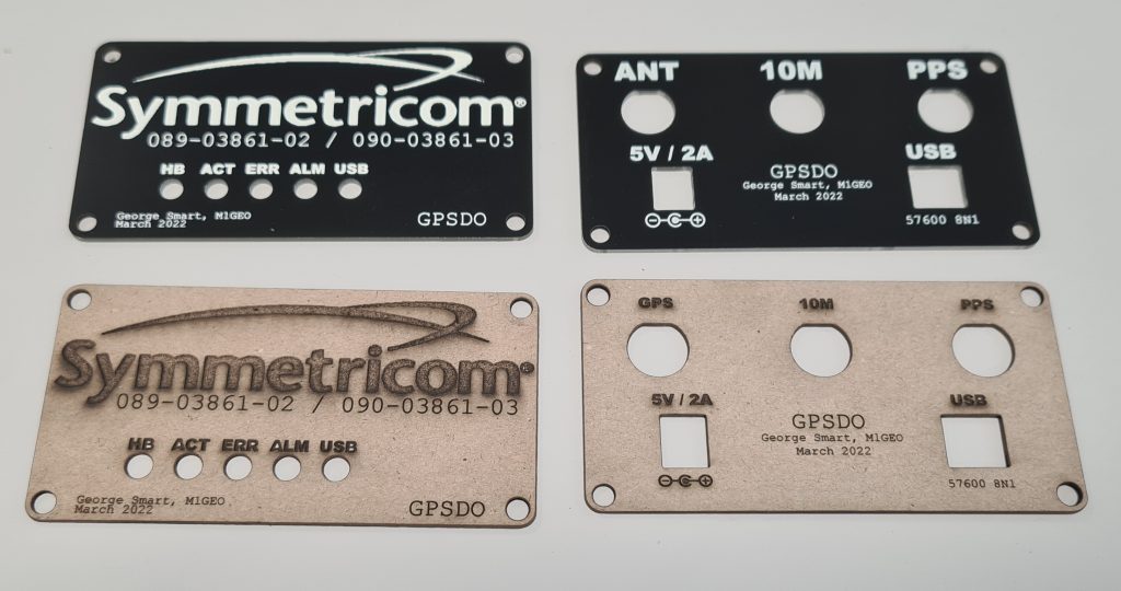
I prototyped the designs as below in the PCB package and then used my laser cutter to test them out for fit. A test fit of the front panel is shown below:

The below picture shows the PCB end boards as they arrived and the cardboard cutouts. There are some small tweaks, between the two, but overall the process worked well. One thing to note is that the internal cutouts for the BNC connectors are a little bit tight – in future I need to add an extra 0.5mm or so clearance (in addition to the 0.5mm clearance I left already). However, the connectors pushed in even if a little tightly.

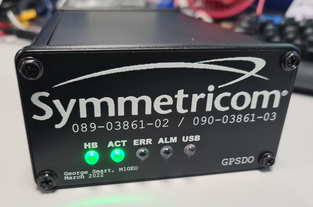
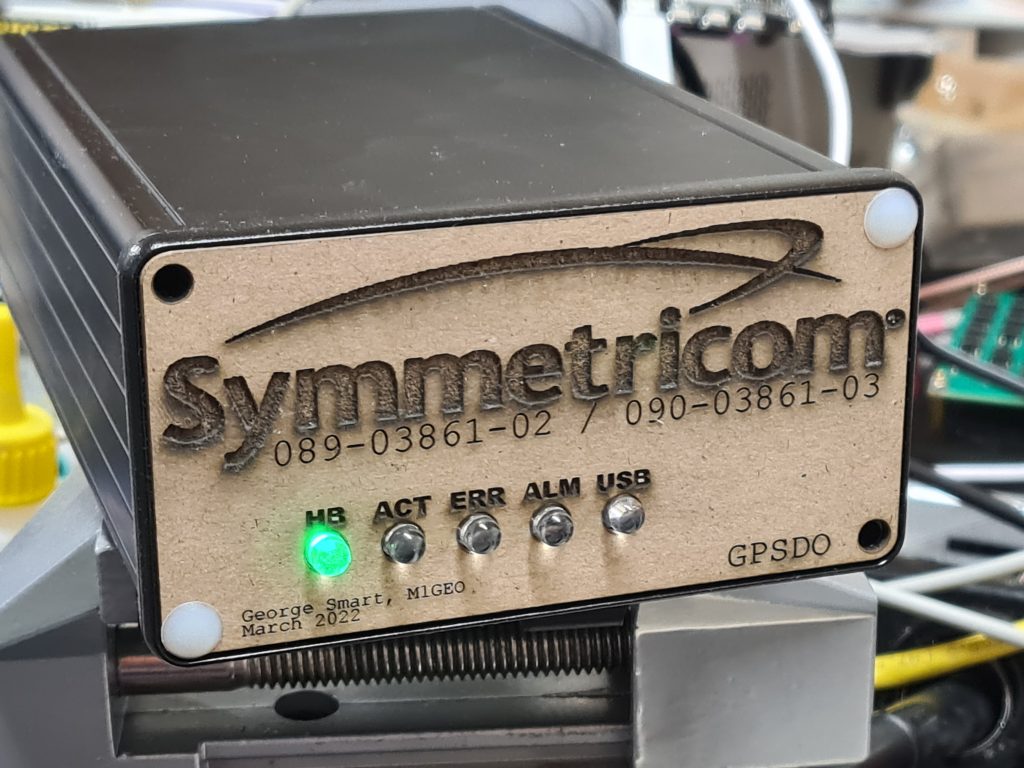
Final assembly went well, and I am very pleased with the results:

180W PA Kit Construction

This page is about the Chinese RF_PA_250_3_HV_V201 by ZGJ 2018-01-25, version 201, commonly for sale on eBay, AliExpress, etc.

Sellers, you are welcome to link to this page in your listings.

This page is a mix of information from my own investigation as well as information found online (from several sources). It is useful for those purchasing kits for such amplifiers.

Bill of Materials

ReferenceQuantityPart
C1, C2, C8, C11, C19, C20, C21, C22, C24, C25, C261110nF (103)
C3, C9, C10, C13, C15, C16, C18, C468100nF (104)
R29110KΩ
R9, R10, R11, R1245.6Ω
C5, C122680pF Mica capacitor
C471100uF 25V
C7, C1421000uF 16V
L4, L52220uH Color ring inductance 
D91Red 2.54mm LED
D1019.1V Zener diode
(use with 24V power supply)
R301560Ω 3W
(use with 24V power supply) 
R7, R82220Ω 3W Power resistance
 120Ω 3W Power resistance
RV1, RV225KΩ or 10KΩ preset pot
L1113mm NXO100 magnetism ring (2 cores)
T1113×5 NXO magnetism ring
T21Copper pipe 2pcs, 0.75 square mm wire (60cm long), 18mm NXO magnetism rings (14 cores)
Q1, Q32IRFP250
U11LM78L06 or LM78L09
Insulating spacers2 
0.8mm enameled wire1 
0.75mm high temperature cable1 

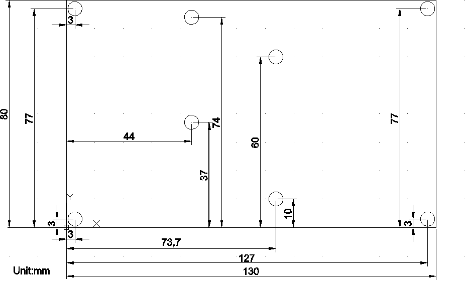
PCB Dimensions

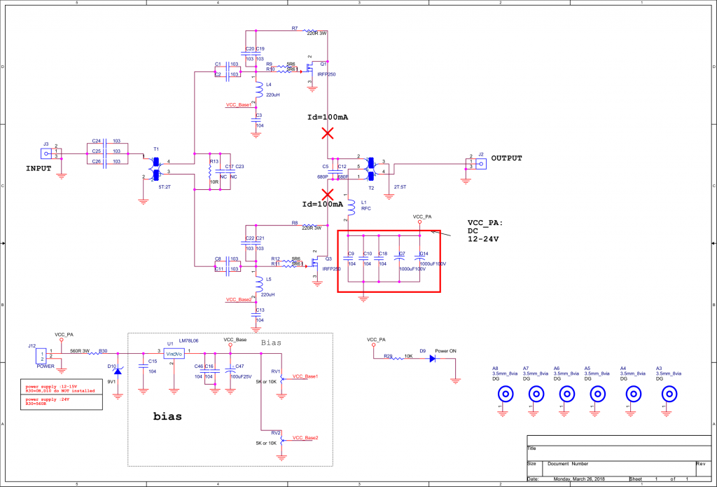
Schematic

Click image to enlarge. For transformer winding information, see below.

Build Information

Version History

  • V100 – First edition
  • V101 – Second edition: Output transformer cores reduced to 14.
  • V201 – Third edition: Power supply voltage is raised to 24V.

What you will need

  • 13.8V/24V 40A (or higher) power supply. It is better to have the function of current‐limiting protection. 6 square-mm (or more) wires for connecting the power to the amplifier board.
  • A signal source that is capable of outputting a 7 or 14 MHz signal at 10W.
  • A 50Ω dummy load rated for 200W (must be able to withstand continuous dissipation).
  • A heatsink suitable to dissipate the power of Q1 and Q3. (Recommended size: no less than 150x100x60mm).
  • A multi-meter that includes a 10A scale.
  • An oscilloscope capable of at least 20 MHz (or a spectrum analyser).

Before you start soldering

  • Wind the inductor (L1) and transformers (T1 and T2) in accordance with the information further on in this page.
  • Bend the legs on Q1 and Q3 (TO247 package) upwards, see the illustration below. Do not mount it to the top side of the board. Do not shorten the leads.
  • Tap the holes for Q1 and Q3. Screw should be M3 (3mm screw). Clean the heatsink, and remove any metal chips to avoid a short circuit.

Soldering

  • Start with smaller components first, working up towards larger components and finally plugs.
  • SMT parts can be easily soldered with an iron by adding a small amount of solder to one pad, and using tweezers to push the SMT part into the molten solder on the pad. Once cooled, add a small amount of solder to the other pads.
  • L1 and C5/C12 are not fitted at this stage.

Preparation for Powering

  • Check for any solder splashes, and poor or missing solder joints.
  • Check the DC power supply resistance to ground – no short circuits. If you have not fitted L1 yet, test from the other side of L1 pad.
(Note: in the V201 version, there are 14 cores in the output transformer, not 16 as shown here)
  • Check the LM78L06 regulator output resistance to ground – no short circuits.
  • Check the bias-set variable resistors. Rotate them as shown in the following diagram. Be careful, to rotate them to the correct end-stop. If you get this wrong, you will destroy the IRFP250N power MOSFETs. You are aiming for an initial bias voltage of 0V.
  • Mount the input transformer secondary load resistor (10Ω, 3W).
  • Solder in Q1 and Q3 and affix to the heatsink. Flow solder on the PCB trace between the MOSFET and the output transformer. This increases the current capacity of the track. See below.
  • Mount L1 as shown below.

Set bias currents

The aim of this section is to adjust the bias current to 100mA for each of the two transistors. When making adjustments, you must act slowly, and with great care – the current will do nothing for much of the adjustment range and then rise sharply. The transistors must be bolted to a heatsink during adjustment.

  • Double-check that the variable resistors are ‘zeroed’ as described above, such that when power is initially applied, there is no bias voltage present.
  • Connect a current meter in series with the positive power supply cable of the amplifier. Apply power.
  • Adjust the upper MOSFET quiescent (static) current using the upper variable resistor to cause an increase in current of 100mA (0.1A).
  • As before, now adjust the quiescent current of the lower MOSFET to further increase the current another 100mA. (A total increase of 200mA between both transistors.)
  • Solder in choke inductor L1 and mica capacitor C5/C12 if you have not already done so – the bias adjustment is complete.

Signal test

  • Connect a 50Ω dummy load to J2. The load must be capable of handling 200W.
  • Use an oscilloscope on a suitable range (or spectrum analyser with suitable attenuation) to monitor the signal at the load.
  • Connect the power supply and monitor the supply current for a moment. If the current is gradually increasing, the power must be cut immediately and check for suitable thermal connection between the power transistors Q1 and Q3 and the heatsink.
  • With the amplifier powered and no input, check the oscilloscope for signals. If there signals, immediately power off and debug the cause of self oscillation.
  • Input a small signal, gradually increasing the input signal power.
  • Observe the output waveform and the DC input current. In general, 100Vpp output across the output load corresponds to a power output of 25W into 50Ω. A load voltage of 141Vpp is 50W output, 180Vpp load voltage gives an output power of 80W, and 200Vpp at the load is a power output of 100W. Using an efficiency of 55% as an approximation, the expected DC power input can be calculated.
  • Check the temperature of the heatsink. If it is too hot to hold, then you will need to use a fan to cool the amplifier.
  • Check the output power is stable over time, and that there are no large fluctuations in output power for a fixed input power.

Finishing

  • Use a flux remover to clean any solder flux residue and tidy any poor solder joints.
  • Mount the amplifier into a box or case with suitable TX/RX switching.
  • Accompany the amplifier with a suitable low-pass filter board.

Transformer & Coil Winding

In the following diagrams process, please note:

  • To avoid scraping the enamelled wire, use needle nose pliers to smooth the edge of the ferrites. Hole edges may be sharp.
  • A “turn” on the coil is regarded as wire passing through the centre.

Winding T1

Transformer T1 primary should be 6 turns (black lines). The secondary of T1 should be 2 turns (red lines). The turns ratio is important, since if there are too many turns, the voltage on the gates of the MOSFETs will exceed the breakdown voltage and the parts will be destroyed.

Winding T2

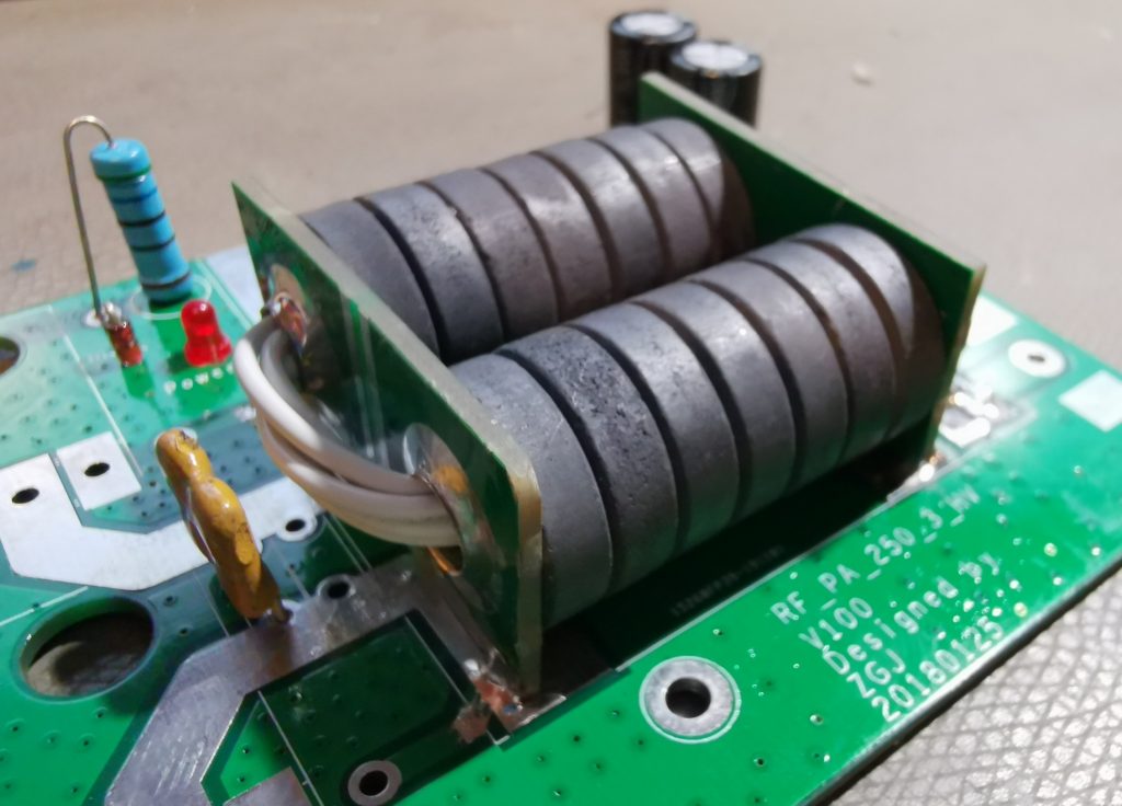
Transformer T2 primary should be 1 turn made from the two end PCBs and copper pipe. The secondary of T2 should be 5 turns of high temperature wire.

In version 201 of the kit, the number of ferrite rings is reduced from 16 to 14. You will also need 2 ferrites for winding L1 (see below).

Winding L1

L1 is a high frequency RFC choke. The 7-10 turns should be wound around two ferrite rings as used in T2. I chose 10 turns as this provides the largest choke inductance.

1kW 144MHz Amp Lives!

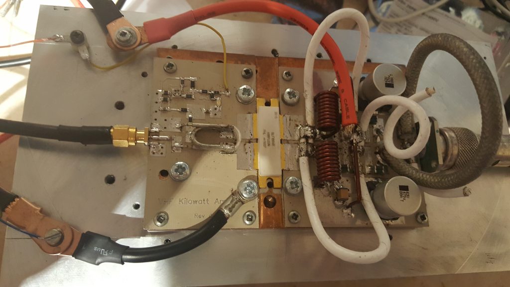
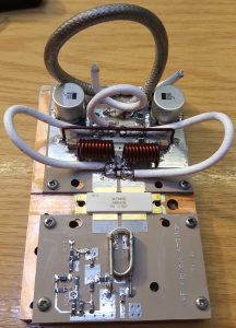
Those of you who have been following my 144 MHz 1kW amplifier project (previous posts machining heatsinks, soldering transistor down and building the pallet) will, I’m sure, be delighted to hear that I have had life out of the amplifier. In excess of 1 kW, I hasten to add!

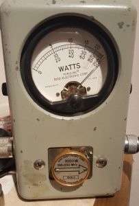
The amplifier was able to maintain in excess of 1000W for over 2 minutes.  At this point, the Bird dummy-load started to get a bit warm, so a longer test was abandoned. The amplifier pallet, however, remained cool enough to touch. As the F1JRD original design notes, the 10-Ohm coax balun does become hot (Lionel suggests around 120C at 1kW with no cooling). I, however, used a small fan running slowly to provide a gentle draft which greatly reduced the balun heat.

The next step is to add the Dallas-Maxim DS18B20 temperature sensor – the idea is to have the sensor buried into the pallet next to the transistor, to measure the copper heat spreader temperature.

BA5SBA RTL-SDR Kit

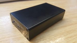
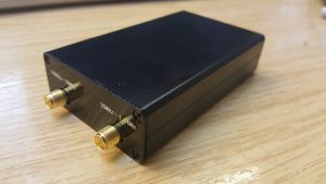
A few weeks ago I ordered a BA5SBA RTL-SDR direct sampling kit from BangGood (link here). When it arrived, I decided to put it together. The kit includes everything needed, an RTL-SDR dongle, case, PCB, enamelled wire and so on. I worked from numerous build instructions (here, here, here and here), following the clearest description of each stage.

I disassembled the original RTL-SDR dongle, removing the USB plug, IR remote receiver and Belling-Lee socket. This was easy to do. I then soldered the module into the main PCB. The SMT components were easy to solder on. I added the few remaining passives, some larger electrolytic capacitors, etc.

Two wires tack on to various voltage points to add extra smoothing, which were easy enough to connect – I used some medium thickness tinned copper wire, I guess around 0.7mm diameter. That did the trick.

Winding the two inductors was done blindly. I followed instructions to wind 8 turns around a 5mm drill; however, somewhere else said 6-9 turns around 3mm. I noticed after soldering in the coils that 300nH was the suggested inductance. In the future I will remake the coils to the correct value.

Winding the small transformer, T1, was relatively straight forward. I wound 8 turns around the ferrite core. Although I’m not entirely sure my core was ferrite. It was indistinguishable from a 2mm plastic washer. My kit had blue-red-yellow trifiliar wire in, so I followed the colour scheme in the 3rd instruction link above (page 11).

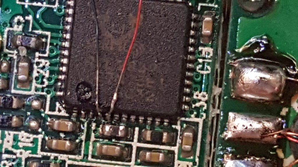
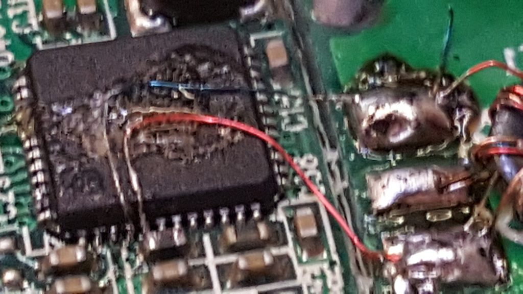
The chip has two pairs of I-Q inputs, pins 1, 2, 4 and 5. The first pair, pins 1 and 2 are connected to the E4000 front end, which mixes the higher frequency signals of VHF and UHF down to an intermediate frequency (IF). The second pair are also used in this kit to take the HF bands (on the Realtek RTL2832U, 0-24 MHz) as a second IF input. A “direct sampling” mode can be selected in the PC software to select this second input, but, there is no default wiring as this has no use inside a TV tuner dongle. By far the hardest part of this build was the soldering of hair-sized wires to the Realtek RTL2832U chip, which then go to the transformer, T1.

After a considerable struggle, these two wires were solder onto the chip. I wish I could offer some useful tips on how I did this, but I cannot – I simply struggled, and faffed around until I made the connections. I would suggest a mobile phone camera placed above the board may help, since you can use the digital zoom to see in some detail. The image above was taken as I was soldering.

Finally, I used some glue to hold the (very) fragile wires in position and soldered the other ends to the transformer. I also added a small amount of glue to the transformer, too, so as to stop it moving. It looks messy, I know, but hopefully it will add some security and stability to those otherwise poor solder connections to the Realtek chip.

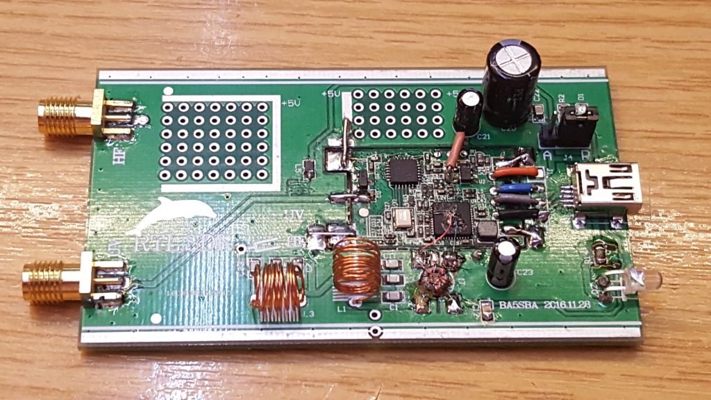
My final build looked like this:

Amazingly it also works! The image at the top shows the device inside the supplied box! Excellent!

1kW 144MHz Amp Pallet

Those of you who have been following this project evolve will have seen how I soldered the transistor to the heat-spreader and before that how I machined the heat-spreader & heat-sink after their initial use. Most recently, I have been building the new W6PQL pallet, based on the revision 4d schematic, found here.

This pallet offered several design changes compared to the original F1JRD design. The first is temperature tracked biasing for the FET. The F1JRD pallet didn’t have temperature tracking, but the W6PQL design uses a combination of 10kOhm and 22 kOhm NTC thermistors to track the temperature change of the pallet. A 6V Zener diode is used to clamp the bias supply and to also limit the maximum gate voltage the FET can see. A small 200 Ohm pot allows the bias to be adjusted to get the correct quiescent current. This is the next task.

The story continues with the initial power-up testing! First I need to commission my new General-Electric 50V/40A PSU I brought at the Rosmalen Hamfest back in early March.

Soldering Expensive Transistors

This morning, Royal Mail delivered me a parcel from Jim W6PQL all the way from California, USA. It took a couple of days to clear customs, but it arrived within about 5 days of being ordered. If you followed my previous post on this subject, about machining heatsinks, you’ll know that the last transistor I had failed on the testbench. You’ll also know that the copper heat-spreader was re-machined to suit the new PCB. This is why the heat-spreader has a few extra holes. Seeking advice from veteran microwave DXers & constructor (G4BAO, G4DDK, G8KBV, et al.) I was instructed to solder the device down. I watched a few of Jim W6PQL’s videos on soldering LDMOS parts to the copper heat-spreaders and replicated his instruction as closely as possible. You can see Jim’s instruction video here.

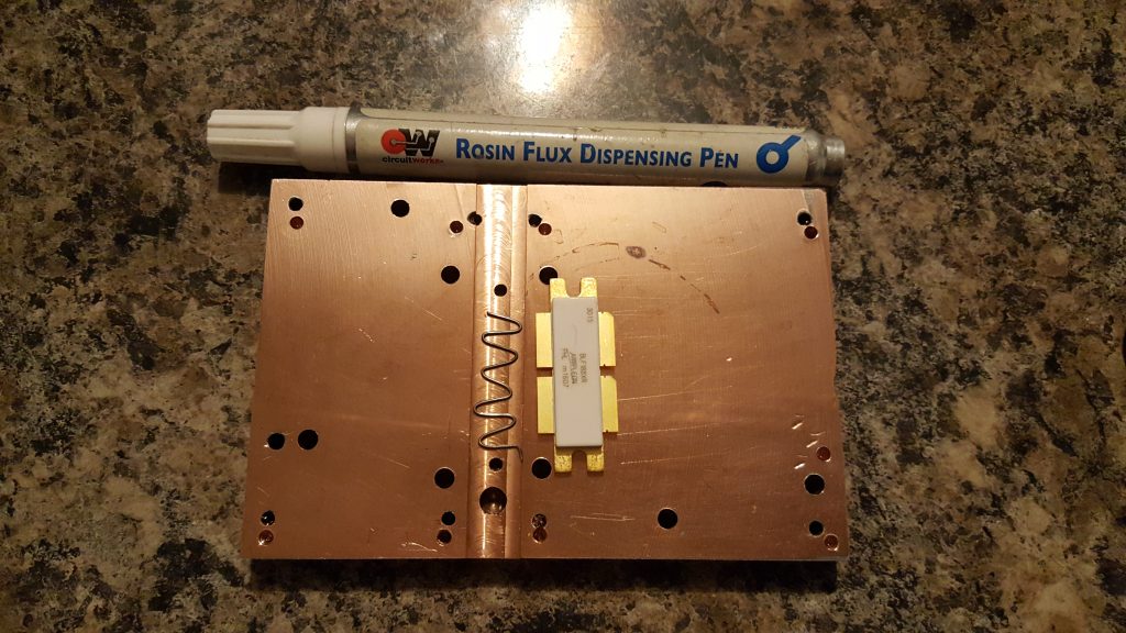
A small length of thin leaded 60/40 solder was made into a wiggle for the length of the transistor and placed in the groove previously machined in the head-spreader. I liberally applied flux to the bottom of the groove and the underside of the transistor and then sandwiched  the solder in between.

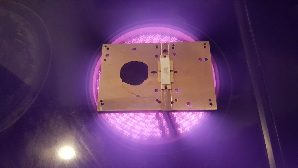
The copper heat-spreader was placed on the electric infrared hotplate and heat applied. The black dot is used to allow a laser thermometer to monitor the copper temperature. NB: this method didn’t work well.

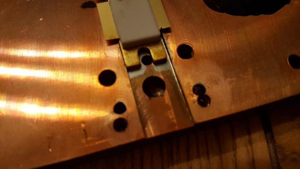
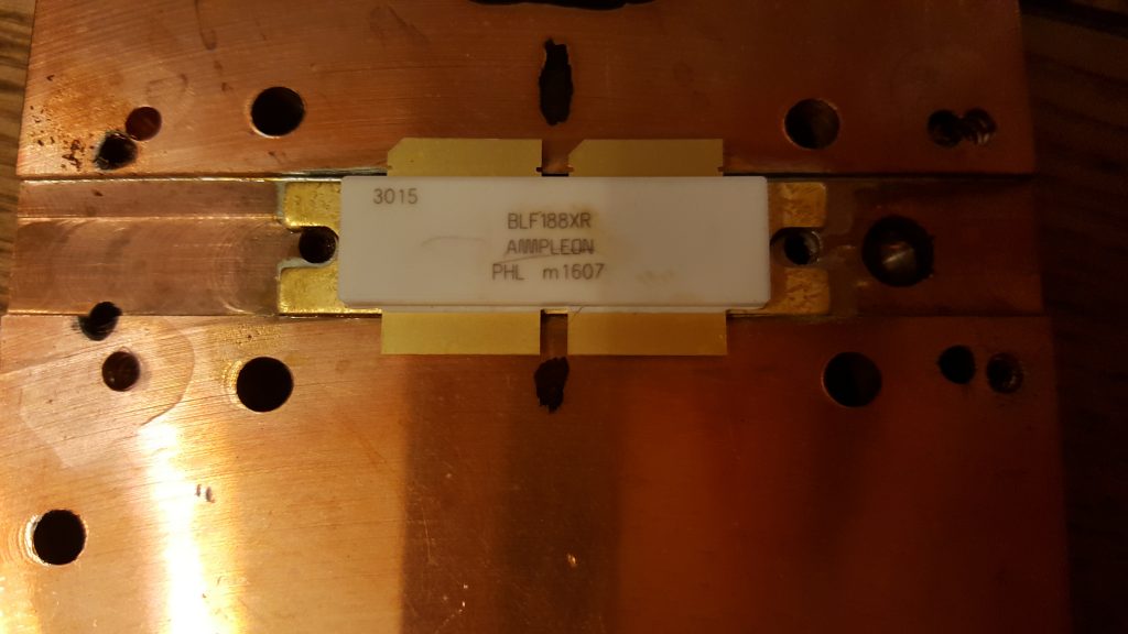
The next two images show the solder has melted and the excess squidged out the sides. It’s clear to see when the solder has melted, since the the transistor drops. It is advised to move/slide the transistor in the molten solder to remove any voids and any excess solder. I immediately killed the heat and removed the spreader from the hotplate and placed it on a heatsink. It only took a couple of minutes to cool to a temperature I could handle, and I checked the location of the transistor against the PCB mounting holes.

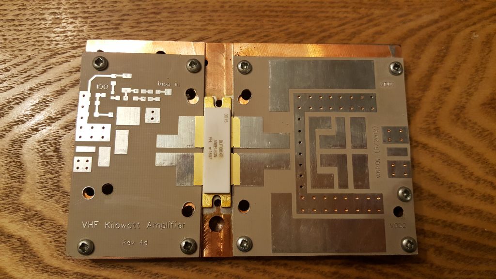
The PCBs were finally mounted as a test fit. I will populate the boards before mounting them. Unlike the original jrd1 boards, these PCBs do not need to be soldered down. This means the boards can be soldered up and then mounted.

Stay tuned for more updates…