This page details the construction of my MAX6921 VFD GPS Clock. See here for Arduino source code via GitHub.
Clock that uses TinyGPS to crack GPS strings and displays the time/date on 6 statically driven VFD tubes via 3 MAX6921s. The MAX6921 Blank line is used to dim the tubes based on an LDR reading.
The clock has the following basic features
- Set by GPS using internal hardware UART and TinyGPS.
- Temperature and Humidity readings with DHT11 sensor.
- LDR to sense ambient light and dim tubes at night using PWM via MAX6921 BLANK line.
- Pulsing decimal points as seconds indicator.
- Smooth fading on VFDs of seconds indicators and changing between numbers on display.
- Date displayed each minute (at 47 seconds).
- Open source hardware and Arduino software – hack to your needs!
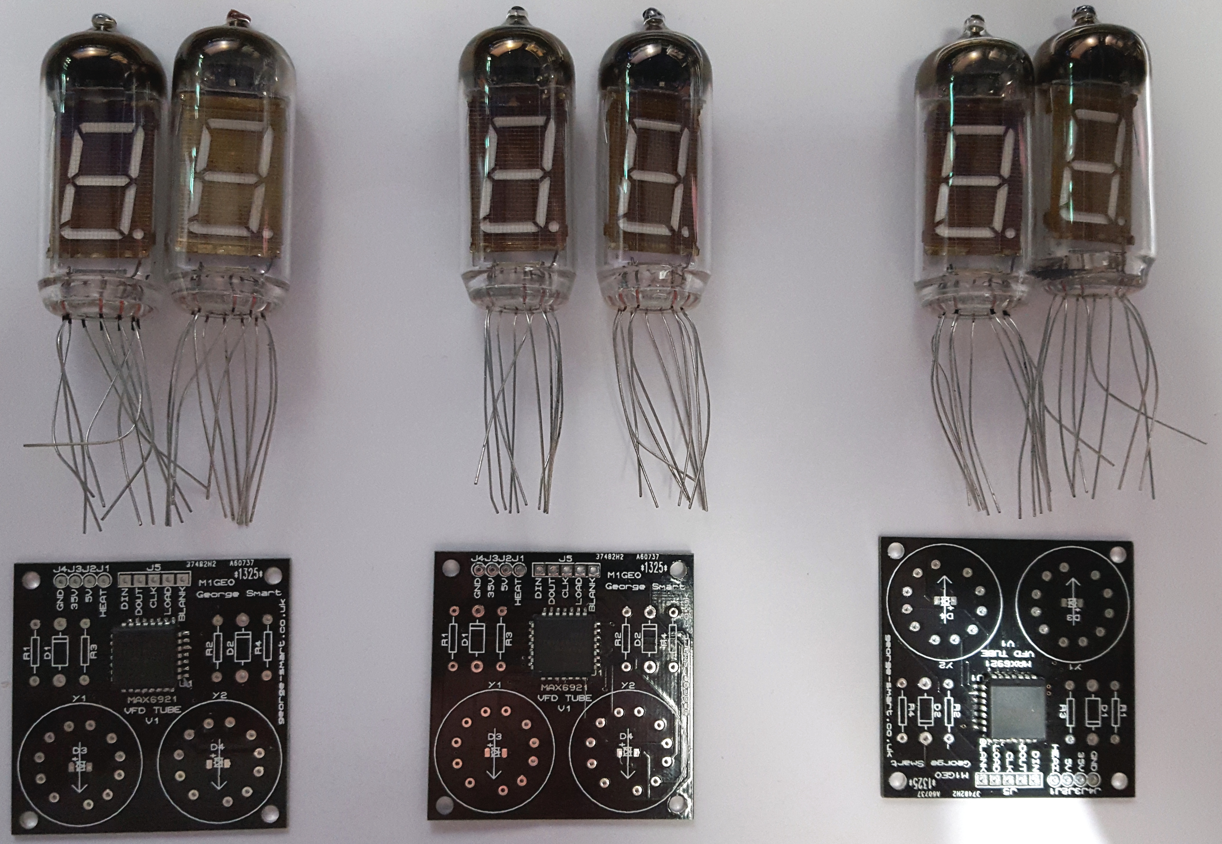
Tube Mounting Boards
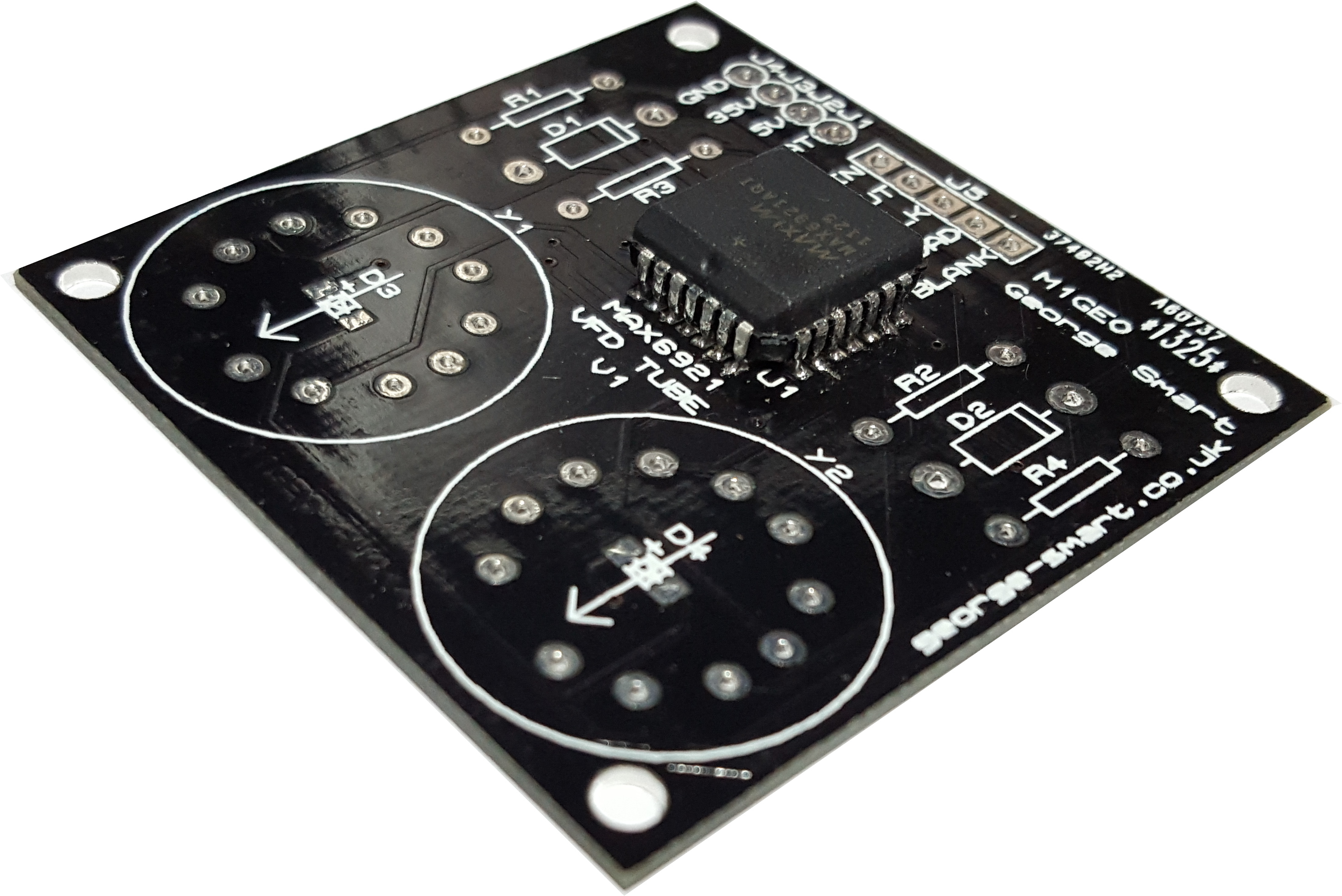
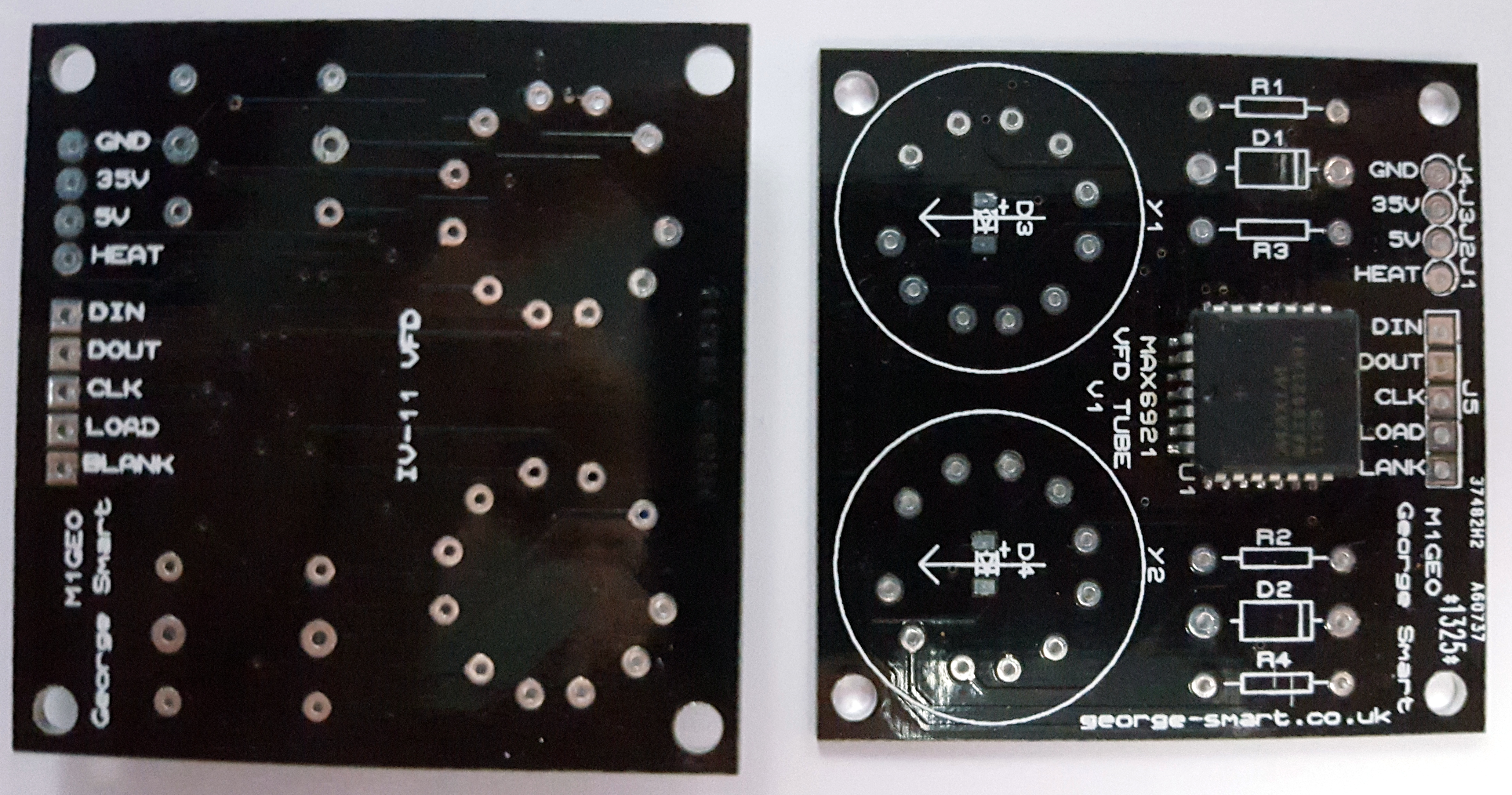
The IV-11 tubes are mounted on a small PCB available here in small quantities for cheap which also holds the MAX6921 and some of the passive components to make the tubes work. You’ll also need a +35V DC supply for the tubes (I used a cheap £1 Chinese boost converter, from 12V DC to 35V DC), a logic supply (3V to 5.5V DC), and a heater supply (I used a +5 DC supply from a 7805, which gets warm. Don’t use the Arduino 5V, as the heaters draw too much current, on these tubes, you don’t need an AC heater current).
The board will also hold 2 SMT LEDs to underlight the tube. I have used blue LEDs, but any colour will do. There are 3 other components, R1 and R2 are 27 Ohm used to set the heater current (approx 47mA, with 5V DC heater voltage), while R3 and R4 are 10 kOhm used for. D1 and D2 are 1N4148/1N4001 (or almost any other silicon diode which can handle 50mA), and allow the VFD heater to sit slightly above the 0V reference, such that the VFDs are reverse biased with 0V output from the MAX6921, causing the VFDs to be completely blanked (no leakage current) when the segments are turned off (0V).
Board Connections
The tube mounting boards have 4 power connections, and 5 data connections
Power
There are 4 power connections:
- Ground: 0V reference for all data pins and other voltages
- 35V: voltage supply for VFD tubes
- 5V: voltage supply to logic (3V to 5.5V DC)
- HEAT: heater voltage (5V with current limiting resistor R1/R2 at 27 Ohms).
Data
There are 5 data connections:
- D_IN: serial data in to the MAX6921
- D_OUT: serial data carry out from the MAX6921 (for series connecting)
- CLK: clock line to shift serial bits into MAX6921
- LOAD: load line to latch bits into buffer of MAX6921
- BLANK: blanks the VFD tube, allowing for PWM brighness control
Arduino Wiring
The 12V DC power input from the Arduino power socket. This powers the Arduino. The VIN and GND pins on the Arduino are connected to a 7805 which supplies a +5V DC rail at 1 Amp to the 6 heaters and 3 MAX6921 logic supplies, as well as the boost module, which steps the input voltage up to 35V DC for the VFD Anodes & Grid. These connect directly to the tube boards, all in parallel.
With regard to the MAX6921-to-Arduino wiring, the BLANK, LOAD, and CLK lines are tied together, in parallel, to a common pin on the Arduino. The D_IN signals are all fed separately, so all displays are updated simultaneously, allowing for greater update speed (and therefore smoother fading between changing digits). D_OUT is not used in this project. The remaining connections to the Arduino are thus:
| Pin Label | Hours Board | Minutes Board | Seconds Board |
| D_IN | 7 | 6 | 5 |
| CLK | 4 | 4 | 4 |
| LOAD | 2 | 2 | 2 |
| BLANK | 3 | 3 | 3 |
The LDR used to measure the ambient light is connected to analogue A0 on the Arduino, with a 10 kOhm resistor to the 5V DC supply. The DHT11 sensor data line connects to Arduino pin 8, if used. The GPS is fed into the Arduino hardware UART on pin 0 (“->RX”). This input must be disconnected to flash the Arduino, as the GPS string would interfere with the incoming firmware.
See [http://www.george-smart.co.uk/wiki/VFD_Clock](http://www.george-smart.co.uk/wiki/VFD_Clock) for full project information.