Tag Archives: linear amplifier

1kW 144MHz Amp Lives!

Those of you who have been following my 144 MHz 1kW amplifier project (previous posts machining heatsinks, soldering transistor down and building the pallet) will, I’m sure, be delighted to hear that I have had life out of the amplifier. In excess of 1 kW, I hasten to add!

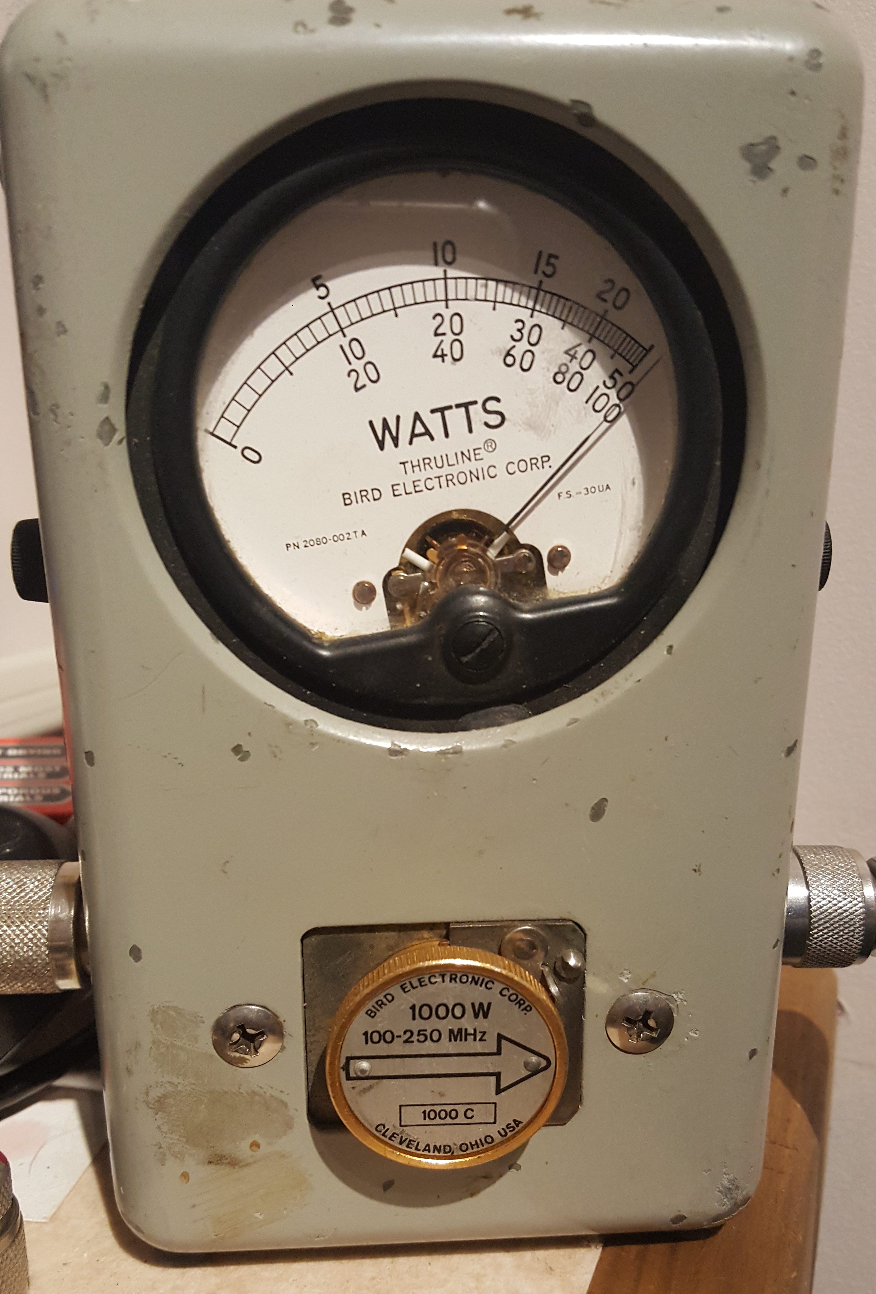
The amplifier was able to maintain in excess of 1000W for over 2 minutes.  At this point, the Bird dummy-load started to get a bit warm, so a longer test was abandoned. The amplifier pallet, however, remained cool enough to touch. As the F1JRD original design notes, the 10-Ohm coax balun does become hot (Lionel suggests around 120C at 1kW with no cooling). I, however, used a small fan running slowly to provide a gentle draft which greatly reduced the balun heat.

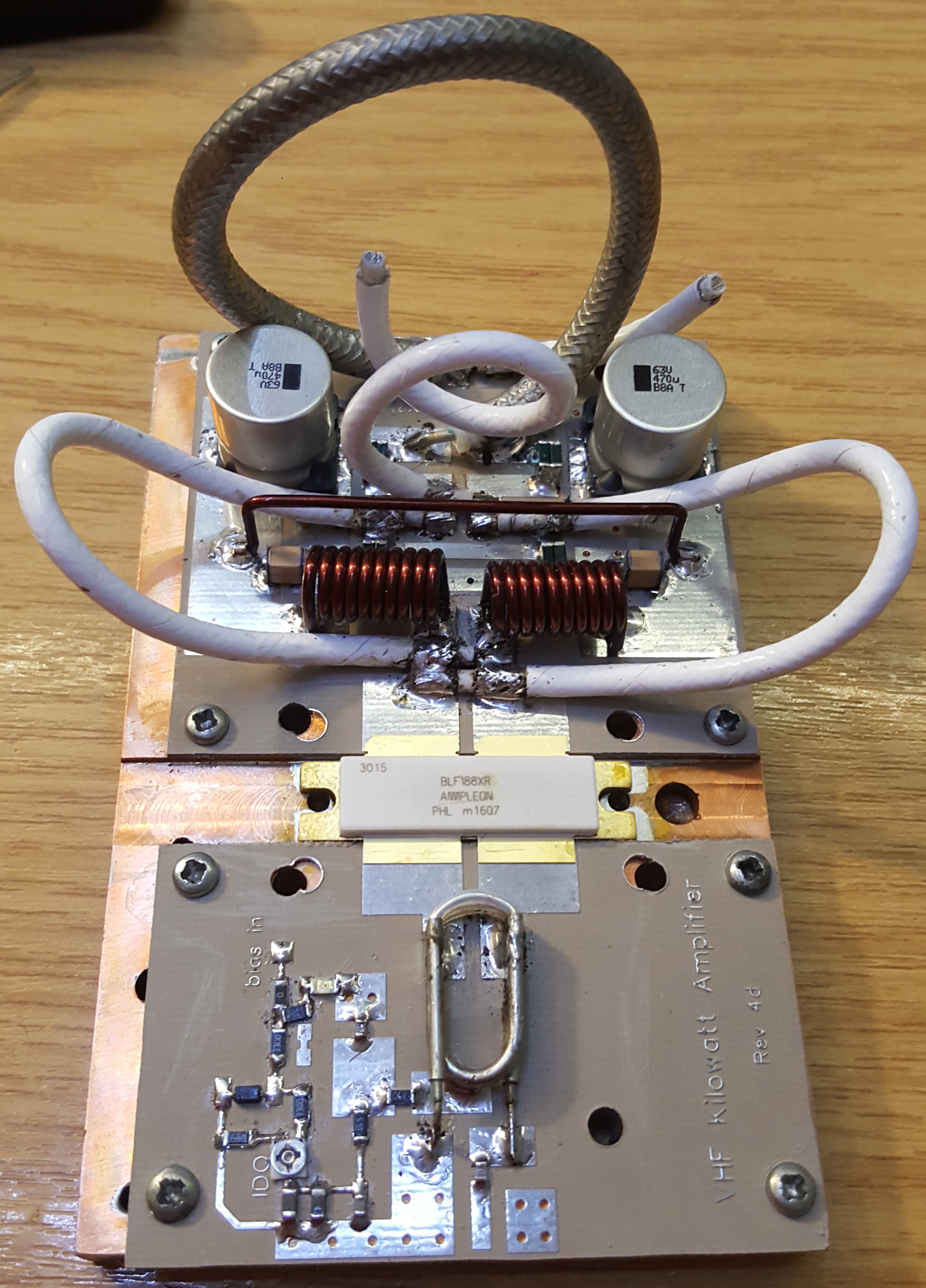
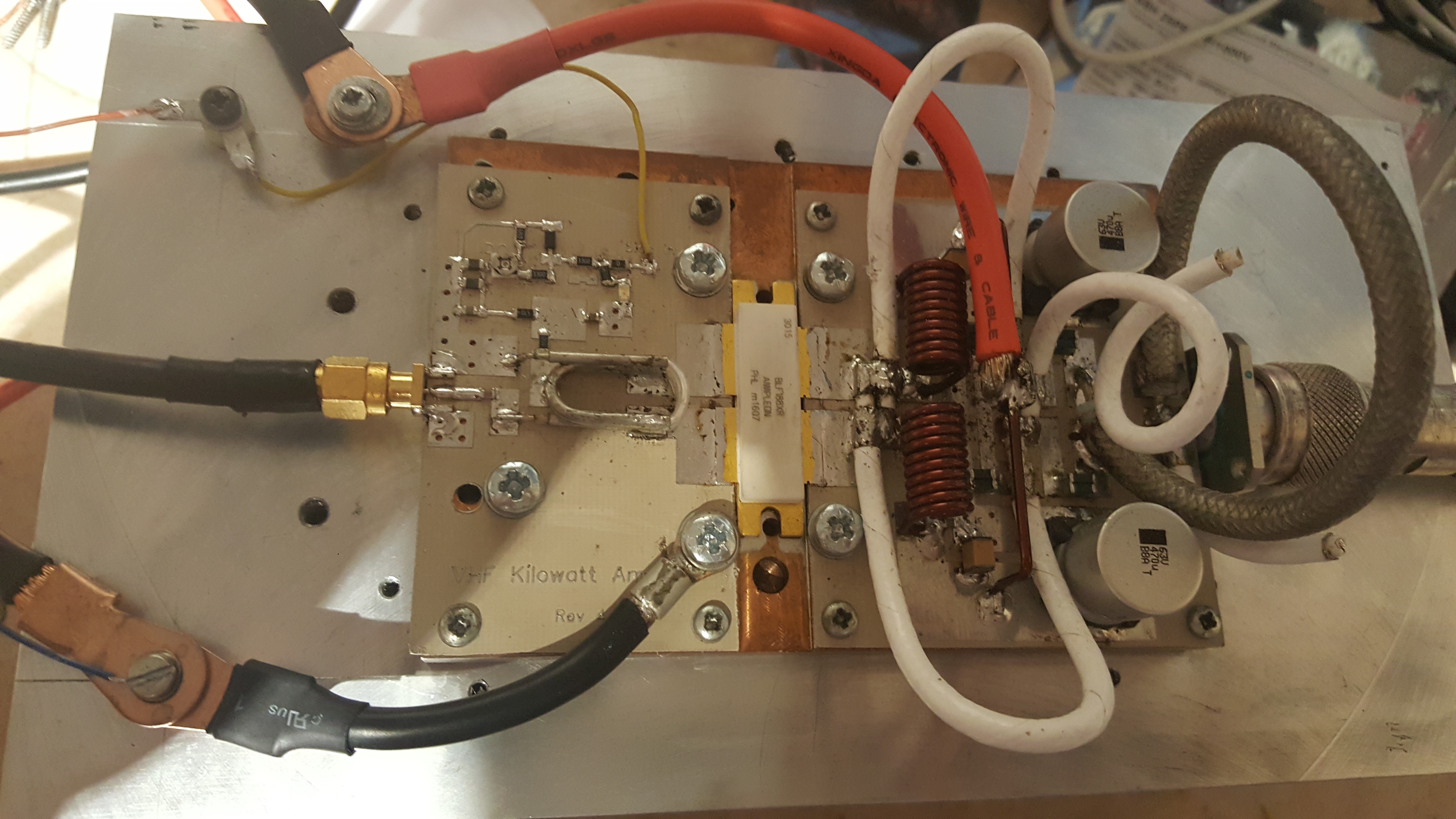
The next step is to add the Dallas-Maxim DS18B20 temperature sensor – the idea is to have the sensor buried into the pallet next to the transistor, to measure the copper heat spreader temperature.

1kW 144MHz Amp Pallet

Those of you who have been following this project evolve will have seen how I soldered the transistor to the heat-spreader and before that how I machined the heat-spreader & heat-sink after their initial use. Most recently, I have been building the new W6PQL pallet, based on the revision 4d schematic, found here.

This pallet offered several design changes compared to the original F1JRD design. The first is temperature tracked biasing for the FET. The F1JRD pallet didn’t have temperature tracking, but the W6PQL design uses a combination of 10kOhm and 22 kOhm NTC thermistors to track the temperature change of the pallet. A 6V Zener diode is used to clamp the bias supply and to also limit the maximum gate voltage the FET can see. A small 200 Ohm pot allows the bias to be adjusted to get the correct quiescent current. This is the next task.

The story continues with the initial power-up testing! First I need to commission my new General-Electric 50V/40A PSU I brought at the Rosmalen Hamfest back in early March.

BNOS LPM144-10-100 Repair

I have had a B.N.O.S LPM144-10-100 solid state linear amplifier for some time. It brought it at a ham fest and it worked fine. However, when I tried to use it recently, I noticed that sometimes the amplifier would work, but other times there was no output. Due to the intermittent nature of the fault, I knew it couldn’t be the main power transistor (MRF247). The most likely cause was one of the 3 relays. There were also 5 electrolytic capacitors. I decided to change all 8 parts.

The first thing I did was cross correlate what I had with the circuit diagram (click for full size image/download).

The PCB 

Using a desoldering station to melt and vacuum extract the solder, the 3 relays are easily removed from the PCB with no board damage.

Closeup of the 3 removed relays:

Comparing the original PCB photo with the one below, you can see the 3 replacement relays and 5 capacitors.

I used a Finder 12V miniature DPDT 8A relay as my replacements sourced from Rapid Electronics in the UK, but these relays are universally available from different manufacturers. You will need a DPDT relay with 12V coil (not SPDT as this article previously stated [thanks to Keith GM4YXI for spotting this issue]). My current suggestion would be the TE Connectivity / Schrack RT424012 (datasheet).

Below is the amplifier working! Yay!