
Please note that this page is still a work in progress.
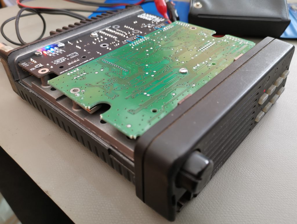
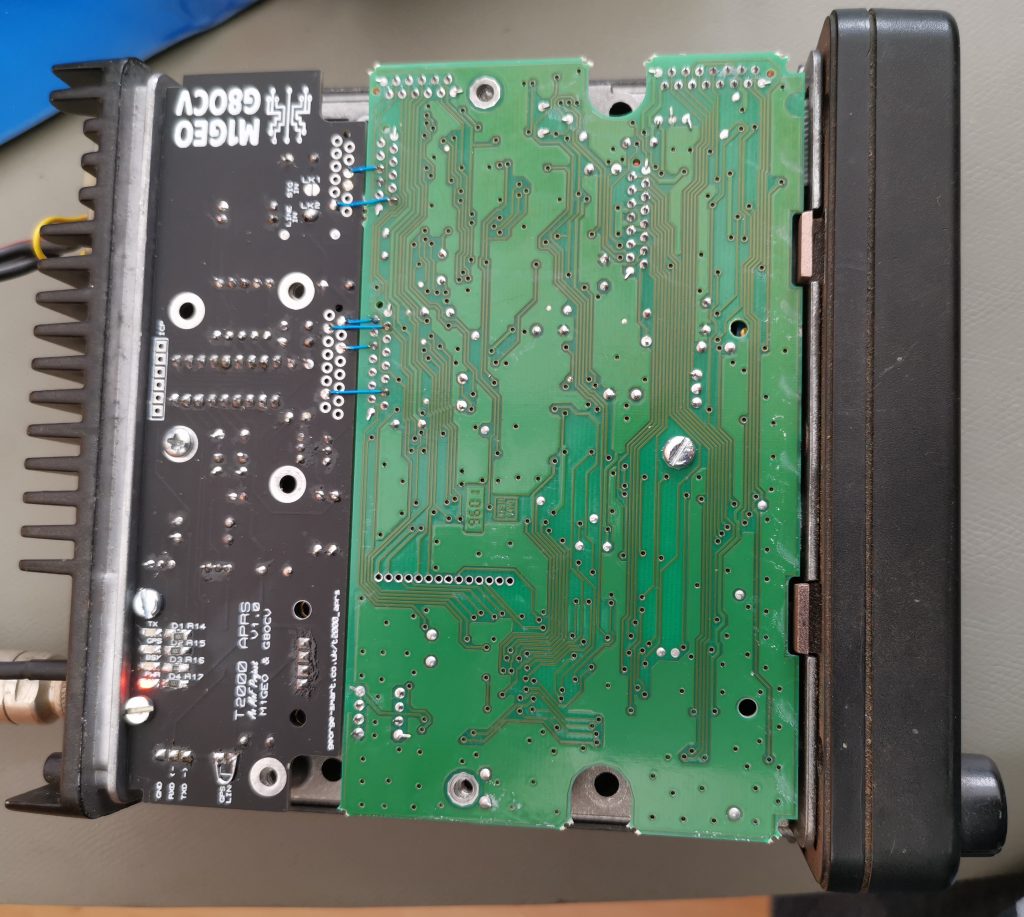
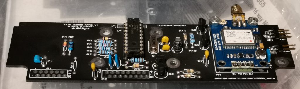
This project is designed to be a PCB that will fit inside the Tait T2000 radio as an option board to add APRS capabilities to the radio. The modification is as easy as removing the top cover, plugging in the two board connectors, fitting 3 screws and replacing the cover. The APRS board fits with the standard radio connectors just as you’d expect of a genuine Tait module.
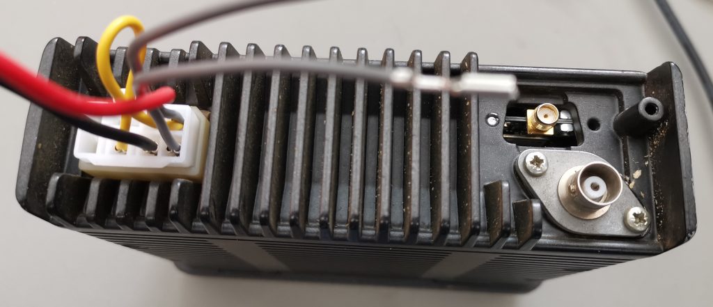
The GPS antenna is connected to an SMA antenna which is visible through the D-sub socket hole in the back case.
If programmed for momentary action inside the Tait software, the ‘AUX’ button on the front panel will cause a location packet to be transmitted.
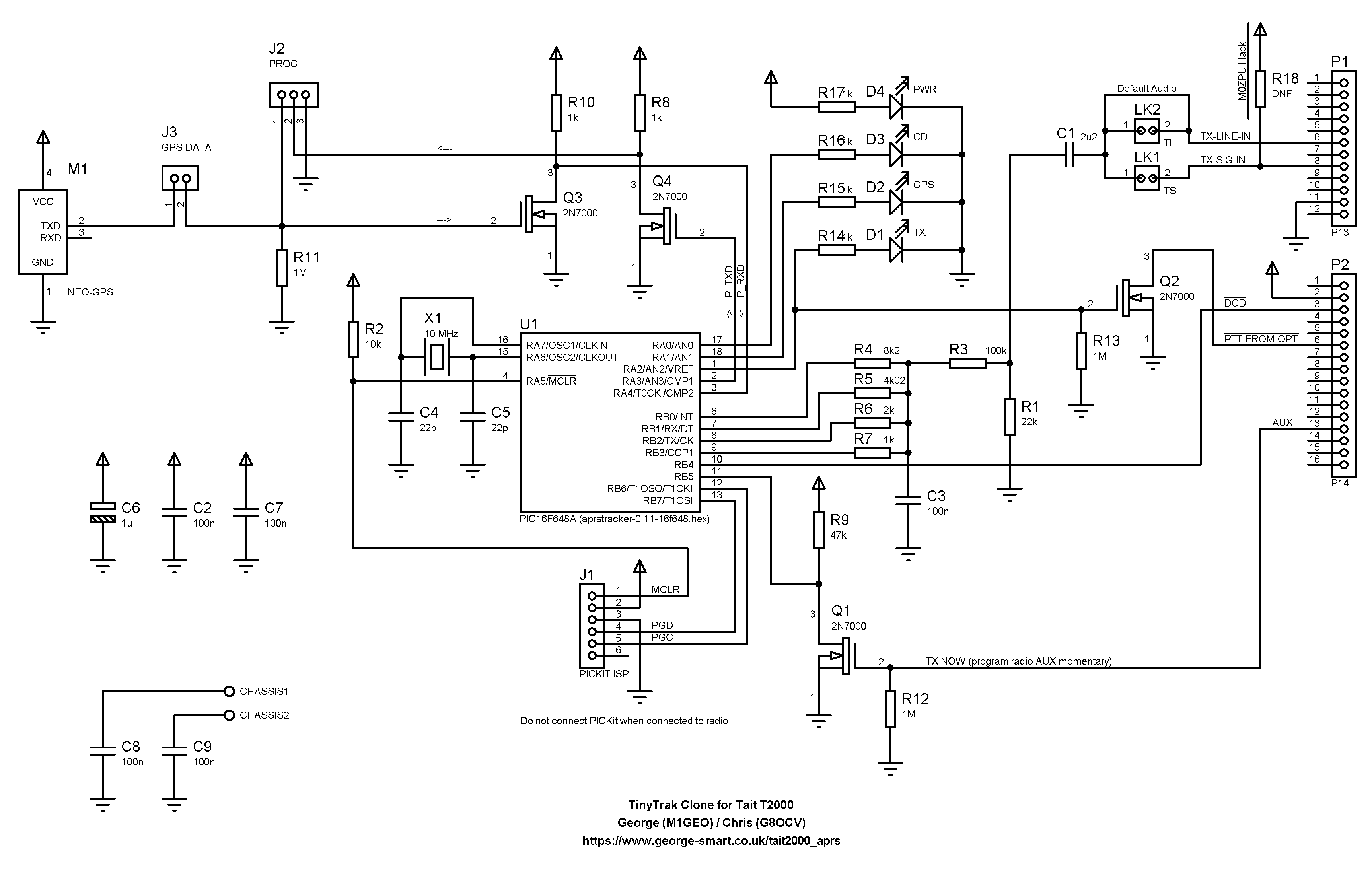
Schematic
Build Notes
- Do not fit R18.
- Be careful crimping the plugs P1a and P2a on to the ribbon, as they have a protruding pin.
Bill of Materials
Please note that this section is still at work in progress. Although the components are correct and the project will work with the following part codes, the component series’ are mixed, and the aesthetic of the board will be slightly inferior.
| Category | Quantity | Order Code | Value |
| M1 | 1 | eBay | NEO GPS Module (NEO-6M, NEO-7M) |
| C1 | 1 | RS 841-0758 | 2u2 |
| C2-C3, C7-C9 | 5 | RS 538-1310 | 100n |
| C4-C5 | 2 | RS 852-3324 | 22p |
| C6 | 1 | RS 475-9009 | 1u |
| R1 | 1 | RS 135-954 | 22kΩ |
| R2 | 1 | RS 125-1153 | 10kΩ |
| R3 | 1 | RS 135-982 | 100kΩ |
| R4 | 1 | RS 683-4082 | 8.2kΩ (used in DAC) |
| R5 | 1 | RS 477-8117 | 4.02kΩ (used in DAC) |
| R6 | 1 | RS 683-3430 | 2kΩ (used in DAC) |
| R7 | 1 | RS 683-3165 | 1kΩ ( used in DAC) |
| R8, R10 | 2 | RS 125-1150 | 1kΩ |
| R14-R17 | 4 | RS 901-3682 | 1kΩ – SMT 0805 (for LEDS, D1-D4) |
| R9 | 1 | RS 135-976 | 47kΩ |
| R11-R13 | 3 | RS 136-058 | 1MΩ |
| R18 | 1 | DNF | Reserved for special use (do not fit) |
| U1 | 1 | RS 623-0320 | PIC16F648A (Firmware: aprstracker-0.12-16f648.hex, see below) |
| Q1-Q4 | 4 | RS 739-0224 | 2N7000 |
| D1 | 1 | RS 497-4804 | Red LED (TX) – SMT 0805 (optional) |
| D2 | 1 | RS 691-0442 | Blue LED (GPS) – SMT 0805 (optional, recommended) |
| D3 | 1 | RS 700-7904 | Orange LED (CD) – SMT 0805 (optional) |
| D4 | 1 | RS 694-2786 | Green LED (PWR) – SMT 0805 (optional) |
| J1 | 1 | RS 681-2492 | 6-pin SIL 0.1″ vertical pins (PICKIT ISP) |
| J2 | 1 | RS 360-6437 | 3-pin SIL 0.1″ right angle pins (PROG) |
| J3 | 1 | Share J2 | 2-pin SIL 0.1″ right angle pins (GPS DATA Jumper) |
| P1 | 1 | RS 301-8054 | Micro-MaTcH 12-pin PCB Mount (P13) |
| P1a | 2 | RS 680-4993 | Micro-MaTcH 12-pin Ribbon Mount |
| P2 | 1 | RS 745-5365 | Micro-MaTcH 16-pin PCB Mount (P14) |
| P2a | 2 | RS 680-4990 | Micro-MaTcH 16-pin Ribbon Mount |
| X1 | 1 | RS 852-4860 | 10 MHz crystal |
| MISC | 1 | RS 289-9874 | 16-way ribbon cable for P1/P2 |
Programming the Board
Programming the PIC microcontroller
Use a PIC programmer to program the board externally, or an in-circuit programmer, such as the Mircochip PICKit, attached to J1. The board should be programmed before connecting to the radio, since programming voltages may damage the radio and cause problems programming.
The aprstracker firmware version 0.12 (supporting 9600 baud GPS) by PE1ICQ and PE1RXQ can be downloaded here: aprstracker-0.12.tar.gz.
Programming the tracker information
The tracker can be programmed with any program compatible with the PE1ICQ and PE1RXQ software. The aprstracker-0.12 software includes a Linux program to configure the tracker, which in a terminal looks like below:
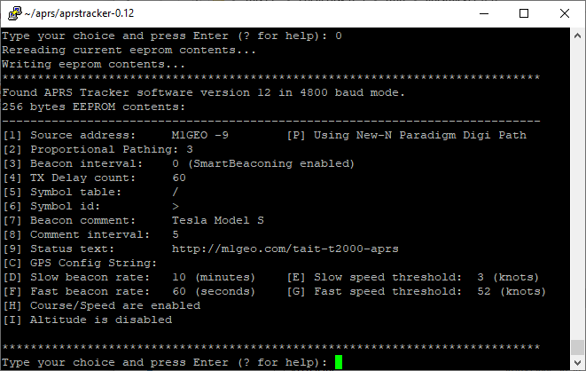
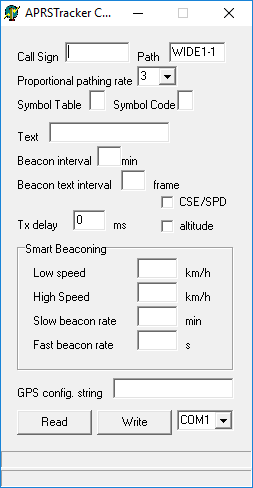
The APRSTracker Configure software by Jedrzej SQ2DK, which can be downloaded from here, and allows for easy programming via Windows. I have found the Linux software to give better results on a new device. Set “Beacon interval” to 0 to enable smart beaconing.
Programming is done with an FTDI USB-TTL-Serial interface connected to J2. This can be done when the board is connected into the radio and powered. To program, J3 (GPS link) must be removed, as it uses the same UART (data input on the PIC) for programming and GPS input.
To run the tracker J3 must be linked. The GPS LED will flicker with GPS frames.
Known Issues
GPS Data Corrupts Configuration
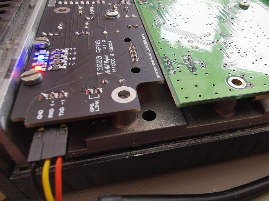
With time, I have found that the GPS data-stream can corrupt the EEPROM configuration. Essentially, the GPS starts outputting data before the PIC is out of reset, which means the PIC starts listening to the UART stream in the middle of a GPS sentence, interpreting the first few characters received as control characters – occasionally, these are valid instructions and the PIC randomly overwrites some of it’s configuration as if instructed to by the PC software.
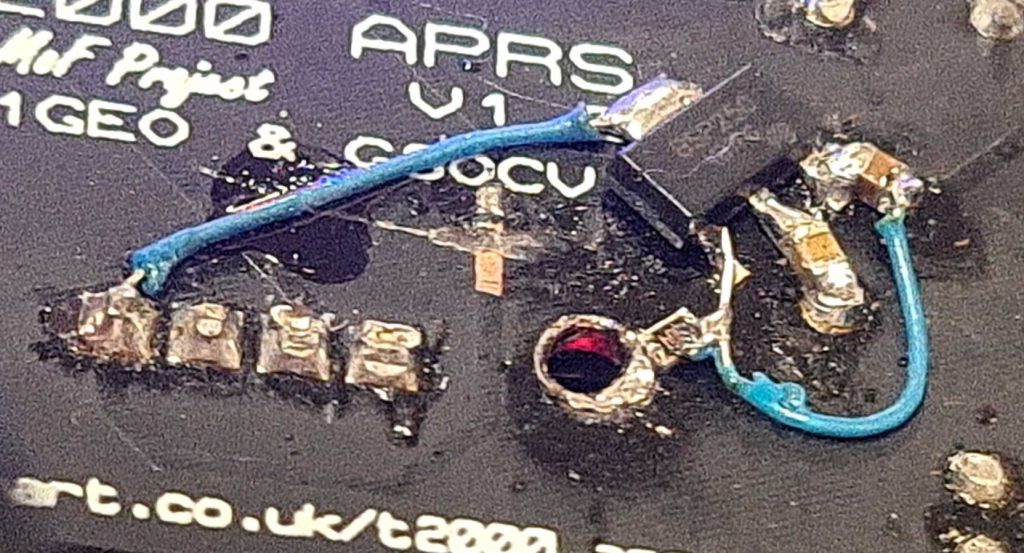
This is easily fixed by adding a delay to the GPS power up. In my initial testing and board bring up, I added a BSP250 P-channel MOSFET with an RC time constant circuit set to 2 seconds. This ensures the PIC is operational before the GPS is powered. The picture below shows a hacked together test.
Future boards will incorporate a similar fix.