
A few weeks ago I ordered a BA5SBA RTL-SDR direct sampling kit from BangGood (link here). When it arrived, I decided to put it together. The kit includes everything needed, an RTL-SDR dongle, case, PCB, enamelled wire and so on. I worked from numerous build instructions (here, here, here and here), following the clearest description of each stage.
 |
 |
I disassembled the original RTL-SDR dongle, removing the USB plug, IR remote receiver and Belling-Lee socket. This was easy to do. I then soldered the module into the main PCB. The SMT components were easy to solder on. I added the few remaining passives, some larger electrolytic capacitors, etc.
Two wires tack on to various voltage points to add extra smoothing, which were easy enough to connect – I used some medium thickness tinned copper wire, I guess around 0.7mm diameter. That did the trick.
Winding the two inductors was done blindly. I followed instructions to wind 8 turns around a 5mm drill; however, somewhere else said 6-9 turns around 3mm. I noticed after soldering in the coils that 300nH was the suggested inductance. In the future I will remake the coils to the correct value.
Winding the small transformer, T1, was relatively straight forward. I wound 8 turns around the ferrite core. Although I’m not entirely sure my core was ferrite. It was indistinguishable from a 2mm plastic washer. My kit had blue-red-yellow trifiliar wire in, so I followed the colour scheme in the 3rd instruction link above (page 11).
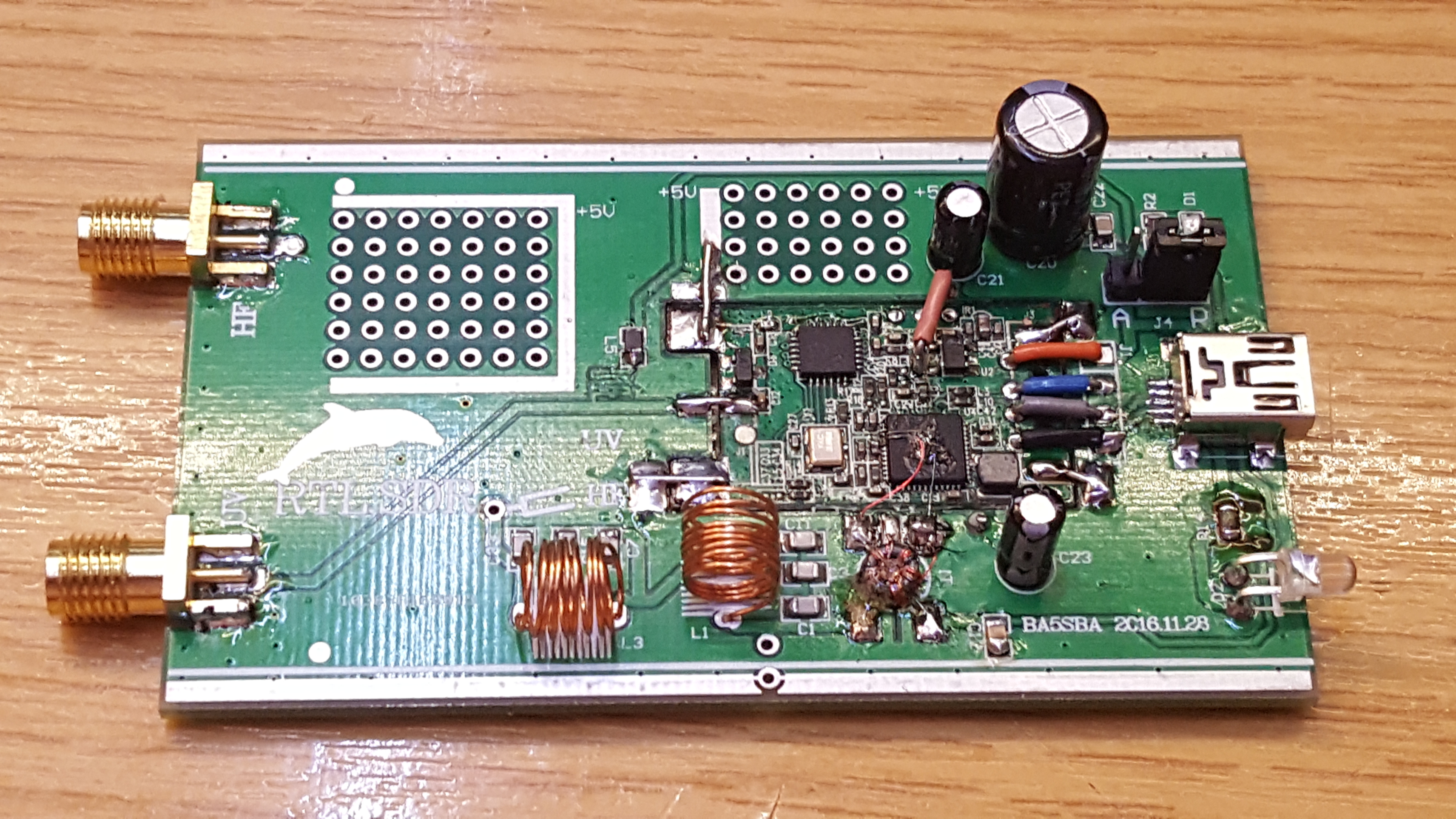
The chip has two pairs of I-Q inputs, pins 1, 2, 4 and 5. The first pair, pins 1 and 2 are connected to the E4000 front end, which mixes the higher frequency signals of VHF and UHF down to an intermediate frequency (IF). The second pair are also used in this kit to take the HF bands (on the Realtek RTL2832U, 0-24 MHz) as a second IF input. A “direct sampling” mode can be selected in the PC software to select this second input, but, there is no default wiring as this has no use inside a TV tuner dongle. By far the hardest part of this build was the soldering of hair-sized wires to the Realtek RTL2832U chip, which then go to the transformer, T1.
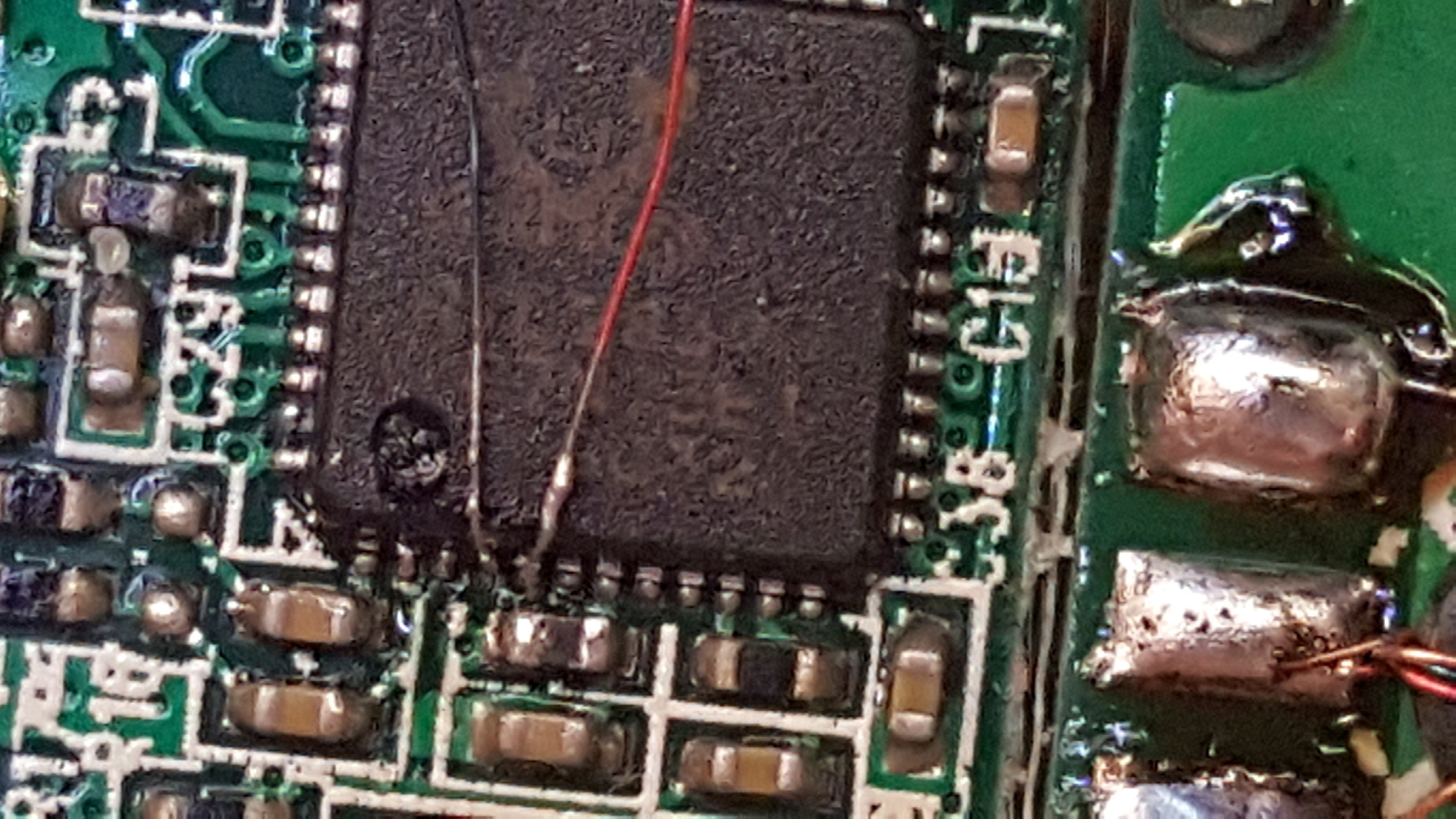
After a considerable struggle, these two wires were solder onto the chip. I wish I could offer some useful tips on how I did this, but I cannot – I simply struggled, and faffed around until I made the connections. I would suggest a mobile phone camera placed above the board may help, since you can use the digital zoom to see in some detail. The image above was taken as I was soldering.
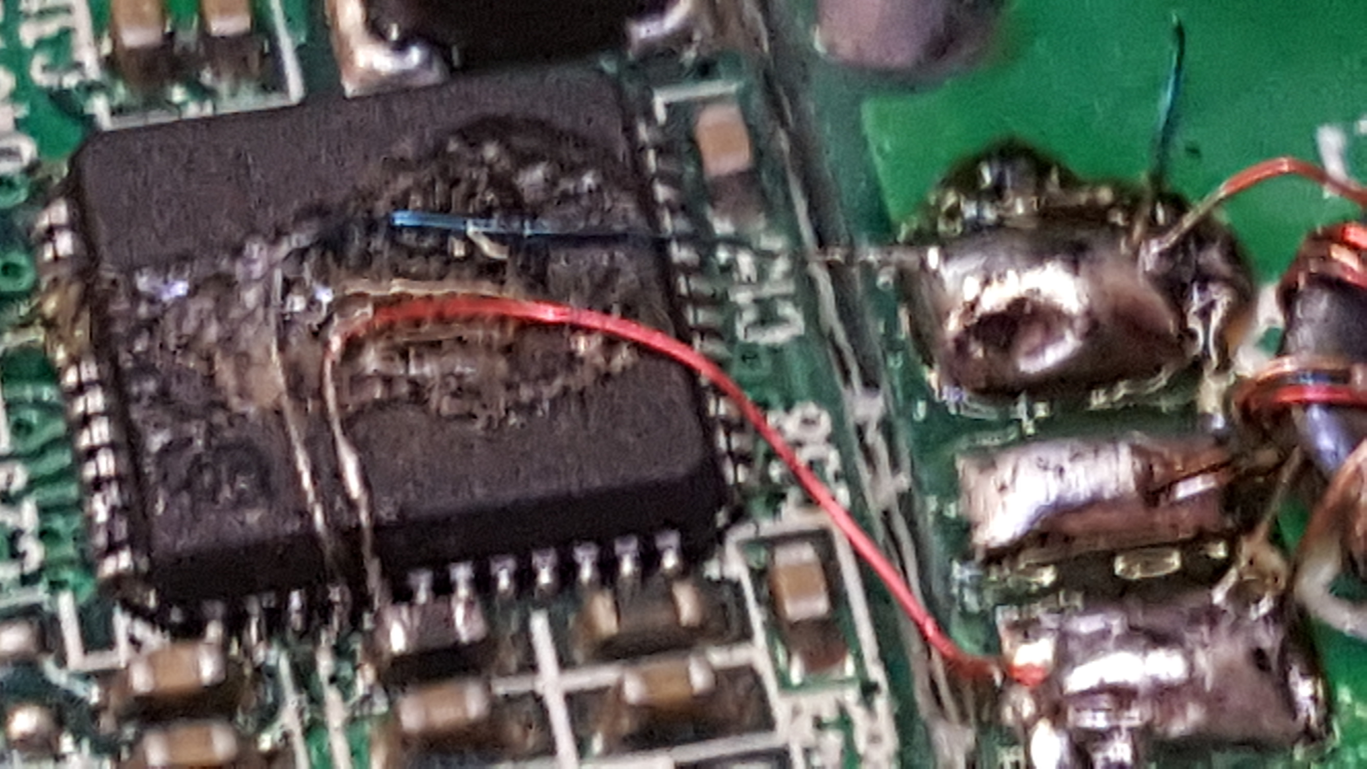 Finally, I used some glue to hold the (very) fragile wires in position and soldered the other ends to the transformer. I also added a small amount of glue to the transformer, too, so as to stop it moving. It looks messy, I know, but hopefully it will add some security and stability to those otherwise poor solder connections to the Realtek chip.
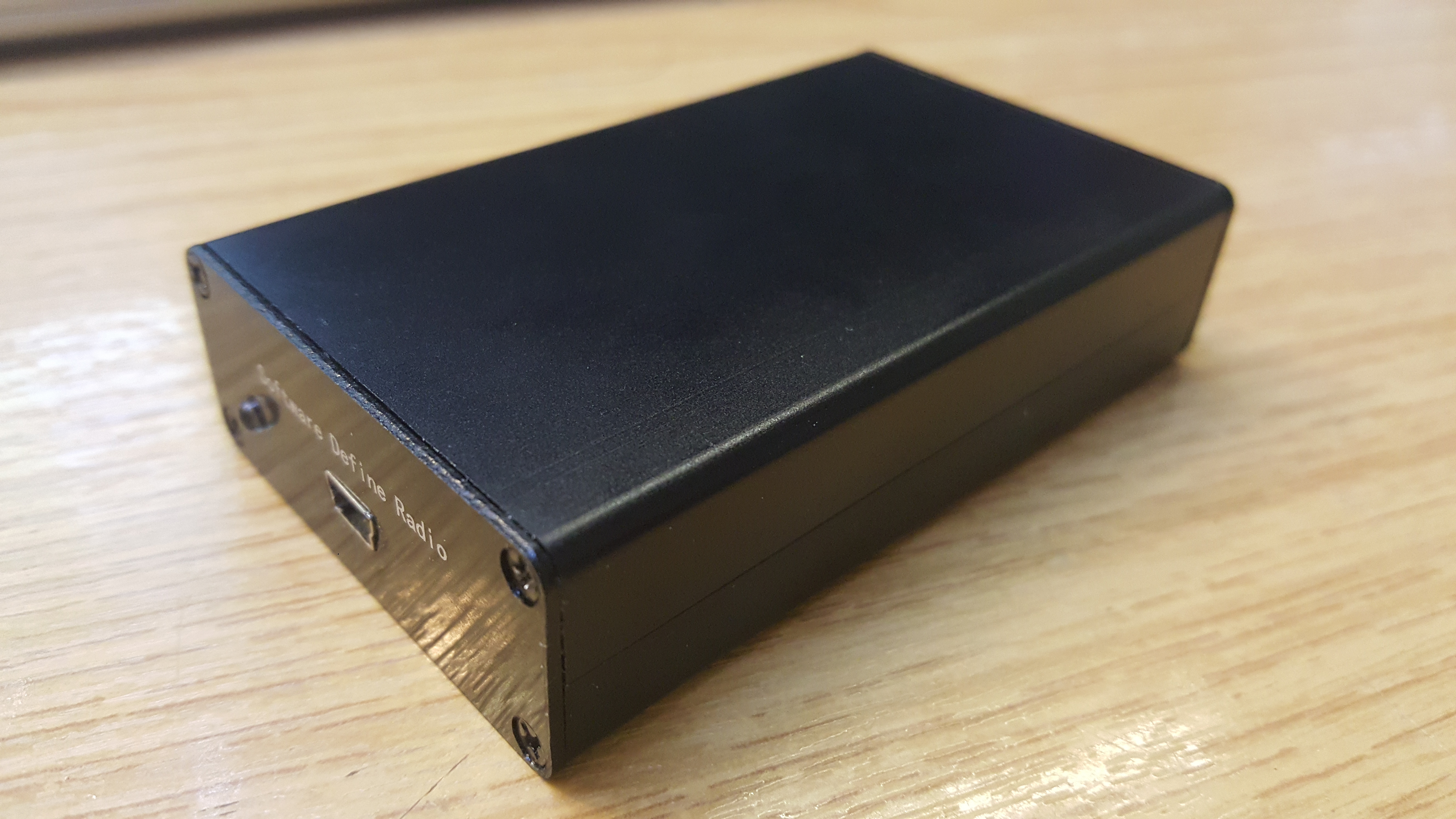
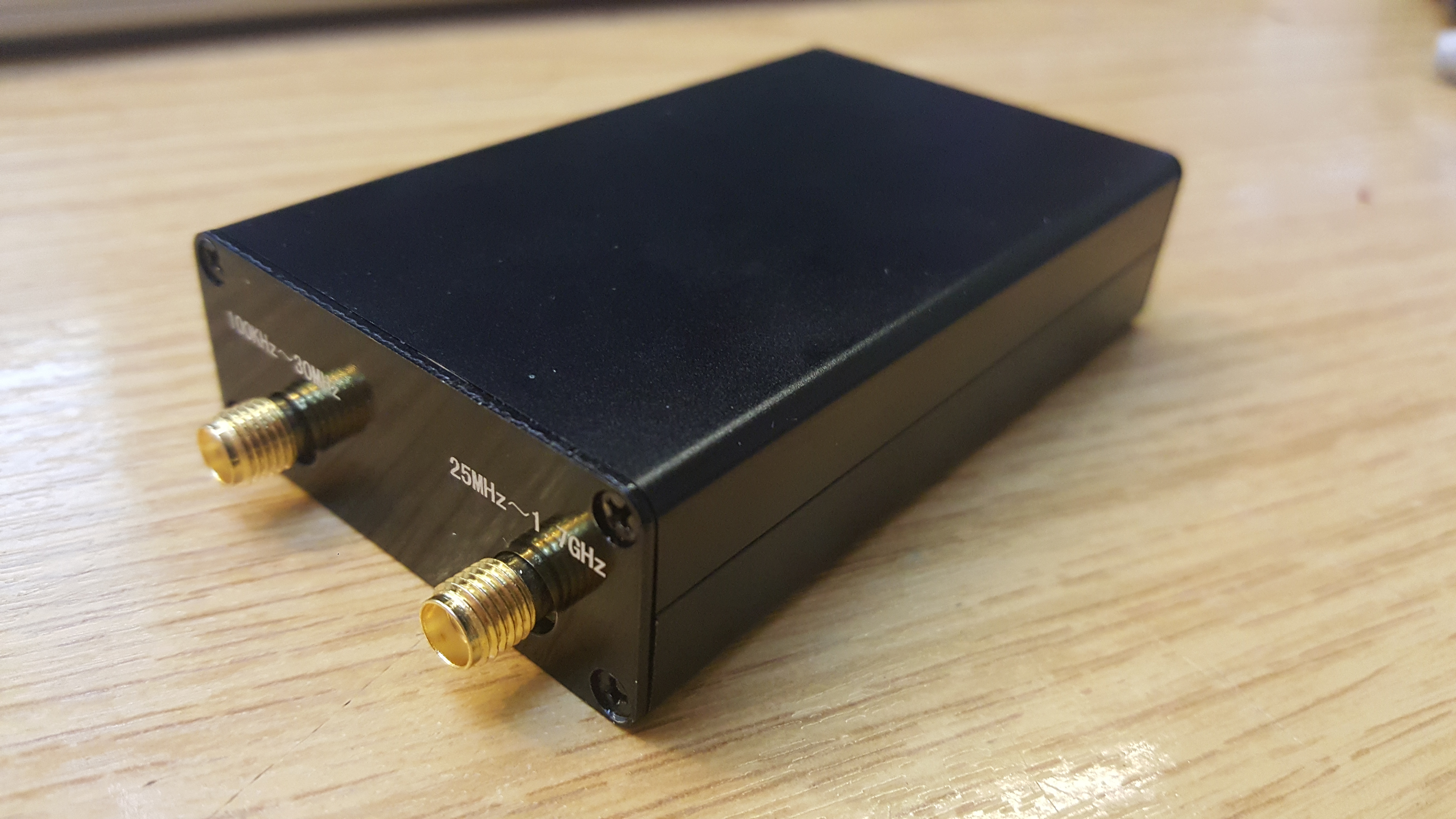
My final build looked like this:
 Amazingly it also works! The image at the top shows the device inside the supplied box! Excellent!