
When doing WSPR on the Raspberry Pi, I needed a bit more current than the standard mobile phone chargers suggested for the Pi could offer. Typically they’re rated at about 1 amp, and will do 500 mA with a clean output supply but much beyond that the output gets noisy and the voltage drops (there are some exceptions). As I was interested in receiving weak radio signals the switching noise from the power supply was a nuisance as was the weird behaviour of some of the peripherals. As you so often see in the Pi forums, “It’s your power supply”.
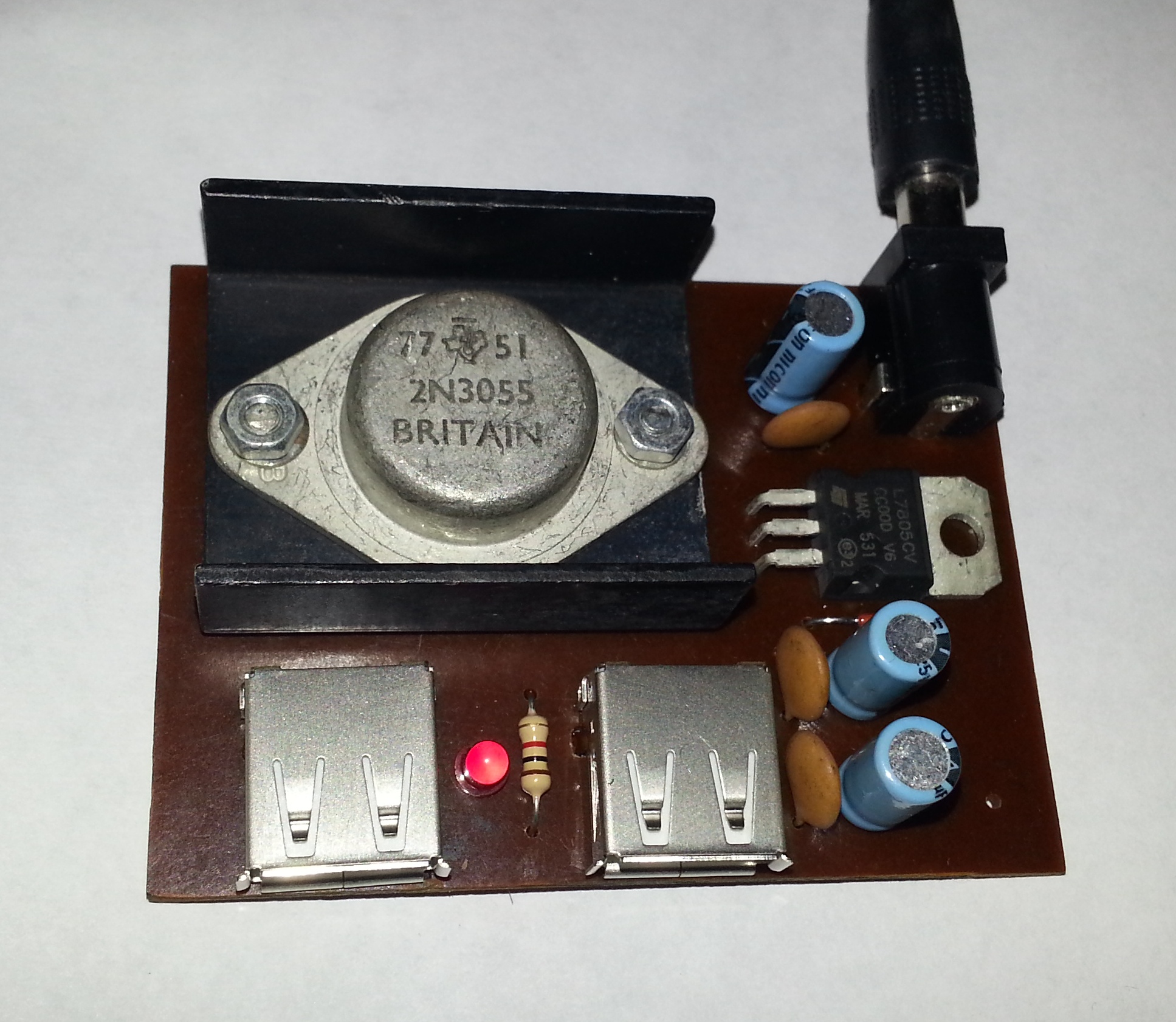
I had originally made something using a 2N3055 in series pass, as shown below, but I came back to this project some years later and refined the approach as well as adding some extra filtering.
The New Design
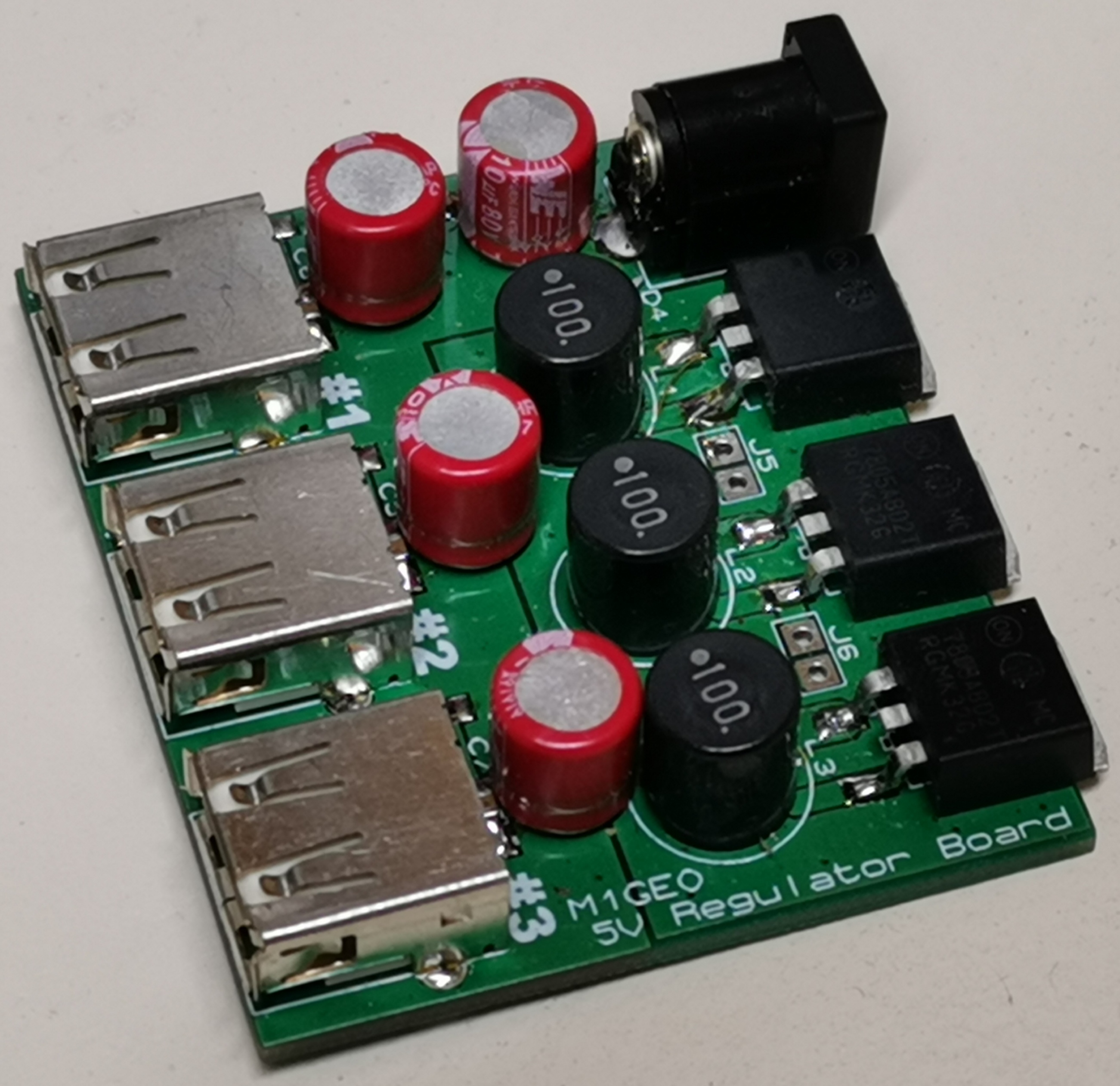
The new design uses three ON-Semi MC7805 devices combined with a Schottky diode to give around 5.2V output. There’s an inductor after the regulator to filter the regulated supply further, and plenty of decoupling. The design offers three 1A outputs, which can be linked to provide a total current of 3A.
Schematic
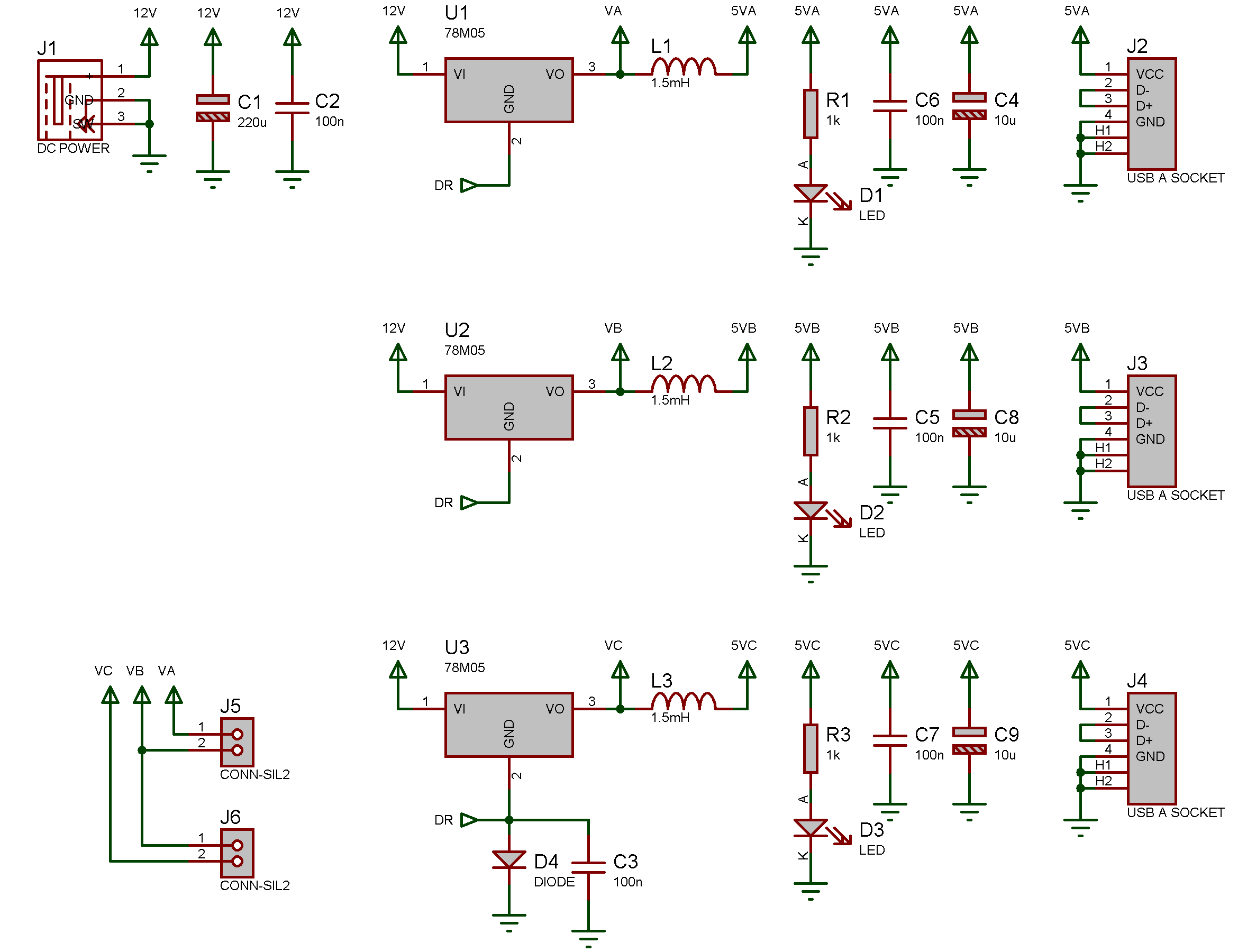
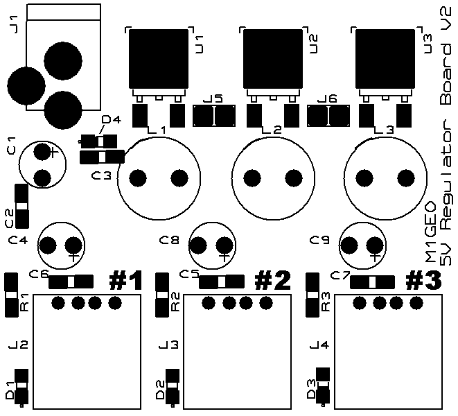
Boards
The board is a 2-layer board with multiple ground zones and is therefore offered as a commercially manufactured PCB.
If you are interested in such a board, please Contact Me.
Bill of Materials
The design uses fairly inexpensive parts, which are commonly available from electronics suppliers as well as places such as eBay and Amazon.
| Component Reference | Component Value | Component Package |
| C1 | 220 µF | 0.125″ pin spacing radial capacitor |
| C2, C3, C5, C6, C7 | 100 nF | 1206 or 0805 |
| C4, C8, C9 | 10 µF | 0.125″ pin spacing radial capacitor |
| D1, D2, D3 | LED | 1206 or 0805 |
| D4 | Schottky Diode | 1206 or 0805 |
| J1 | DC Power Socket | 5.5 x 2.1mm |
| J2, J3, J4 | USB A Socket | Through-hole USB-A |
| J5, J6 | Jumper | 0.1″ pin spacing header |
| L1, L2, L3 | 100 µH | 0.2″ pin spacing radial inductor |
| R1, R2, R3 | 1 kΩ | 1206 or 0805 |
| U1, U2, U3 | 7805 (>1A variant) | D-PAK package |
The Old Design
The design presented here isn’t the greatest or most reliable; it’s the easiest to do the job well. The big 2N3055 transistor used as a series pass transistor is probably overkill for the couple of amps required here, but as it’s well under-rated, it should easily do! It’s important to note that there is no short circuit protection and no over-current protection. Short the output and you’ll get all the current the supply can manage (plus a hot or blown 2N3055). You’ve been warned!
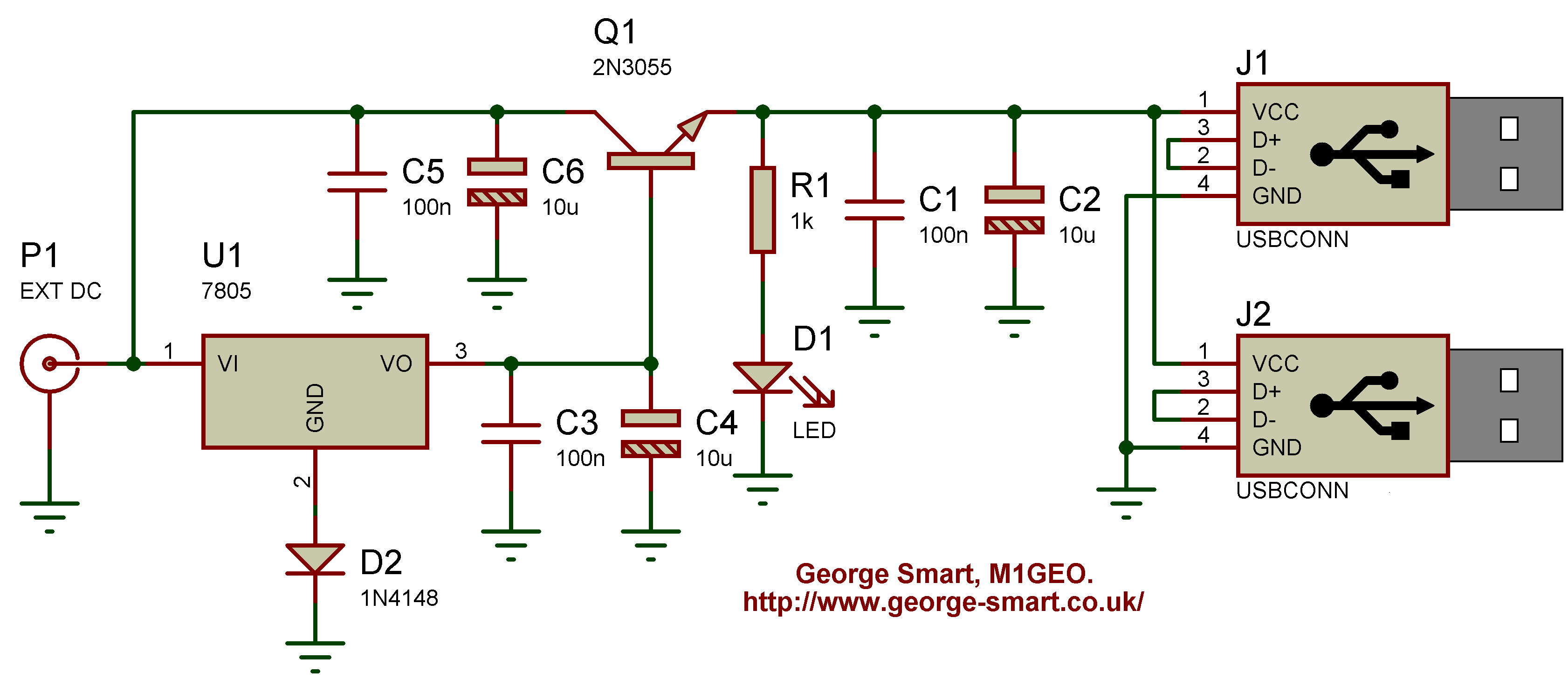
Schematic
Below is the schematic for the regulator. The design is very simple. U1 is a LM 7805 5 Volt regulator. This provides the 5V reference to Q1 which is configured in series pass – the emitter of Q1 is at 5V but with more current than would be provided by the 7805. Diode D2 gives a slight offset to the reference voltage of typically 0.7 Volts which overcomes the 0.7V loss at the transistor’s base-emitter junction.
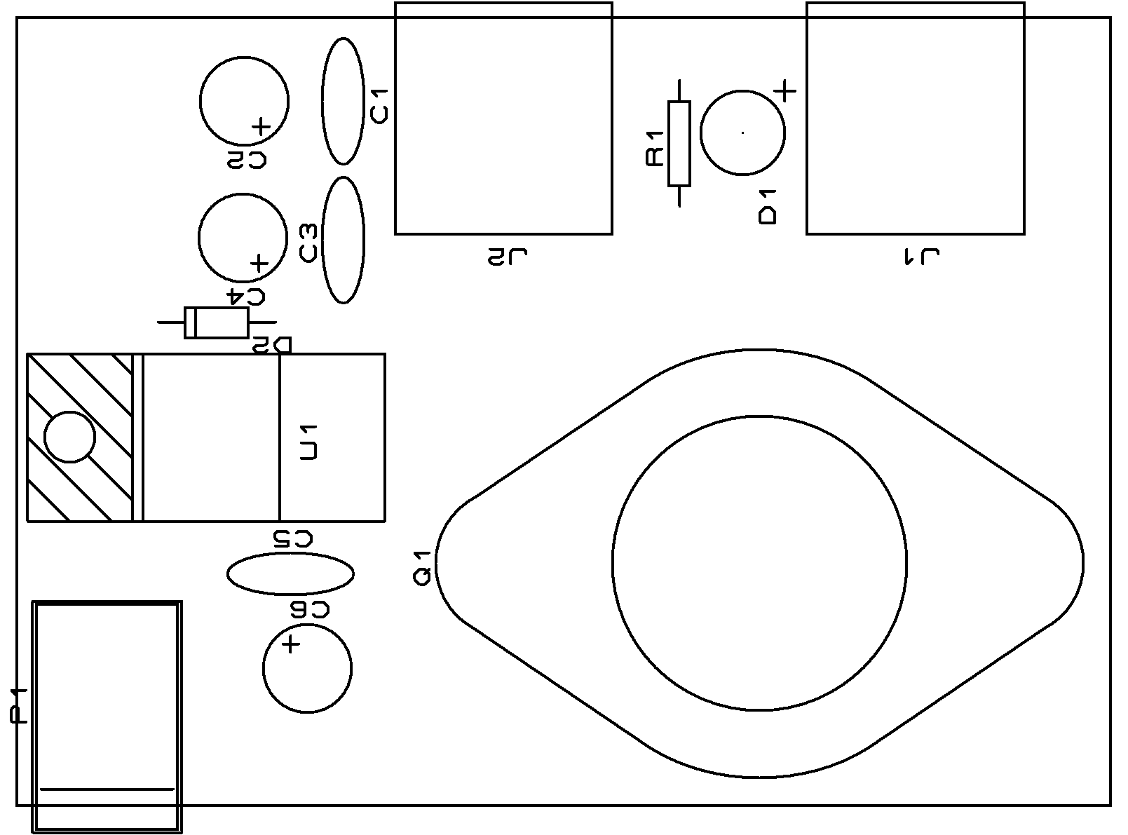
Board
Just in case anyone is interested in making this project, I have included the PCB masks.
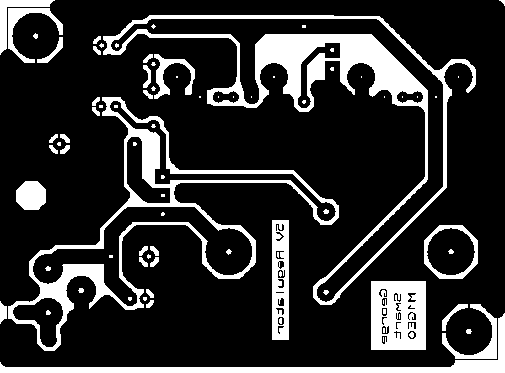
Files
Below are the download links to the board mask and silk as PDF which can be printed at 100% to provide toner transfer or optical masks. Also included is the Gerber files for milling boards.