Tag Archives: construction

A homebrew short loaded whip for 20m & 30m

Final build information at the bottom. STL files here on Thingiverse 7392180.
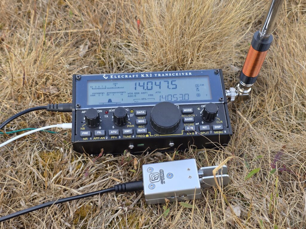
Motivation

The idea of this antenna is to be a small, super convenient antenna for quick activations of parks and summits for POTA and SOTA with Ham Radio. A lot of the locations one may wish to activate are busy, and large HF dipoles are not practical. The aim of this antenna is to get on the air with no external antenna to not annoy other members of the public.

One similar such example of this is the Elecraft AX1 antenna, which covers a couple of bands with a switch: 14 MHz (20m), and 18 MHz (17m) + 21 MHz (15m).

The SOTAreflector is full of AX1 clones like these, but I have decided to add my own here. I wanted to make something elegant, simple and reliable. I wanted to have a way to do a bit of HF on summits that were busy, such as Yr Wyddfa (Snowdon) GW/NW-001. Below, you see how busy it can get – it’s only a matter of time before someone becomes tangled in my HF dipole!

Queues at the Yr Wyddfa summit (image from MountainXperience Ltd, here)

The Beginnings

The basic theory of a loaded whip is to insert inductance in series with an antenna whip to make it electrically longer, despite it’s short physical length. For my use-case, the only practical solution (as with Elecraft’s AX1) is base loading. This is least efficient, but most practical.

I found the longest whip I could; this happened to be 1.2 metres long when extended, and 18cm when collapsed. The base is 10mm diameter and it has 10 telescopic sections.

I settled on making the antenna for 14MHz (20m) band, since it felt like the best compromise between being a busy band and highest frequency (least amount of inefficient loading).

My planned to use the antenna with my Elecraft KX2 transceiver, using the internal ATU to match the antenna, again similar to the AX1. Therefore, a BNC connector would be needed. Conveniently the right compromise between size and strength, as well as matching the KX2. Since the KX2 has a female BNC, the antenna would need to be male.
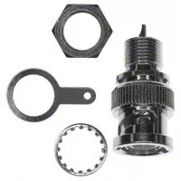
For grounding, I decided to use the ground lug on the KX2 to avoid complicating the antenna design further.

With the key requirements all figured out, it was time to design the loading coil.

The Loading Coil

The loading coil’s job is quite simple; add inductance to the whip to make the antenna seem electrically longer. We’re trying to match the radio’s 50Ω output to the high impedance of the whip — and it will be high impedance since it is considerably shorter than the 1/4-wavelength.

Previously when making a 30m coil for the MA-12 antenna, I used a variable coil and adjusted it to correctly match. However, this was not practical this time around, so I decided to compute things mathematically. To do this, I used John M0UKD’s loaded whip calculator. John’s page goes into the mathematics of the calculation in detail, but for now we just take the result.

I entered a frequency of 14 MHz into the calculator, and a whip length of 1.2m. I set the feeder to loading coil distance to 0m. Finally I took the average diameter of the whip of 7mm. The calculator gave me an inductance of 9uH. Out of curiosity, I tried a frequency of 10.1 MHz, too, which with the other settings unchanged, I got around 18uH of inductance required.

I settled on 15uH with the hope that I could get both the 10.1 MHz (30m) and 14 MHz (20m) bands out of the same loading coil.

From here, I used John M0UKD’s air core inductor calculator to design a coil and assembly I could 3D print. The BNC would fit one end, and the whip the other end. The BNC connector I chose has outer thread diameter of 9.7mm; I printed the part’s connector side hole with 9.3mm so each side would have 0.2mm thread cut in each side. The plan is to screw the BNC in. The whip outer diameter had 10mm.

You can do as you chose to arrive at the required inductance (for me, 15uH), but I settled at a 15mm coil diameter, over 37mm coil length. I arrived at that length by balancing the number of turns required with the wire diameter (0.63mm outer diameter) to settle on 52 turns.

At this point, I knew I needed a 15mm coil diameter, 37mm long, to hold 52 turns of 0.63mm wire. I needed a hole of 9.3mm diameter at one end and 10mm on the other. I added a 1mm hole at each end of the coil. This was easily created in CAD, and before long I had V1 STL files ready to print.
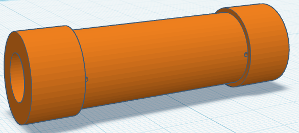
Prototype V1

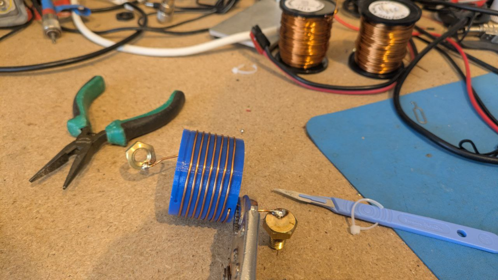
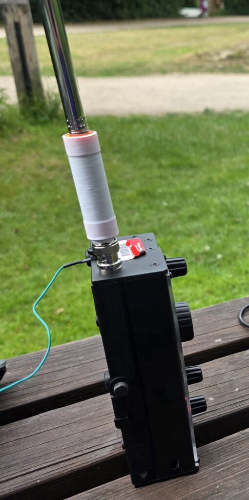
With the coil wound and V1 assembled, I had the bright idea to use an 18650 battery cell heat-shrink sleeve to hold things together. This worked well, but the BNC connector felt loose and fragile in the 3D print, so I tweaked the design further to get the BNC to screw into the plastic tightly and hold well. Full build instructions below.

The V1 in use looked something like the image below, with my KX2 mounted on its side; I plan to use a 90-degree BNC adapter in future, but keen to try it out I jury-rigged the below:
I used the antenna to activate a local park one evening, from POTA GB-5463 (Bramblefields Local Nature Reserve) working 11 contacts on 20m CW. Signal reports ranged from 599 to 319; clearly not the best antenna, but it did get the park activated.
The Final Version

For the final version (currently V5), I ended incorporating a few tweaks, along with printing the coil-former in black, purely for aesthetic reasons. I printed in PETG, but I don’t think that matters much.

To recreate this yourself, you will need:

  • Male BNC panel mount, 3/8-32UNEF thread – I used Amphenol 112420
  • 1.2m telescopic whip, 10mm largest section diameter
  • 3D printed former (download from Thingiverse here)
  • Enamelled copper wire, 0.63mm diameter, approx 2.8 metres
  • Ground wire, approx 4 metres.
  • Heat-shrink to cover – I used 18650 sleeve (optional)

Start with measuring out the enamelled copper wire. You need about 2.6 metres of wire for the actual coil and connections, but you’ll end up breaking the wire a few times trying to get the BNC threaded in, etc., so I’ve added a bit more to it.

Firstly thread the wire from outside of the BNC end into the connector and pull almost all of the wire through. Then feed the inside end back through the coil centre, out of the BNC end and solder it to the BNC connector centre. Leave most of the wire in a loose loop out of the other end – this will provide slack when the BNC is screwed in, hopefully preventing the wire from snapping from the twisting. Take care not to let the wire tie up; unwrap it every few turns so that the wire doesn’t bundle or knot.

Once you have the BNC connector tightly screwed into the plastic 3D print, carefully, without kinking the wire, pull the wire through the hole, close to the BNC so all of the wire is now outside of the coil, and only a short length goes to the BNC centre.

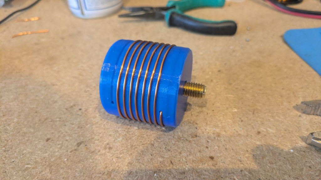
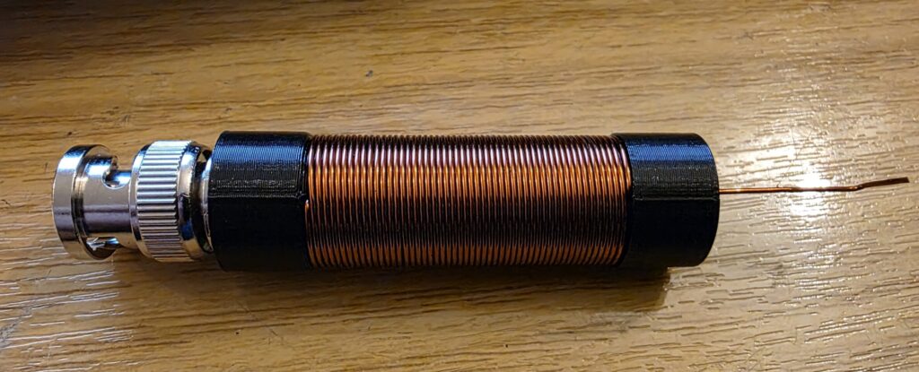
One you’re ready with this, wind the coil. You should take care to get the windings tight, otherwise they won’t all fit in. You need to wind 52 turns around the coil form. Once done, it should look like this…
Finally, connect the end of the wire from the coil to your telescopic whip. The whip I chose has a base part with an M4 screw protruding, so I attached to that inside with a small solder tag and nut & bolt, which gets hidden inside the coil assembly.
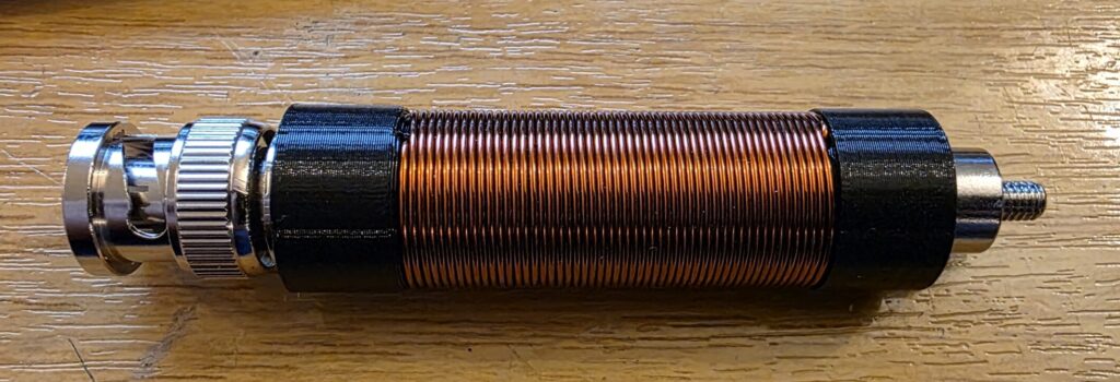
Now just the M4 screw and whip base is visible. The whip can be screwed onto the top of the antenna for use, or removed to pack inside a small travel case with the KX2.

I did a DC continuity test from the telescopic whip to the BNC centre to make sure it was connected, and a second test from the whip to the shield of the connector, expecting no connection – thankfully all was well!

A quick test after building this final version revealed the following on the RBN on 20m at night.
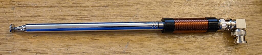
Once everything is working, you can add a tiny bit of super glue to any strategic points, and the finish off with a heat-shrink from an 18650 battery which are very cheap in plain colours and add protection. Conversely, you can get some cool printed designs on them for vape batteries which will add a bit of interest to the antenna!!!

Final Version Testing

When it came to testing the final version, I took the “V5” out to POTA GB-5958 (East Wretham Heath Nature Reserve) on the 5th August 2026. The band conditions were poor on the higher bands, with plenty of QSB but my first contact was with KE1J in South Kingston, Rhode Island; around 3343 miles away. Not bad for 10W into such a compromise antenna!
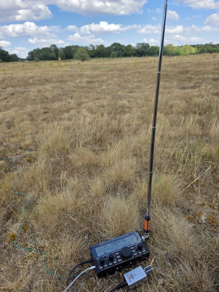
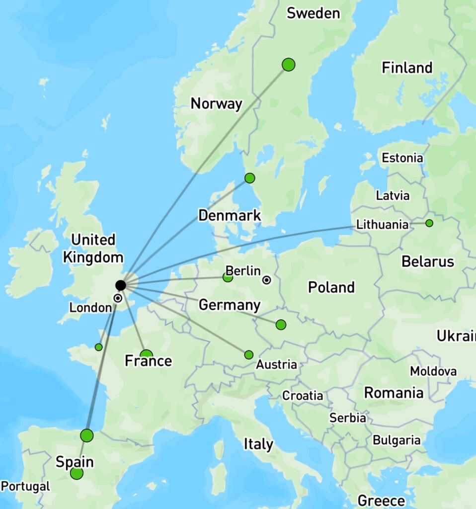
I went on to work 11 more stations, totalling 12 for the activation, and although signal reports weren’t amazing, the log was filling. The map below shows the contacts made on 20m and 30m CW.
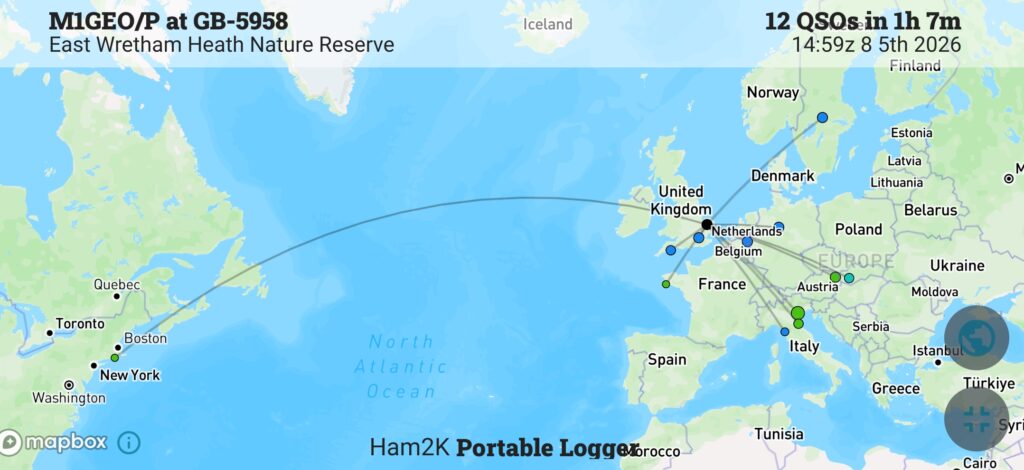
The antenna delivered what I set out to achieve and I’m quite pleased with how well it turned out. It looks tidy and professional, and is very easy to deploy. Its light enough to be part of the standard kit, although I wouldn’t recommend on relying on it, it is a nice convenient backup for when you’ve exhausted VHF for contacts and you need just more QSO for your valid activation.
Homebrew 30m coil for the MC-750 / MA-12 antenna

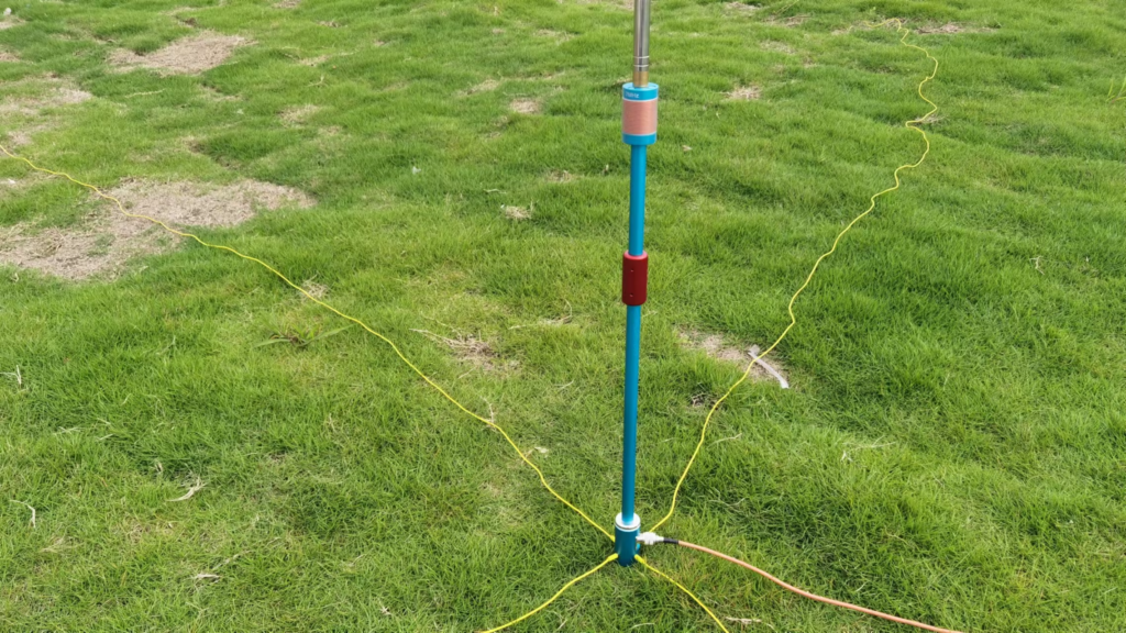
The final STL files can be found at Thingiverse 7267147 – A 30m loading coil for the MC-750 or MA-12 antenna — scroll to the Final Build section for a TLDR.

Background

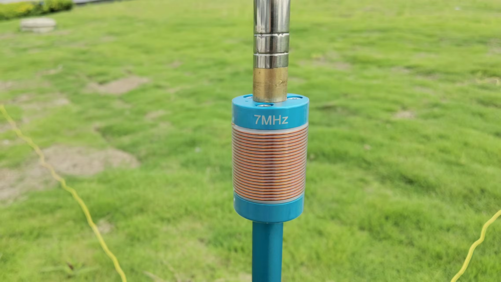
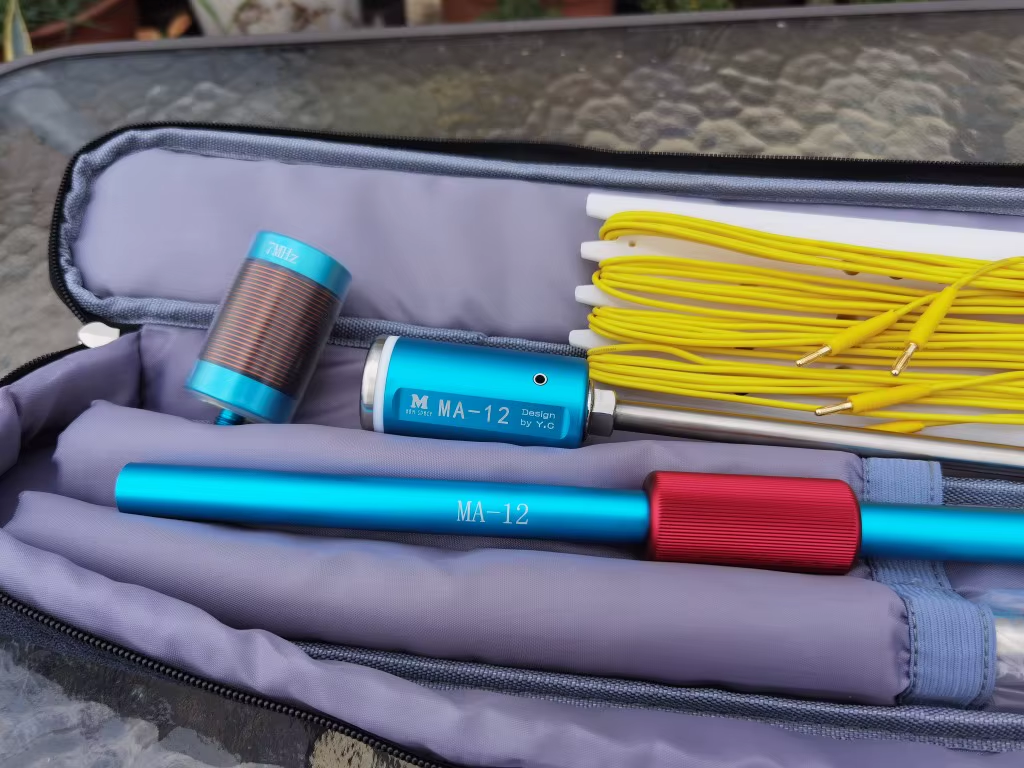
With my interest in SOTA and POTA I have been using an MA-12 vertical antenna for activating since it is convenient and quick to get on air. It seems identical to the MC-750 by Chelegance, but half the price!

I really like the antenna and it performs well since on the higher bands it is an unloaded vertical. On the lower bands, the antenna comes with loading coils for 40m (7 MHz) [supplied] and 80m (3.5 MHz) [optional]. These are fixed coils, made from copper wire, and so avoid the higher resistances seen on coils made using stainless steel like that of the JPC-7 antenna which uses a variable inductor.

Combined with my learning CW, I have an interest in the 30 metre (10 MHz) amateur band which the the MA-12/MC-750 doesn’t cover (it does, but clearly as an afterthought).

On 30m, the operating manual for the antenna says to use the 7 MHz loading coil and reduce the length of the whip down. Doing this you are able to get the antenna to resonate within the 30m band, but it leads to poor efficiency since most of the whip is collapsed and the antenna is significantly shorter than it could be if the loading coil were sized correctly. So why not make a coil for 30m…

Cue this page…

What inductance do we need?

To find the inductance needed I decided to use the aforementioned JPC-7 variable coil in place of the 40m since it can be adjusted – this meant I could iteratively sweep through all the inductor tap points and see where the antenna resonates.

Clearly there are many combinations of coil inductance and whip length that will work, so I settled on having the whip as long as practical. Rather than using the full length of the whip (5.2m), I opted to leave one section collapsed allowing for some room to adjust depending on ground conditions (rocky, wet, dry, etc.). This left me with a whip around 5 metres long.

Starting at minimum inductance (top, closest the whip), I could see the antenna’s resonant frequency at around 12 MHz, and as I repeatedly clicked in another turn of inductance on the JPC-7 coil, the resonant frequency dropped.

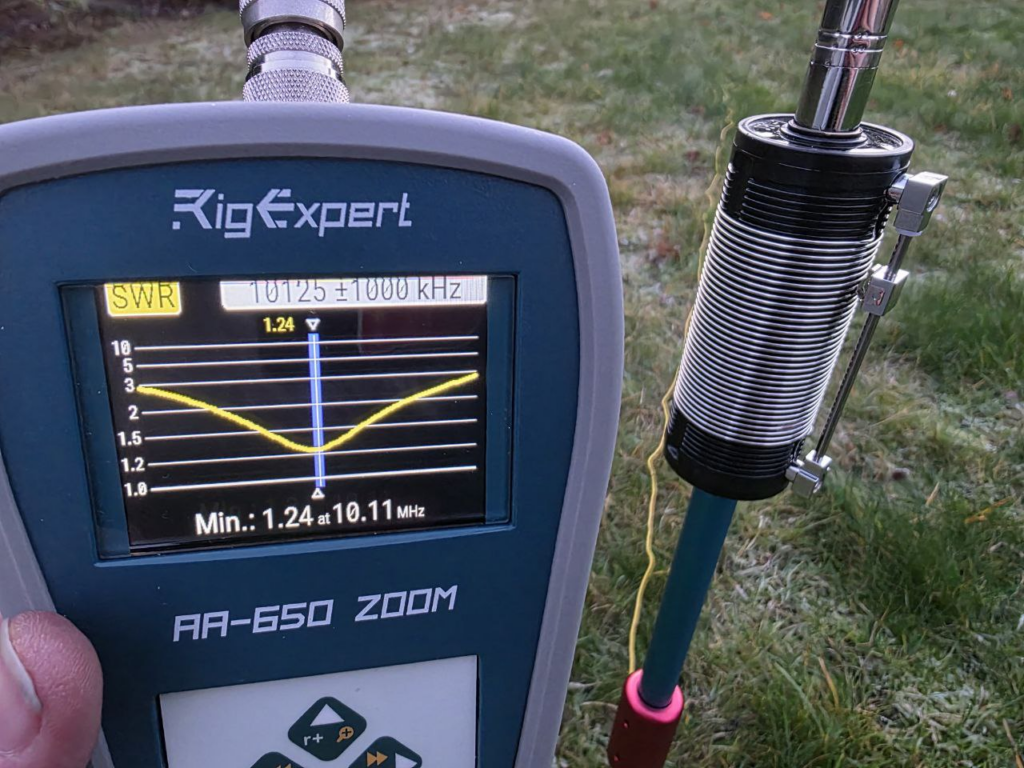
At 10.8 MHz, I knew I was close, and since an additional turn on the coil took me to 9.9 MHz (below the target of around 10.125 MHz) I went back to the 10.8 MHz tap point, and lengthened the last whip section slightly. With 1/4 of the section extended, the resonance was on 10.11 MHz near enough. The tap was set to 7 (complete) turns.

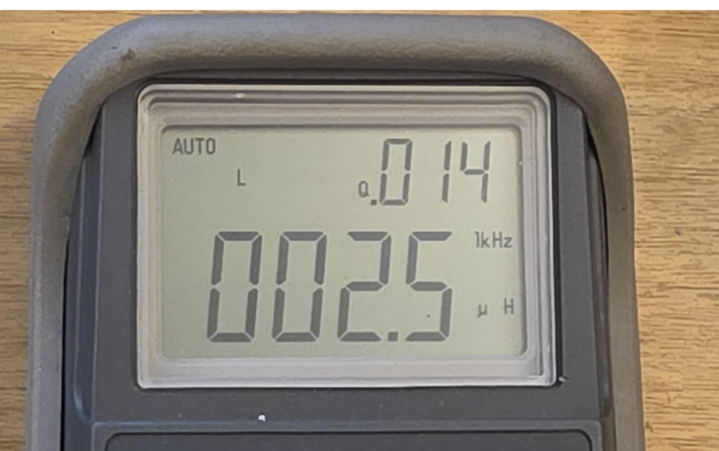
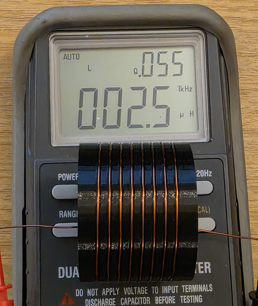
Nice! It was then just a case of measuring the inductance between the two M10 fixings to determine what inductance was needed:

As can be seen from the LCR meter display above, the measured inductance was 2.5 μH after calibrating the test setup.

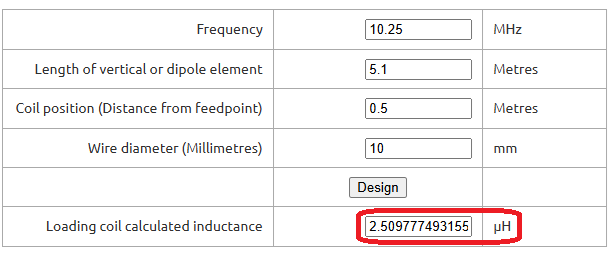
To confirm this was sensible, I put some numbers into John M0UKD’s Loaded Quarter Wave Antenna Inductance Calculator and checked the results. Amazingly, they agreed very well – the calculator predicts 2.51 μH. Wow! I wasn’t expecting that!

For what it’s worth, I run the numbers on the JPC-7 coil, and 7 turns on the 41 mm former over about 10 mm works out about 2.9 μH. Not quite as close, but certainly within measurement errors.

Confident that I had found the right inductance, I then had to make something suitable.

Making an inductor

Since I wanted to be able to 3D print the design, a larger diameter coil would be advantageous as it both reduces the length of the coil (and thus leverage from the whip) and increases the glueable surface area (increasing bond strength). Brass M10 nuts and bolts can be purchased cheaply enough in small quantities that it avoided pulling in favours from friends with a lathe, so I chose that route for the connections. Brass can be soldered to, which was the attraction there.

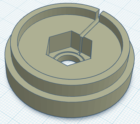
With that in mind, I created the end caps with recesses for holding the nut & bolt tightly. The diameter I chose – based on feel – was 50mm outer diameter, with an inside diameter of 45mm, creating a wall thickness of 2.5mm. A 6mm overlap should provide ample overlap to glue everything up once built. A groove on the inside provides a location for the wire to be trapped under the nut/bolt should the be preferable, though I plan to solder to the fixings. A thin brass washer may also be used.

With the end caps designed, I just needed to work how many turns we would need. This is a bit of a juggling act, since everything about the coil affects everything else – it’s just a case of starting somewhere and tinkering until you get everything in harmony.

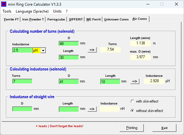
For these projects, mini Ring-Core-Calculator by DL5SWB & DG0KW is the go-to. The calculator has an “Air Cores” mode which fits our needs perfectly. In the top section, you’ll see the desired 2.5 μH inductance, the 48 mm diameter (50 mm minus 1 mm for wire diameter), and the coil length – here I chose 30 mm as it looked about right; the tool tells us we need 7.54 turns.

Note; in the middle box you also see the 7 turns on the JPC-7 coil’s 41 mm diameter former over 10 mm equating to around 2.9 μH. These were just rough measurements taken from the JPC-7 coil used above to further sanity check our numbers.

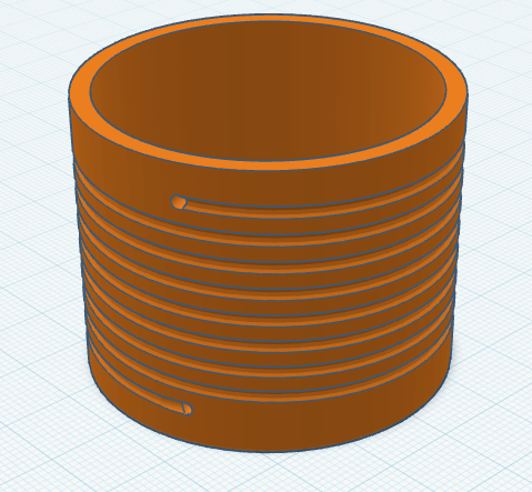
With those numbers from the tool for our coil in mind, it was time to create the coil former. This is a fairly simple task for someone competent with CAD, but it took me the best part of an hour to get this designed matching what the calculator told us.

When creating the model for the former, I used 8 turns and then added a hole half a turn back for 7.5 turns too. This allows us the option if needed, but the couple of prototypes I tested showed 7.5 to be the best option (8 turns had 2 sections of whip collapsed in, but also worked fine).

The image below is the 8 turn coil, though latest update shortens it a bit on each end to keep it compact.

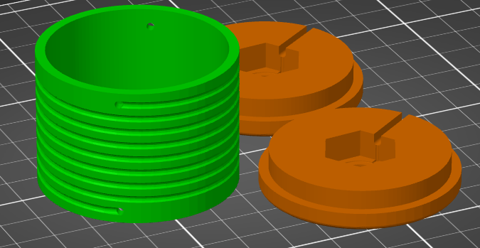
Once everything was designed it was time to fire up the 3D printer and get working. If you don’t have your own 3D printer and wish to follow along, many online services like JLC3DP or PCBWay 3D Printing can help – I’ve no affiliation to either, but have used both services more than once with good results – or ask at your local radio club or maker space. Everything will fit on a very standard 3D printer, there’s nothing special here. You may wish to consider the stresses and sheer lines in the print for longevity, but for these parts you see here – the first prototypes – I just printed them as quickly as possible.

Perhaps use a higher infill on the end parts, as they may see leverage from the whip on quite a small area under the nut. I’d recommend 50% infill under the nut & bolt, and then reduced away from that. Though try it first and reprint if they fail?

I printed my parts in PETG as it’s better in UV light and a bit better at handling heat than PLA, but in reality anything should be fine. 0.2 mm layer height, 0.4 mm nozzle, 20% infill, but as I say, whatever you have will be fine! There’s nothing special here. Printing took around 3h45m, used 42g of PETG, costing approximately 2 USD.

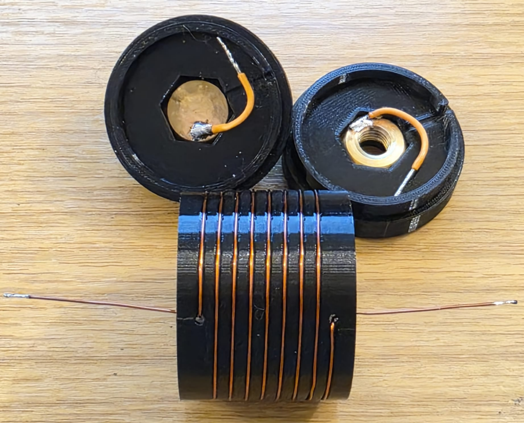
Once your prints are done, you’re ready to wind the coil! 8 turns of copper wire, with the ends finishing inside the coil, since that’s there they’ll connect to the nut and bolt – leave the wires on each end long for now so we can connect things up! The coil calculator tool suggests 1.13 metres of wire is needed for the coil, so I cut 1.2 metres (4 ft) from my reel.

Be careful when soldering not to melt the 3D printed former, especially with heat tracking back up the coil wire through the holes. Solder to the nuts and bolts outside of the plastic. Above I just have some test wires connected, but they’ll be replaced with the proper wire from the ends of the inductor on the real coil.

At this stage, if you can, I’d recommend checking the coil inductance. We’re targeting a 2.5 μH inductance and as you can see below we’ve got that. This meter lacks precision, but we’re at least in the ballpark. Note that the Q-factor is 55, which is a little low on this test coil; I suspect due to using thin (0.6mm diameter) wire. For a 2.5 µH air-wound inductor such as ours, the expected Q-factor typically ranges between 50 and 200 for general-purpose designs and we’re at the very bottom of that range.

An interesting aside, the Q-factor for the stainless steel JPC-7 was very low at just 14 (seen in the image above). Other people have noted this before and Clint KA7OEI has an article on rewinding the JPC-7 using silver coated copper wire to significantly improve its performance but Clint reports seeing Q-factors as low as 11 on the original coil on the 20 meter band and slightly better at the higher inductances needed for 80 meters, with Q-factors of around 30. These values increased significantly to around 60 with standard copper wire and up to around 150 with thick silver coated wire; so once again we’re on the right track given the thin wire I’m testing here. I haven’t got anything suitable to hand but I have ordered some standard 1mm diameter copper wire.

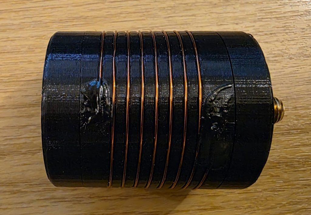
Now lets bundle it up into a coil and see if it works! I used a combination of glues to hold the wire into the coil former; superglue on the wire, holding it into the hole; liquid electrical tape atop, to protect the superglue and help with weathering. Each was allowed to set fully before applying the next. I then made the connections to the nuts and bolts, ensuring the wire did not coil up inside the first. Keep connections at right-angles to the coil, and avoid loops. From the outside, mine looked like this.

Testing

Once the prototype was ready, it was back out into the (cold, −3C) garden to test things out.

[[VSWR PLOT HERE]]

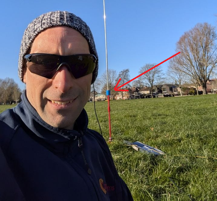
With the VSWR plot looking OK, I managed to convince Rob M0VFC to come out portable with me to Stourbridge Common Local Nature Reserve in Cambridge to activate POTA GB-5467. Rob took on the task of trying the coil out on 30m, and had it up and running in no time, having easily found resonance using the Elecraft KX2 built in SWR meter. Rob took a selfie while I was operating and you can see the coil on the antenna encased in blue heat-shrink to help hold things together.

Image courtesy of Rob M0VFC

Final build

The final STL files can be found at Thingiverse 7267147 – A 30m loading coil for the MC-750 or MA-12 antenna. You’ll need to print two end caps, and one loading coil centre.

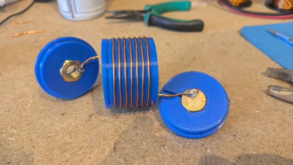
After a couple of POTA activations with the coil, it turns out that 7.5 turns allows for slightly more whip expanded, and therefore theoretically fractionally better performance. Below, Rob M0VFC’s build of the coil with 7.5 turns, showing the internal assembly steps.

Once assembled internally, a couple of drops of glue can be used to secure the nut and bolt in place – taking care not to get it on the threads – and then to close the case up fixing the ends on with glue.

All images in this section kindly supplied by Rob M0VFC.

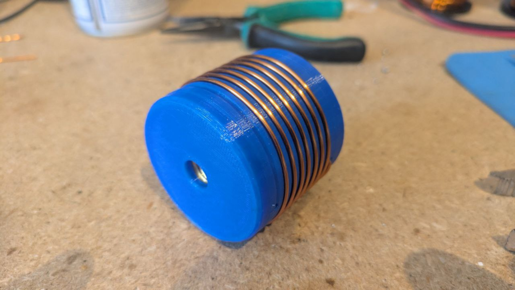
Finally, some plastic shrink-wrap or heat-shrink can be used to protect the coil and finish the project.

1kW 144MHz Amp Lives!

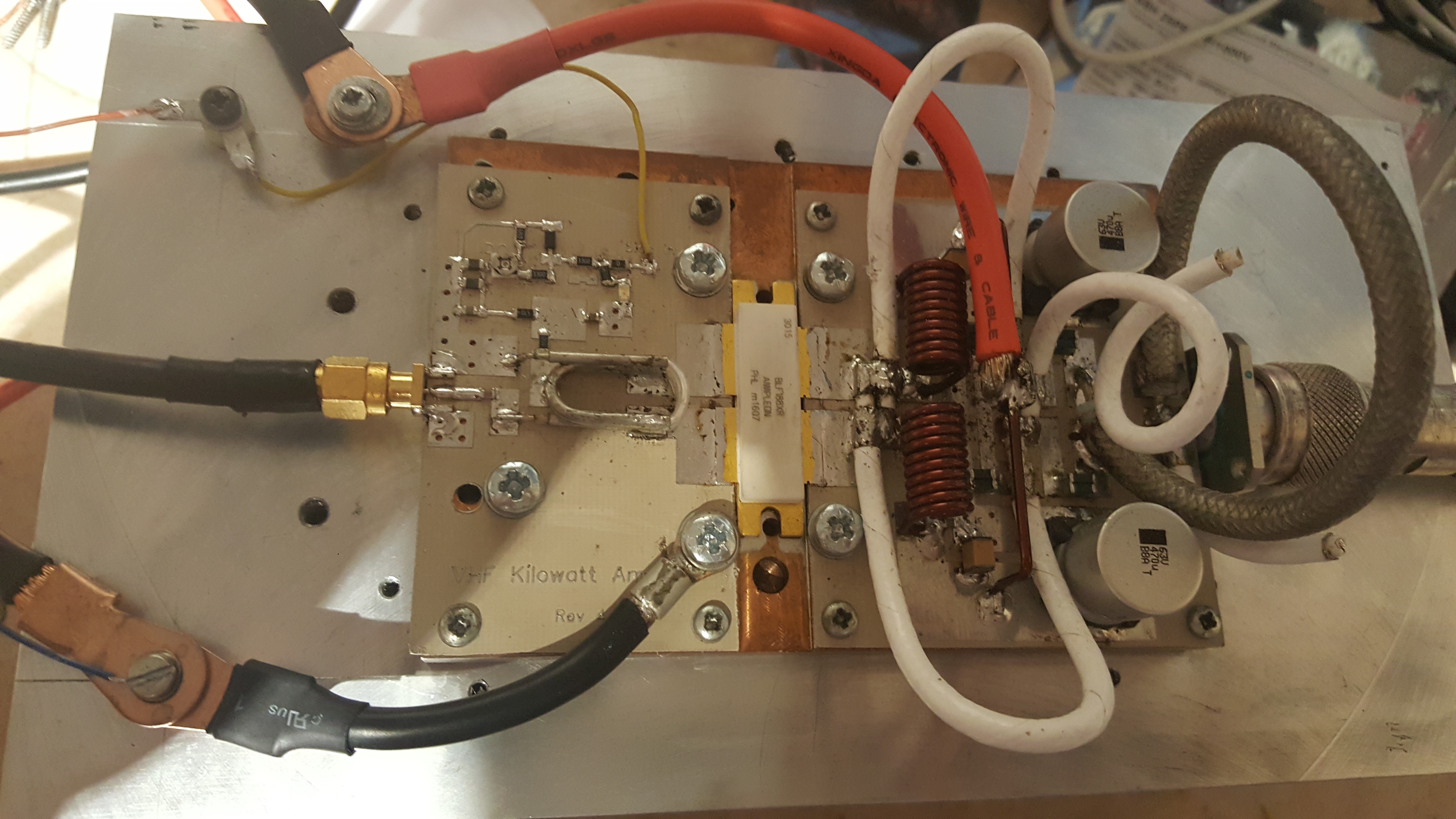
Those of you who have been following my 144 MHz 1kW amplifier project (previous posts machining heatsinks, soldering transistor down and building the pallet) will, I’m sure, be delighted to hear that I have had life out of the amplifier. In excess of 1 kW, I hasten to add!

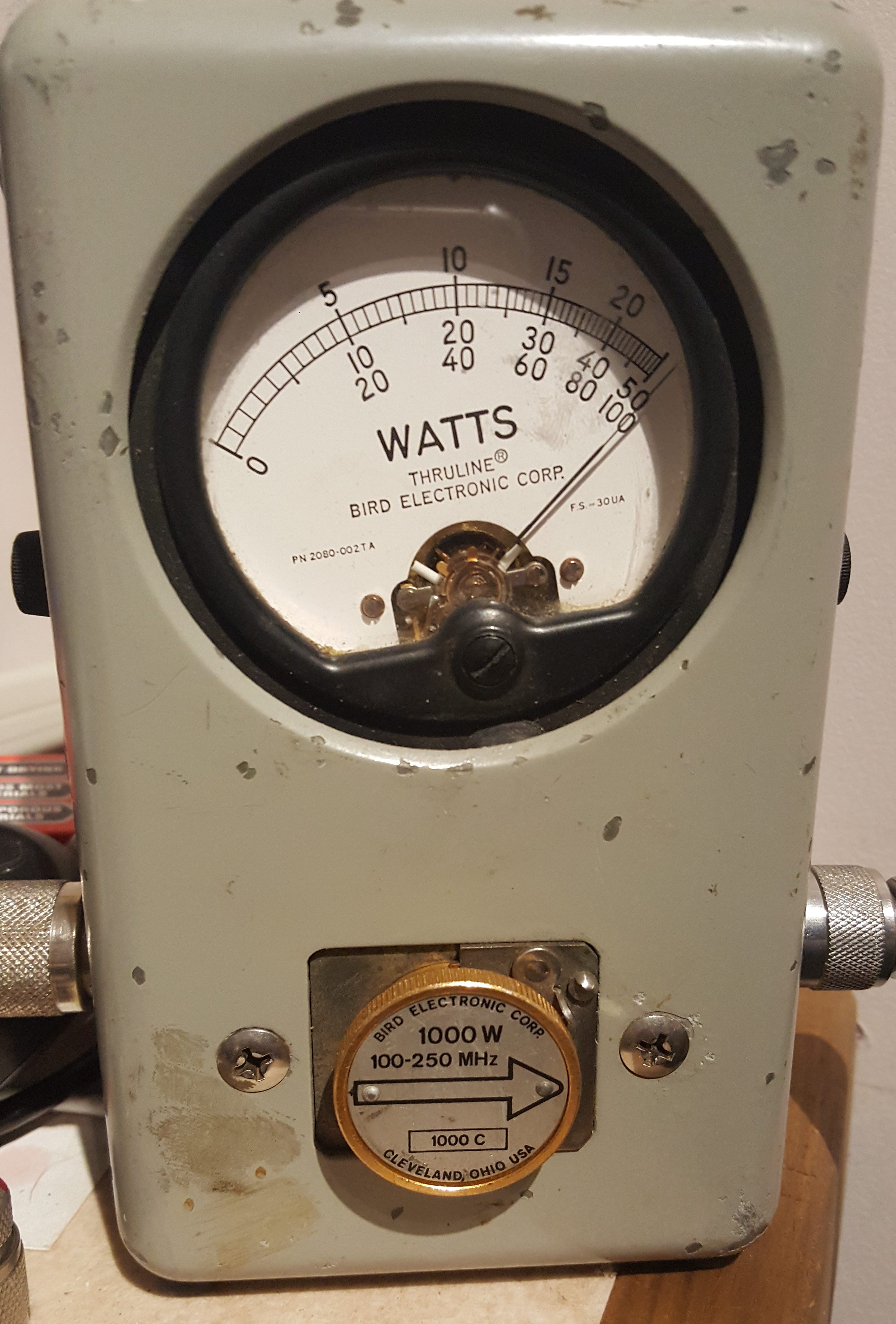
The amplifier was able to maintain in excess of 1000W for over 2 minutes.  At this point, the Bird dummy-load started to get a bit warm, so a longer test was abandoned. The amplifier pallet, however, remained cool enough to touch. As the F1JRD original design notes, the 10-Ohm coax balun does become hot (Lionel suggests around 120C at 1kW with no cooling). I, however, used a small fan running slowly to provide a gentle draft which greatly reduced the balun heat.

The next step is to add the Dallas-Maxim DS18B20 temperature sensor – the idea is to have the sensor buried into the pallet next to the transistor, to measure the copper heat spreader temperature.

Soldering Expensive Transistors

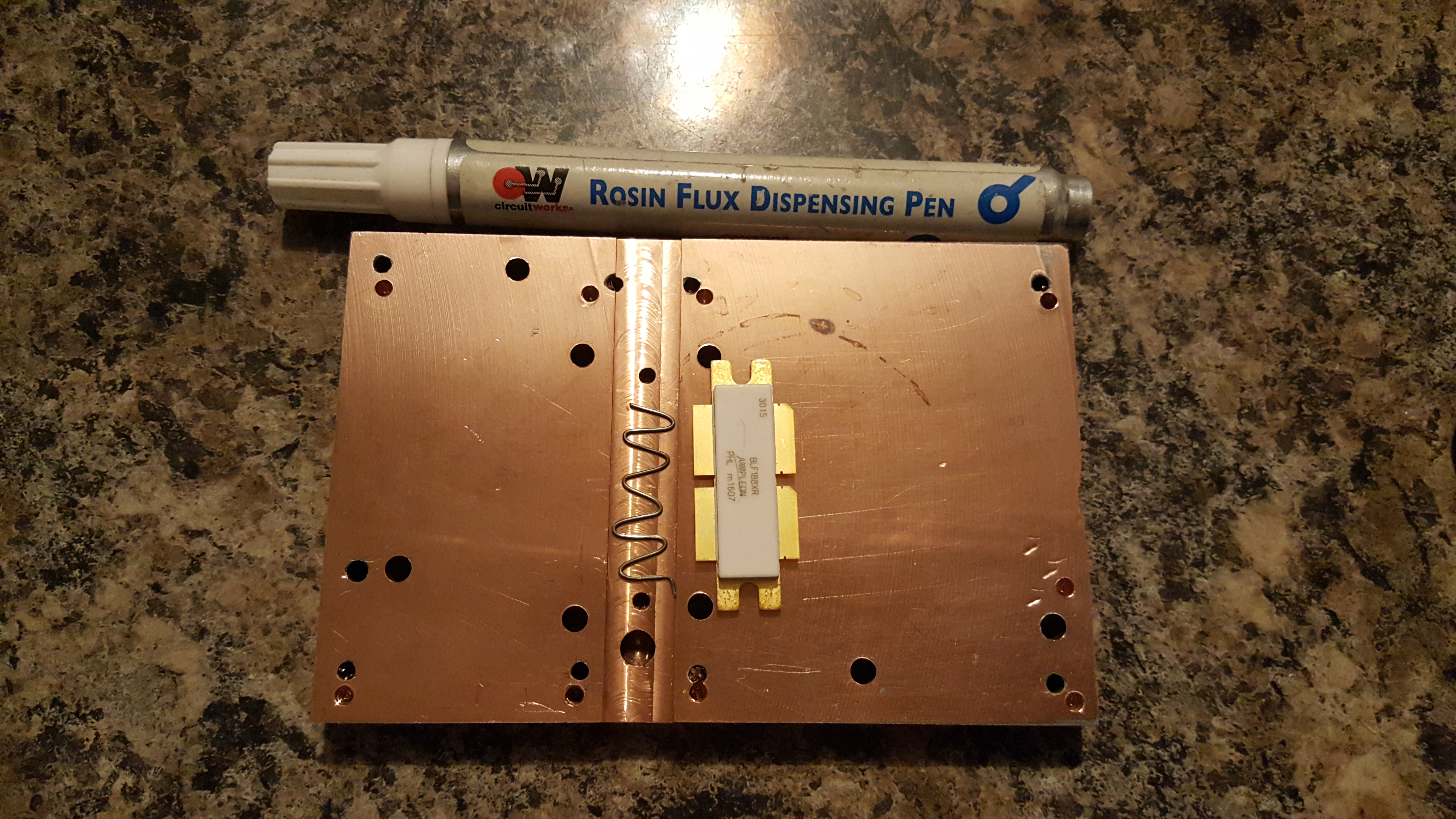
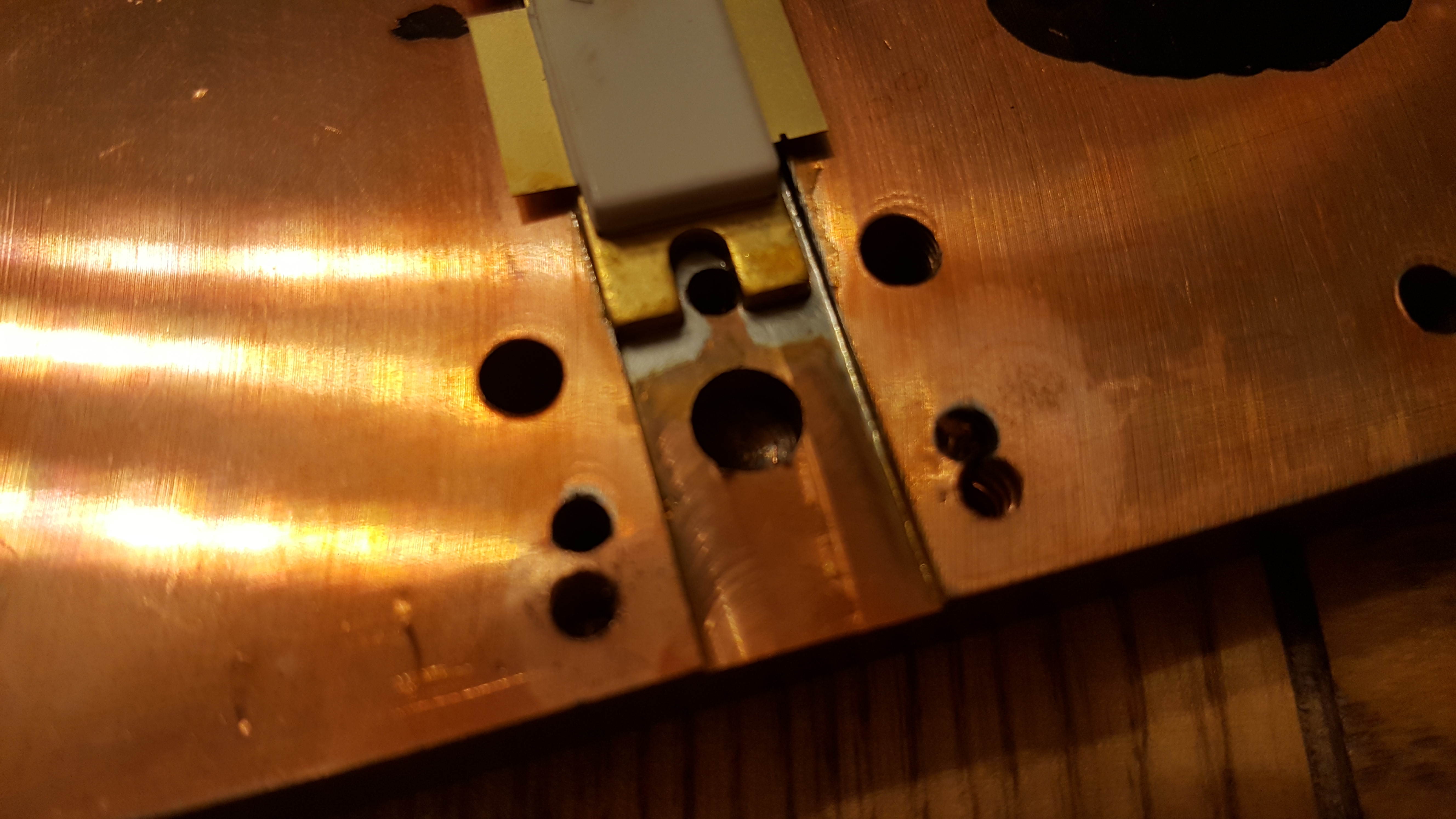
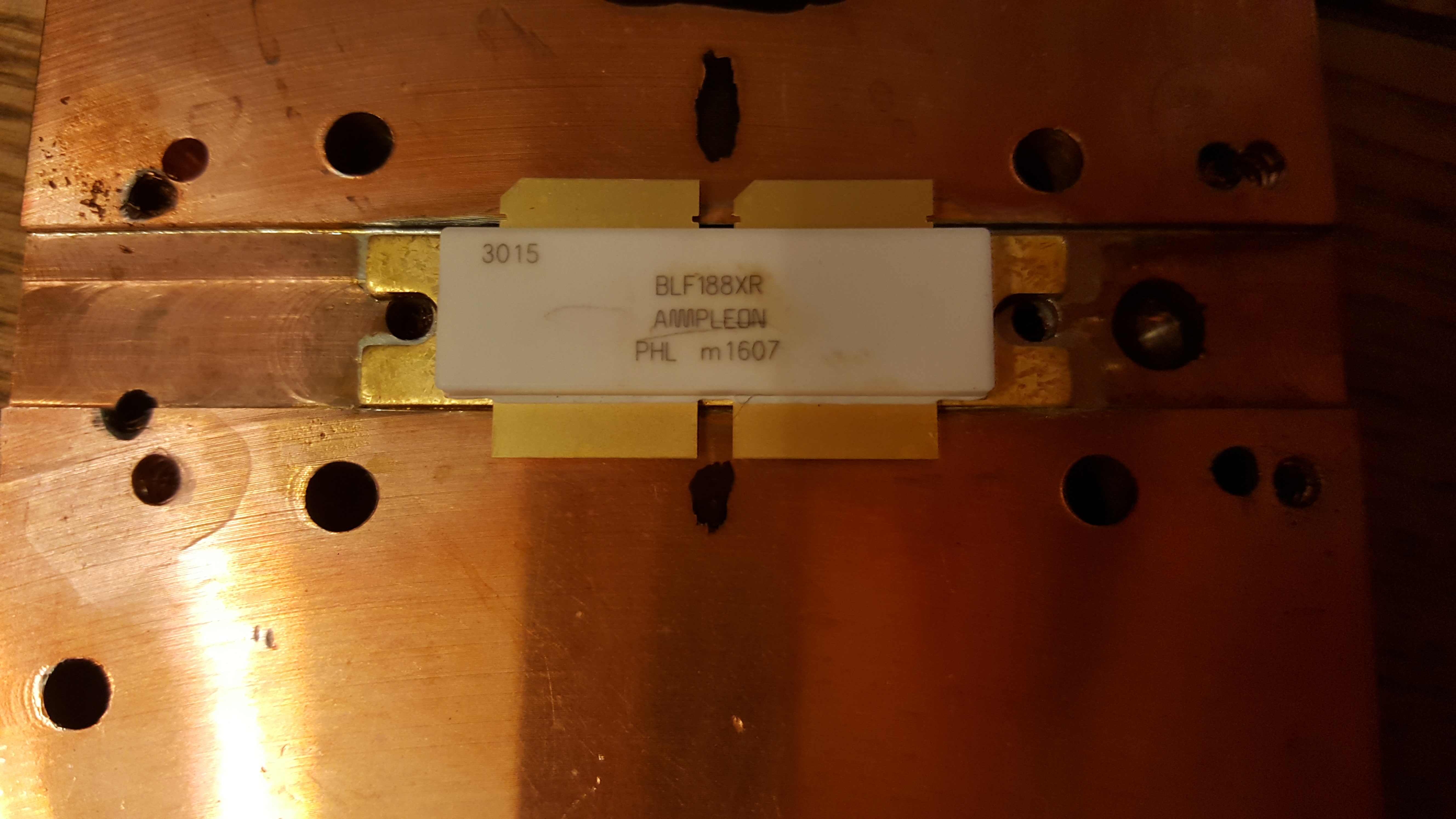
This morning, Royal Mail delivered me a parcel from Jim W6PQL all the way from California, USA. It took a couple of days to clear customs, but it arrived within about 5 days of being ordered. If you followed my previous post on this subject, about machining heatsinks, you’ll know that the last transistor I had failed on the testbench. You’ll also know that the copper heat-spreader was re-machined to suit the new PCB. This is why the heat-spreader has a few extra holes. Seeking advice from veteran microwave DXers & constructor (G4BAO, G4DDK, G8KBV, et al.) I was instructed to solder the device down. I watched a few of Jim W6PQL’s videos on soldering LDMOS parts to the copper heat-spreaders and replicated his instruction as closely as possible. You can see Jim’s instruction video here.

A small length of thin leaded 60/40 solder was made into a wiggle for the length of the transistor and placed in the groove previously machined in the head-spreader. I liberally applied flux to the bottom of the groove and the underside of the transistor and then sandwiched  the solder in between.

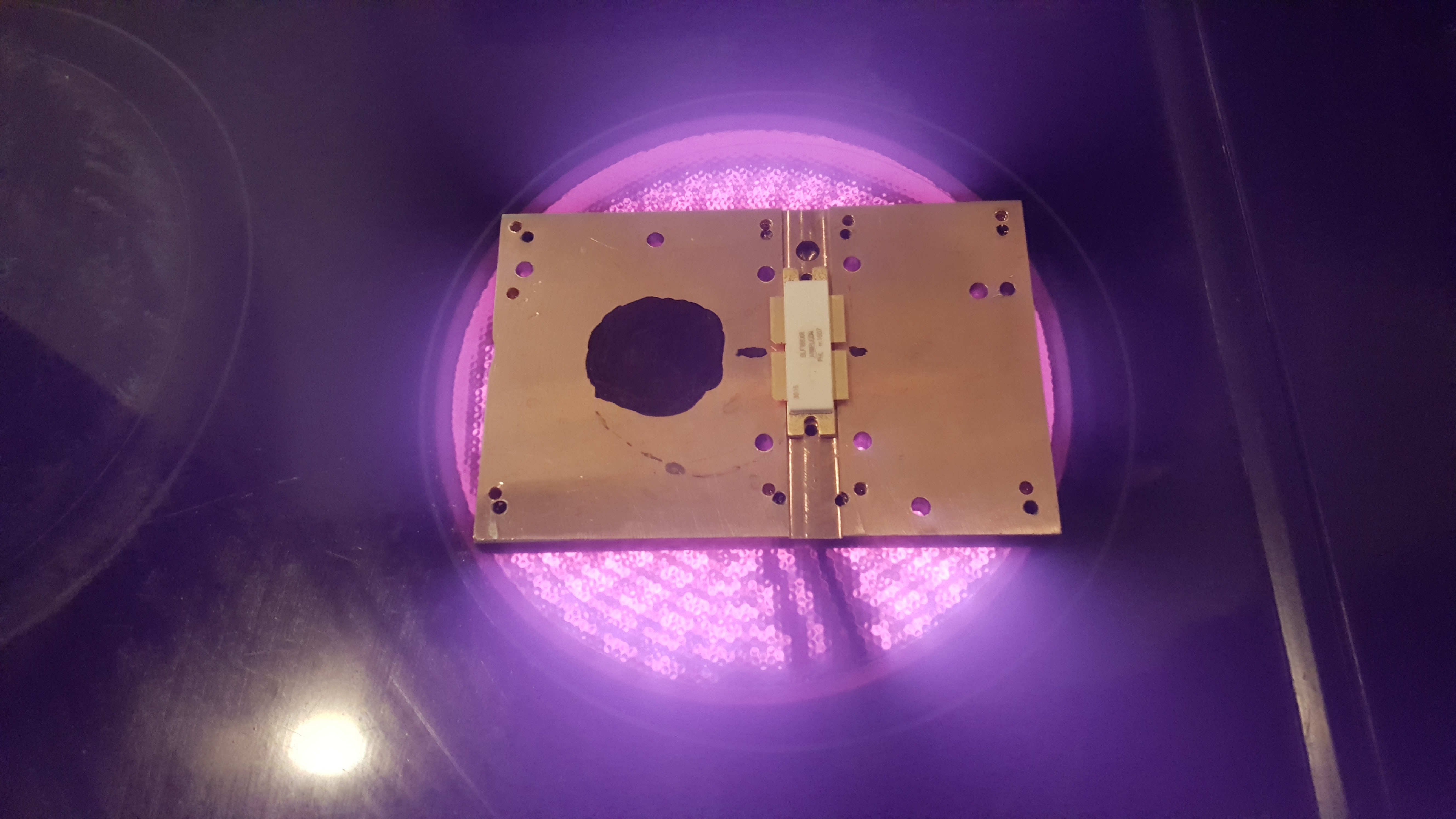
The copper heat-spreader was placed on the electric infrared hotplate and heat applied. The black dot is used to allow a laser thermometer to monitor the copper temperature. NB: this method didn’t work well.

The next two images show the solder has melted and the excess squidged out the sides. It’s clear to see when the solder has melted, since the the transistor drops. It is advised to move/slide the transistor in the molten solder to remove any voids and any excess solder. I immediately killed the heat and removed the spreader from the hotplate and placed it on a heatsink. It only took a couple of minutes to cool to a temperature I could handle, and I checked the location of the transistor against the PCB mounting holes.

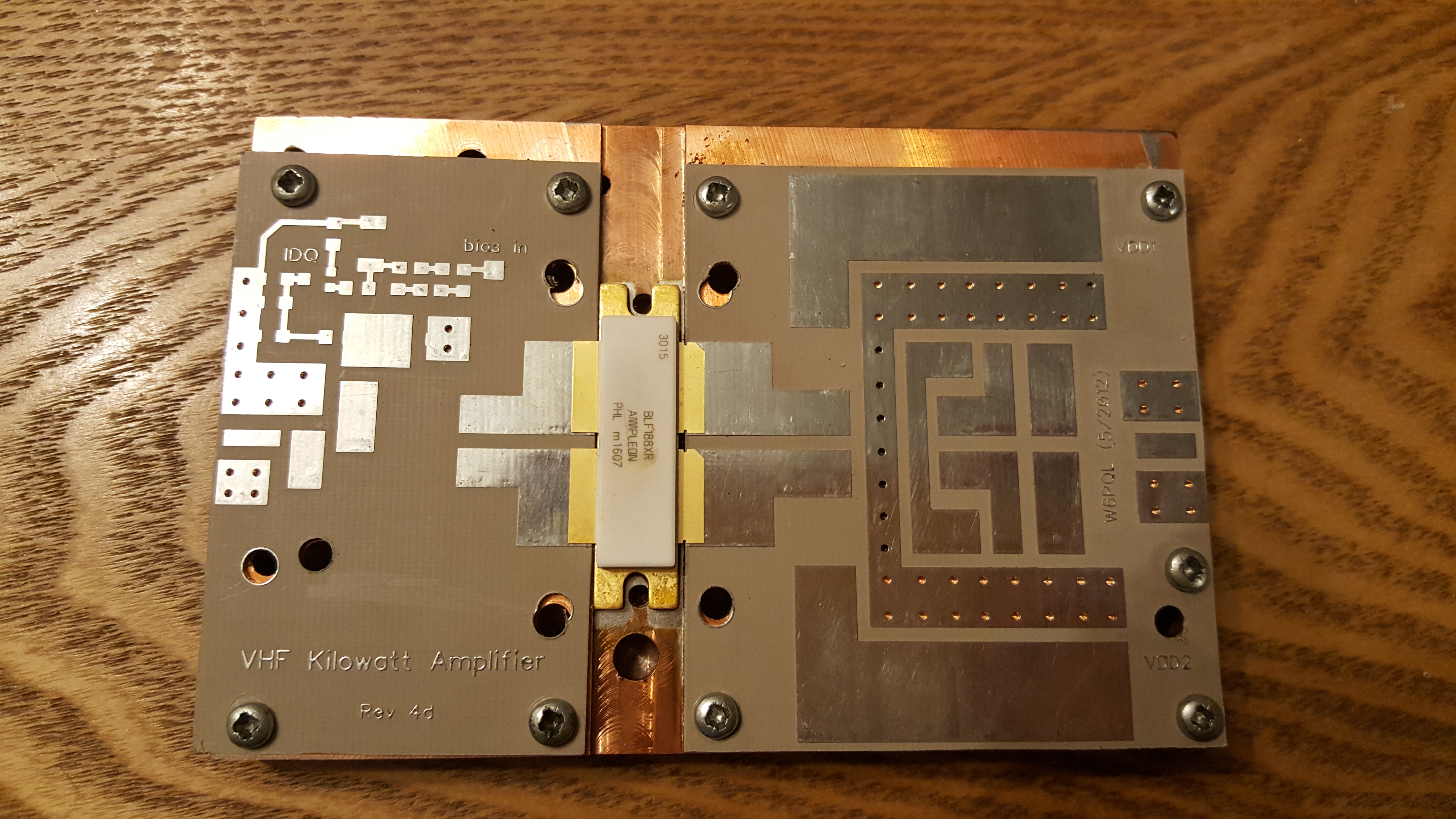
The PCBs were finally mounted as a test fit. I will populate the boards before mounting them. Unlike the original jrd1 boards, these PCBs do not need to be soldered down. This means the boards can be soldered up and then mounted.

Stay tuned for more updates…

Amateur Satellites & Dual-band Beams

Having attended a short talk by Steve M0SHQ at Essex Ham about operating Amateur Satellites, and seeing Steve work the ISS via APRS, I decided to have a go myself. I built the dual-band beam he recommended several times, but the design always measured up poorly. In the end I tweaked the design somewhat, and come up with something myself – it’s all credit to the original designer, I just optimised it with some antenna modelling software. Details on the antenna can be found here: Dual Band Satellite Yagi.

ircDDBGateway Basics

Over the past week or so, I have been playing around with DStarRepeater and ircDDBGateway to learn a bit about DSTAR repeaters, given the progress GB7KH‘s NoV is making. I have made a simplex hotspot with my FT817 and a soundcard interface, although I can see that there is certainly room for improvement. I have ordered a DVRPTR_V1 GMSK interface which has been dispatched so that will replace the soundcard, lowering the CPU load. I am to have the system set up on a Raspberry Pi 2 B, which was released yesterday (maybe today actually). I think I now understand how to tune up those Chinese notch filters, too.

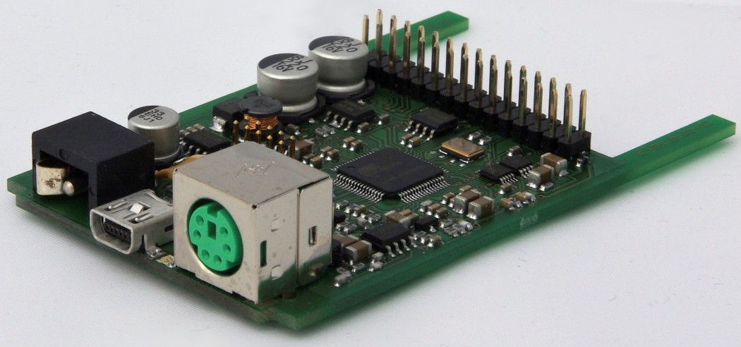
DVRPTR_V1 inside board