
At the beginning of May 2017, I decided to acquire a full set of W3NQN bandpass filters. Between members of the SNBCG radio club we had the odd filter, but I really wanted a set. Since I usually operate with Dave M0TAZ, real benefit would only be achieved if we both had a set of filters. I somehow managed to talk Dave into purchasing a filter kit with me, and then simultaneously let myself be talked into building it for him! This page documents the build process.
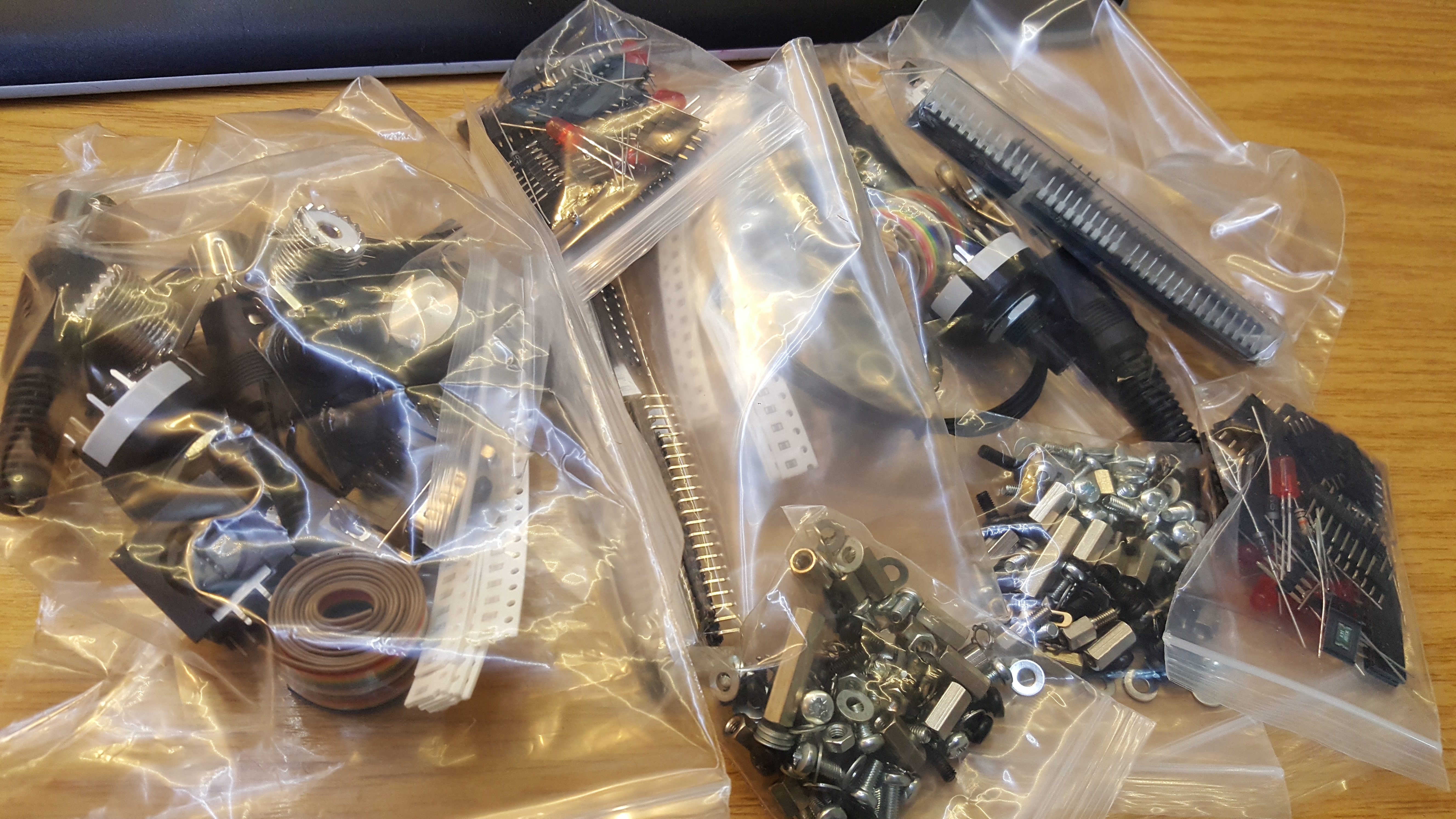
The project cost £321.27 each for the standard 6-band kits and included the toroids, capacitors from TabMica (now Charcroft), and cases. All I had to acquire was the toroid wire, 1.00 mm and 1.25 mm. I purchased 1kg of each, since others suggested they brought 500g for their kits, and I was building two. This will likely be too much, but it will get used in the future. 1kg of both wire diameters cost a further £18.70 per project, but, this should probably have been half, since I feel 500g of each diameter would have made both kits. The total cost for each kit here was £340, minus a few pence. Bob 5B4AGN was a pleasure to deal with, very helpful, and quick to respond to email questions.
So, where do I begin? First, with some useful links on the subject:
- TXBPF Yahoo! Group (sort of the project’s home page)
- Jeff AC0C construction notes
- Wires UK (retail Scientific Wire Company) – where I purchased the enamelled coil wire.
I found the build notes on the TXBPF Yahoo! Group (inside the files section), called “TXBPF Assembly & Alignment Manual”, and skimmed through. It all seemed logical enough, no real surprises. I had made single band versions of the W3NQN filters before, so I knew the actual tuning of the filters could be a bit tricky. For this reason, I decided to start with putting the other parts together; the band switching, etc. I started with the smaller boards, just to use up some of the bits.
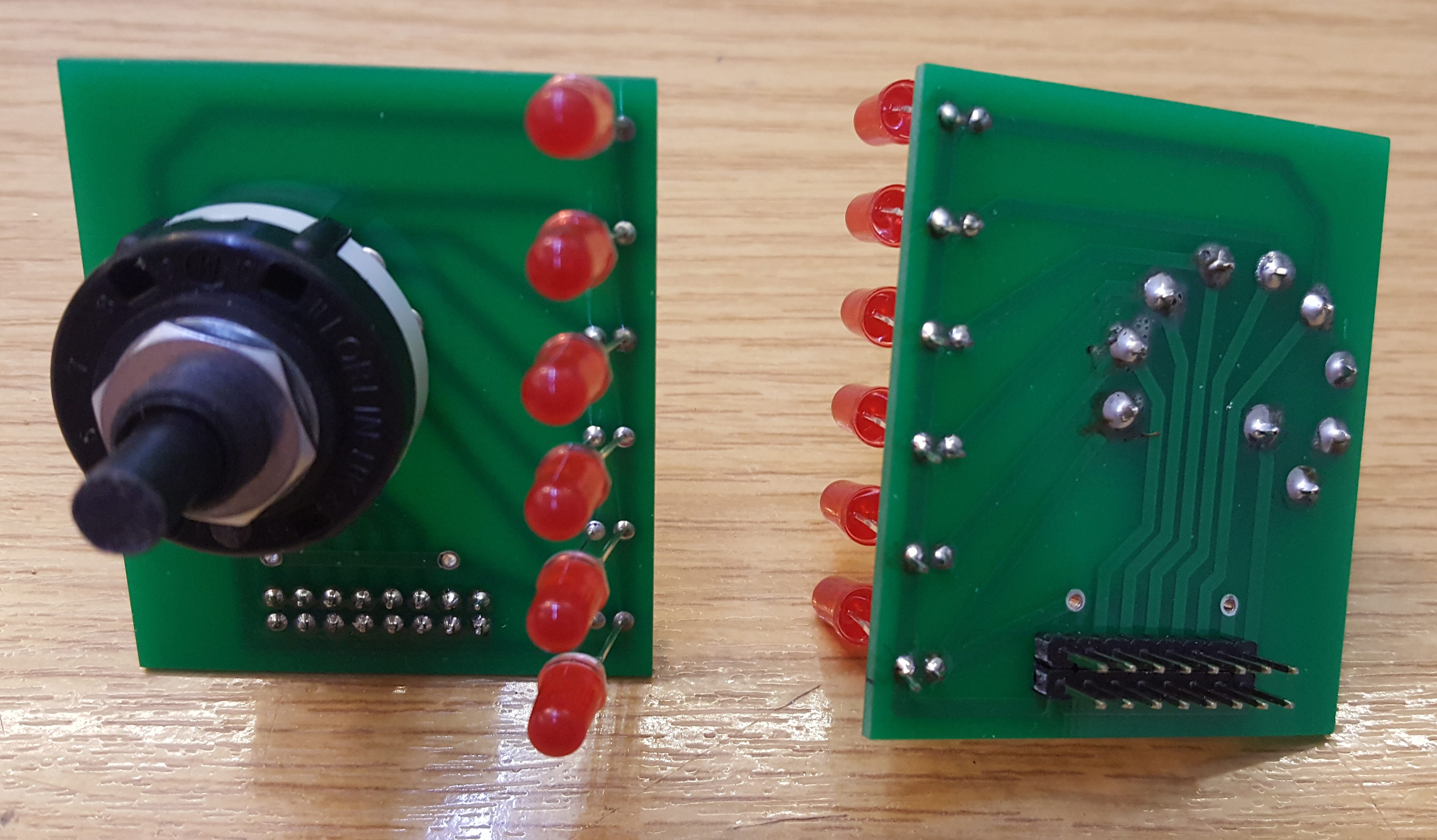
I firstly made the switch front panel with the 6 LEDs. I started by soldering the switch onto the board, followed by the 8-DIL pins. If you’re soldering 2×8-SIL (single in line), then you can use the connector to hold them square. Be quick, so you don’t melt the connector, and be careful not to squeeze the connector (thus crimping it to nothing).
I correctly orientated the 6 LEDs in the board (long legs are anodes, which are all common). Then, I bolted the switch to the front panel, and pushed the LEDs into the respective holes on the front panel, pushing them firmly to fit, and then soldered them in. These looked something like the image below, once removed. Note, I will flux clean all the PCBs before final assembly.
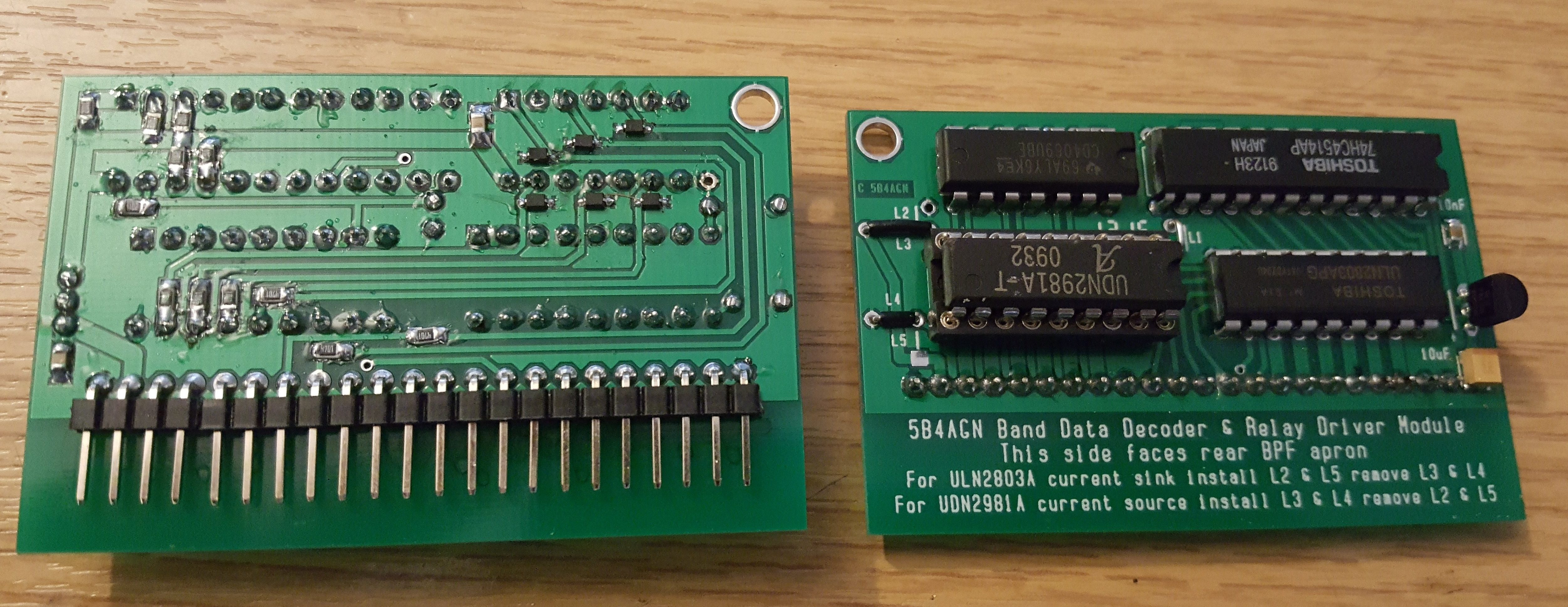
Next I went on to the band decoder. Following the build instructions, I started with the 6 4V7 SOD-323 Zener diode diodes. They are pretty small. I soldered these in carefully, observing the polarity. As an aside, I like to use my mobile phone camera, with about 8x magnification, to see the parts, and check any solder joints. USB microscope devices are also cheap and are also useful. Here’s an image from my phone camera:
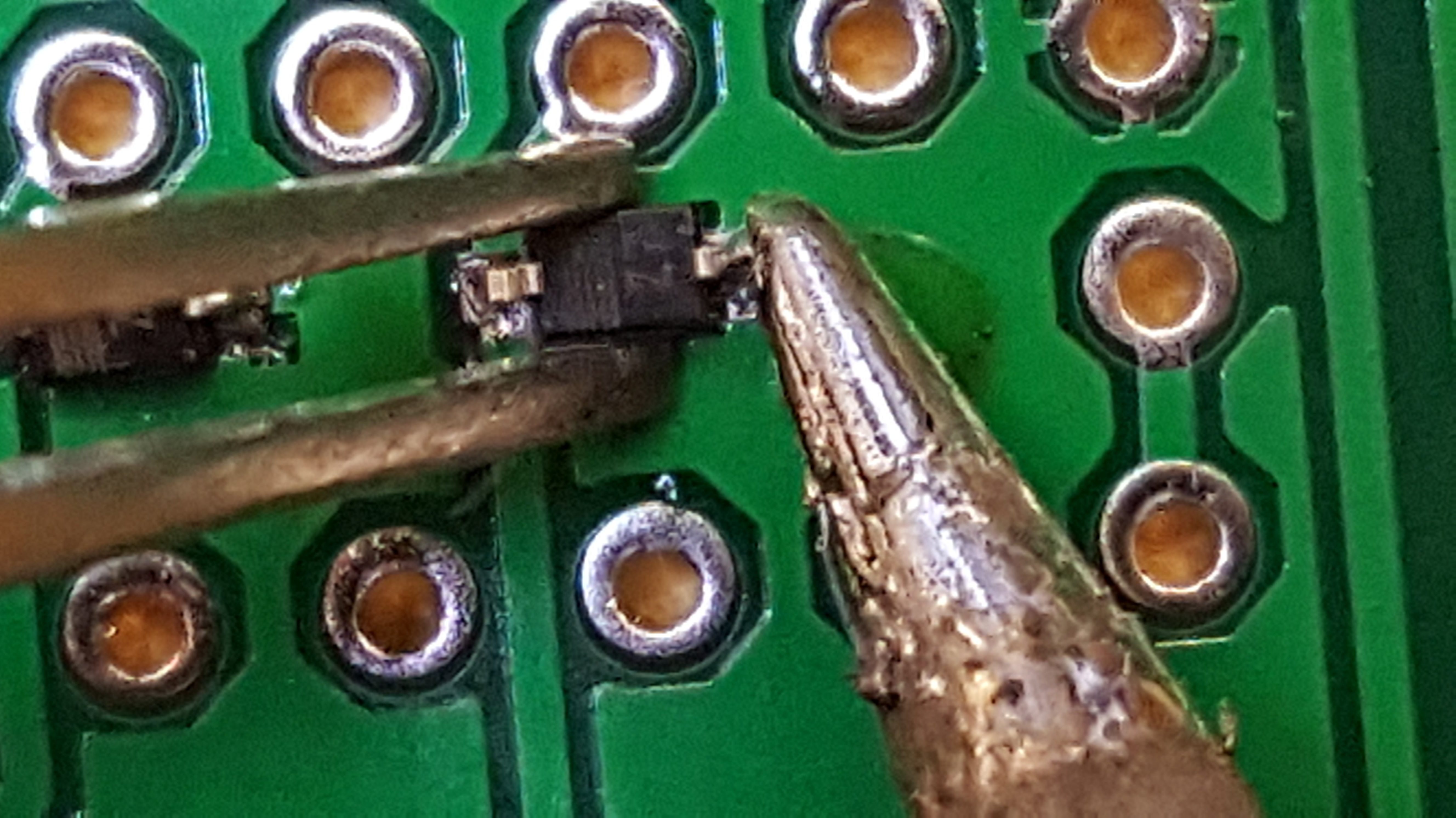
My general approach for soldering SMT parts is to tin one of the component pads with the iron. Then, heating the small ‘puddle’ of solder, I slide the part into the pool, being careful of the alignment. I then remove the iron, and allow the joint to cool – I’m not concerned if the joint is poor at this stage, I just want it to hold the part in the correct place, so I can solder the other leg. Once the second leg is nicely soldered, I reflow the first, ensuring the joint is of good quality.
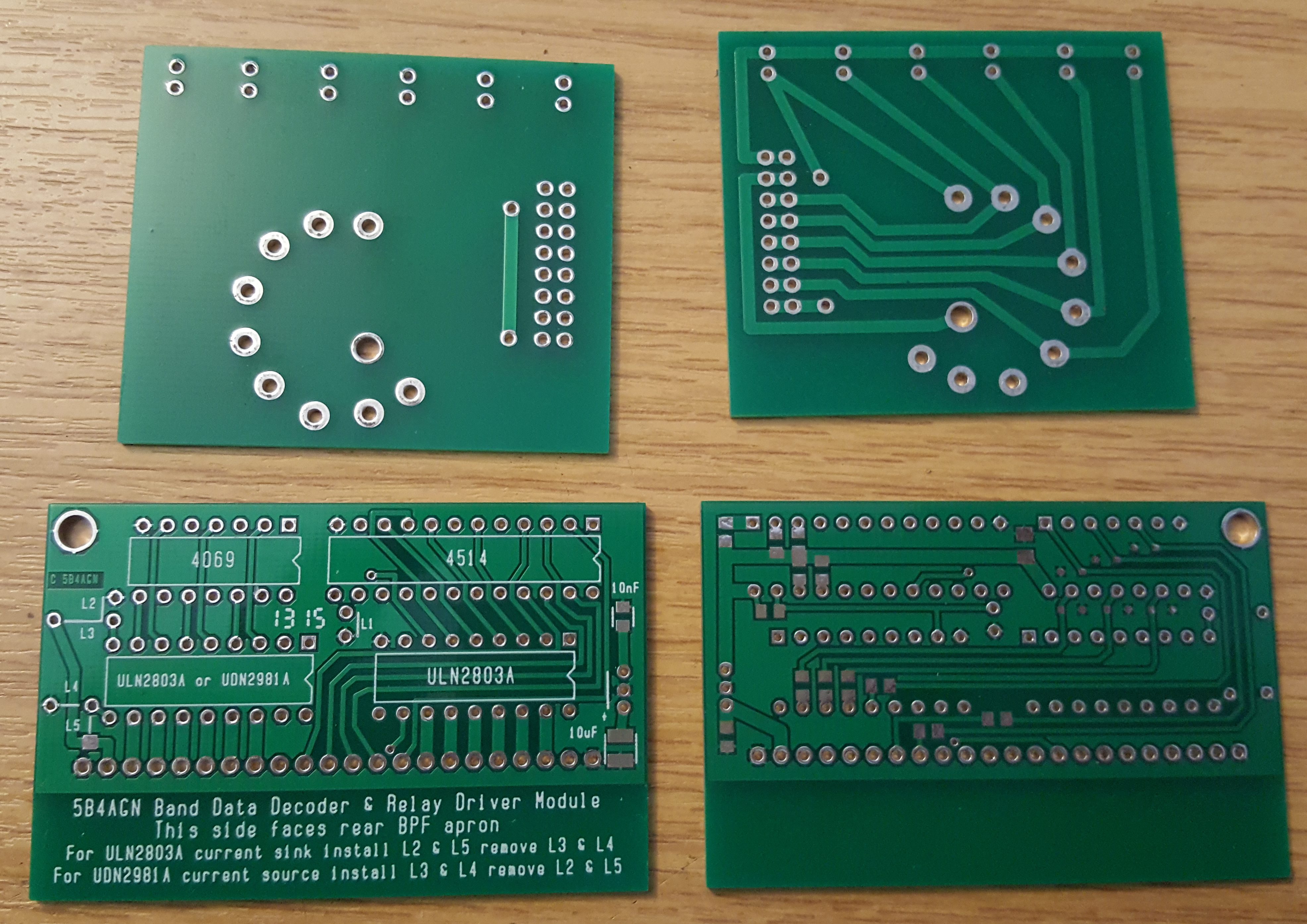
The band decoder boards, finished:
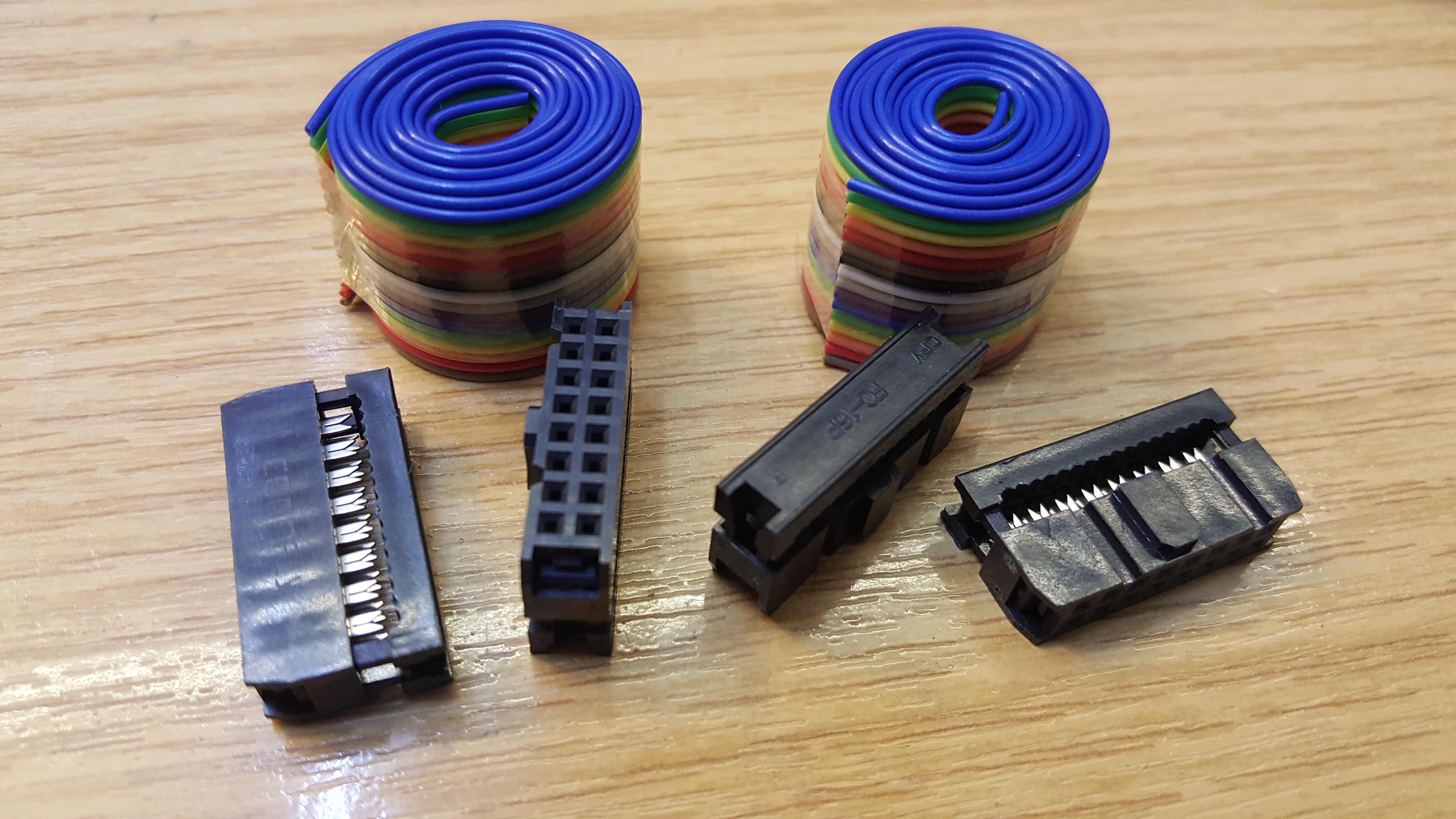
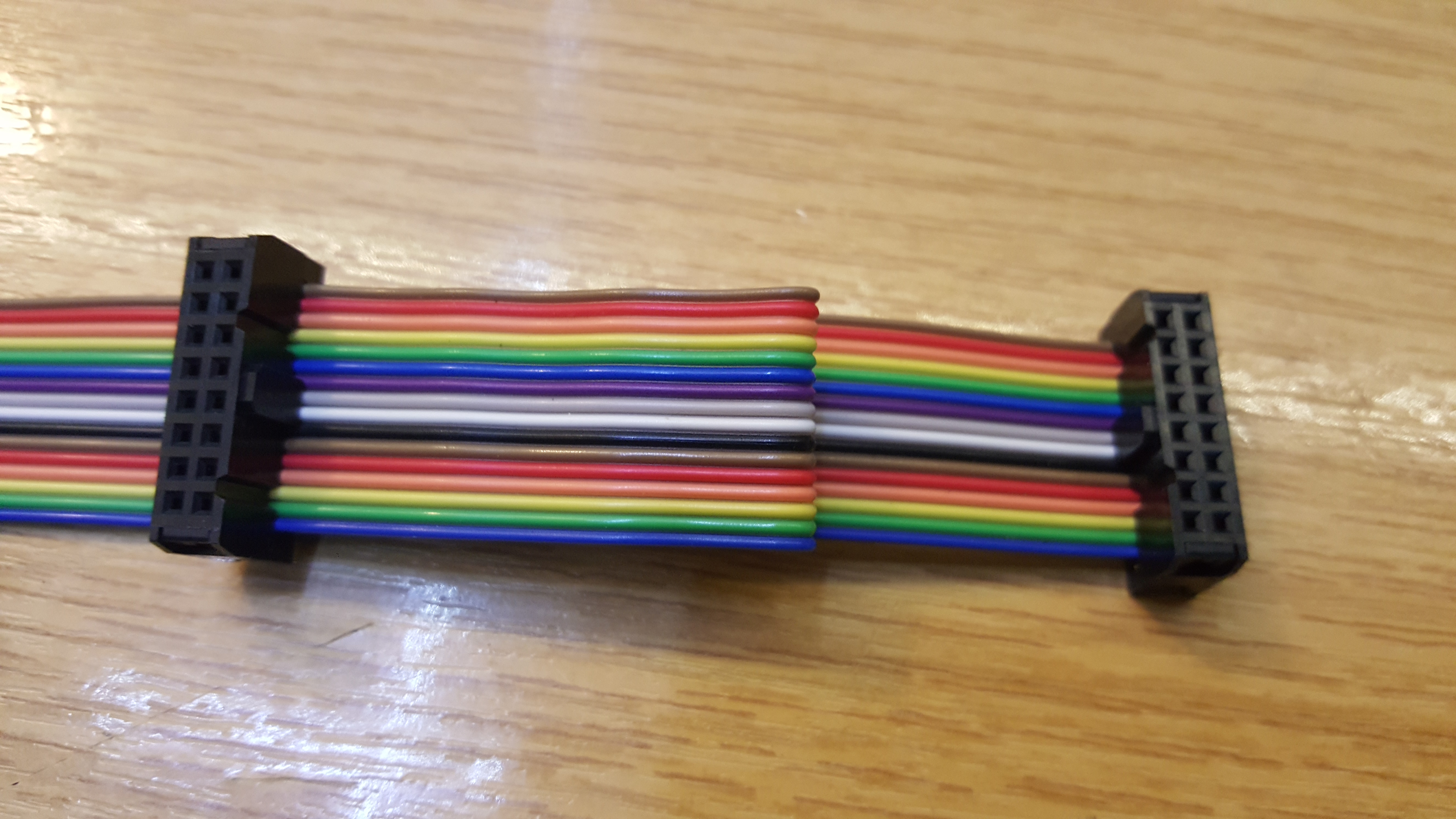
Next I made up the cables for the front switch. Following the build instructions, a length of 500 mm of ribbon cable was needed. The connector orientation tabs face each other on the same side of the flat cable. Care must be taken to ensure the cable fits correctly into the crimp-connector. Failure to do so will result in shorted pairs of wiring, or skewed connections. My attempt went well. In the below-right picture, the connectors are on each end of the cable, but the length is folded back to show the orientation of the connectors.
 |
 |
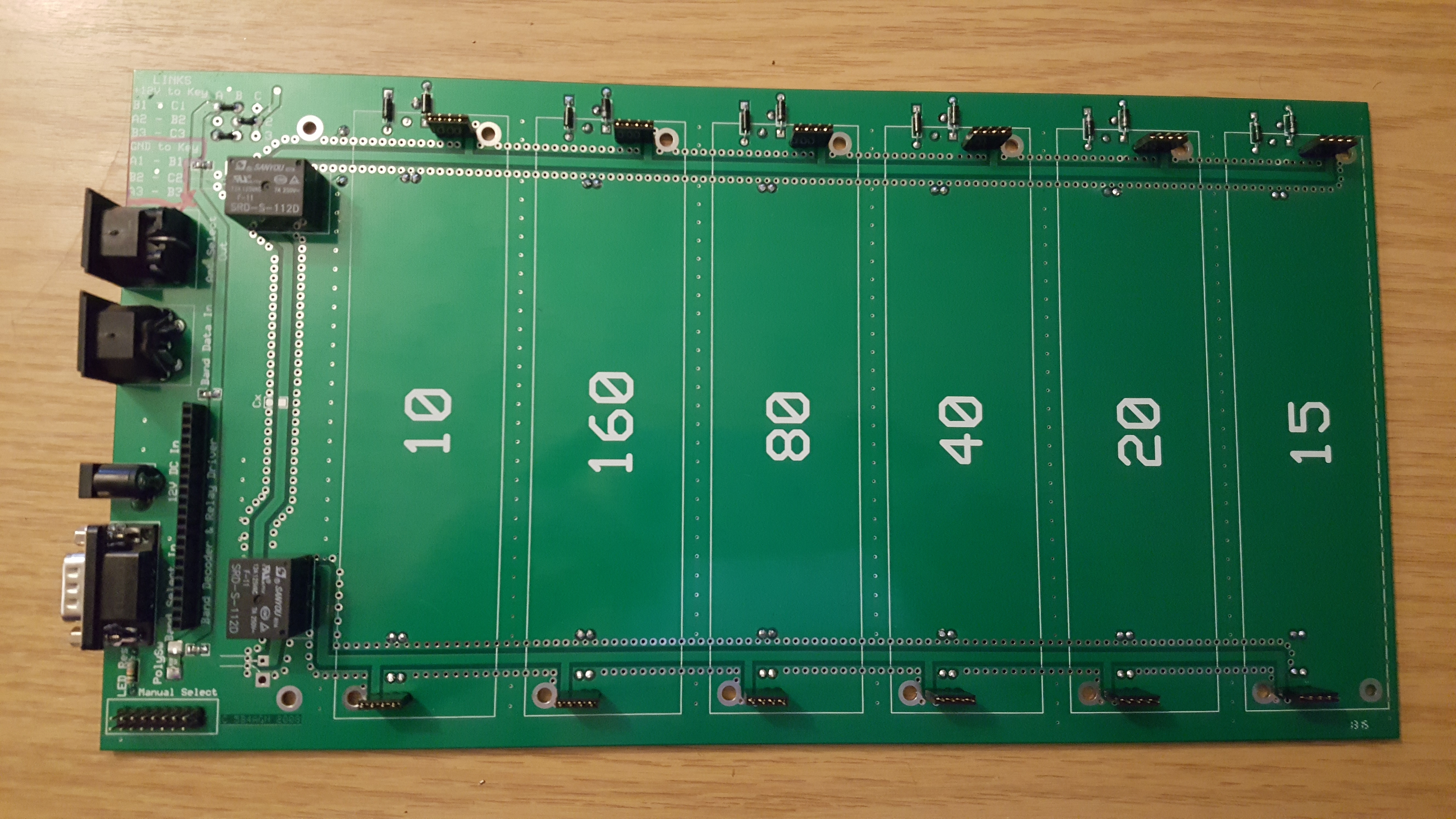
The final part of this stage was to build the large main-board.
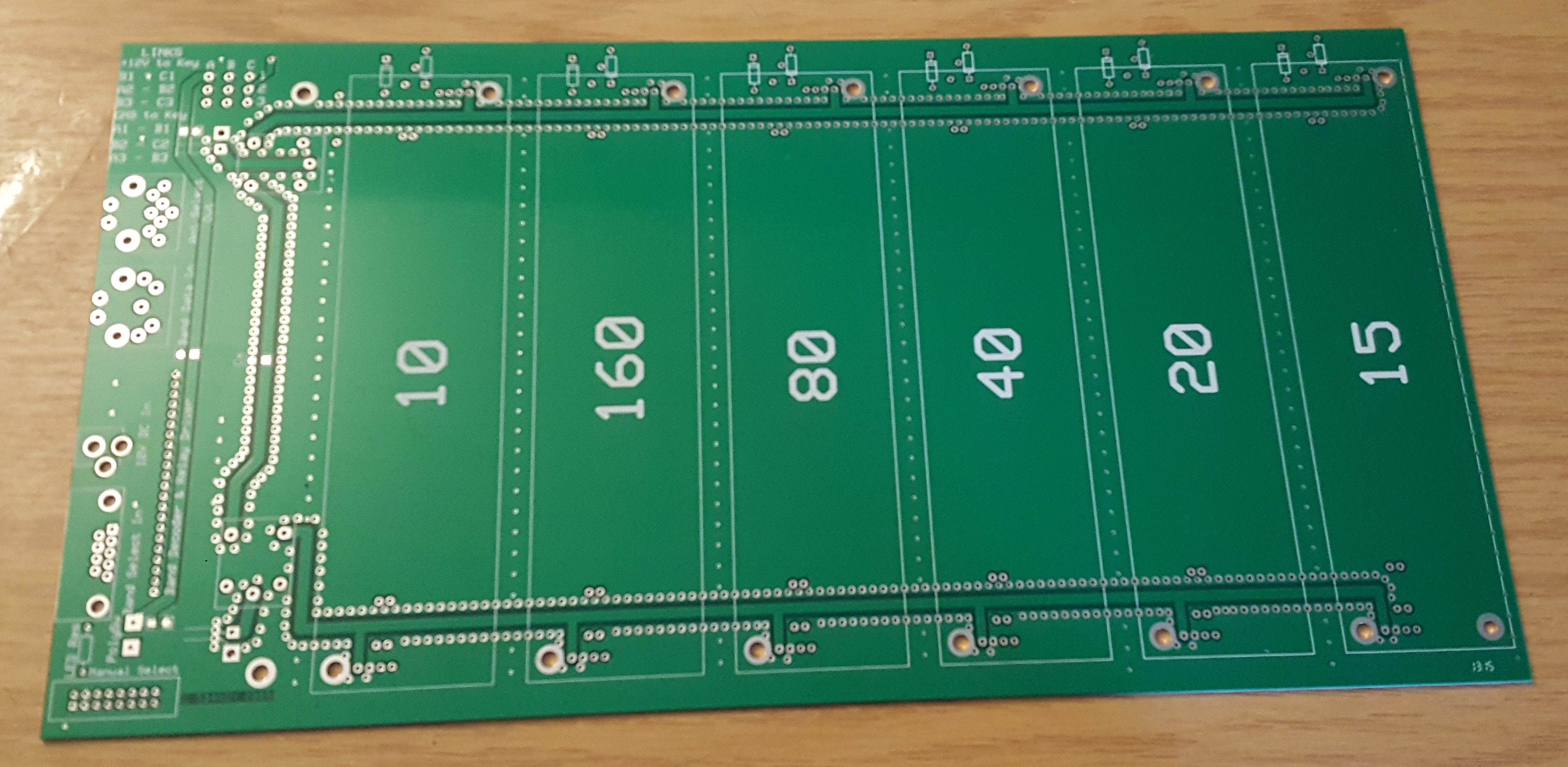
This took a while to build, since there a large number of 100nF decoupling capacitors, as well as wire links which needed to be cut to length. The board material is heavy with a large copper fill, so you will need a high power soldering iron to solder some of the ground connections. After soldering the decoupling capacitors and links, I soldered on the connectors and header pins as recommended by the build notes.
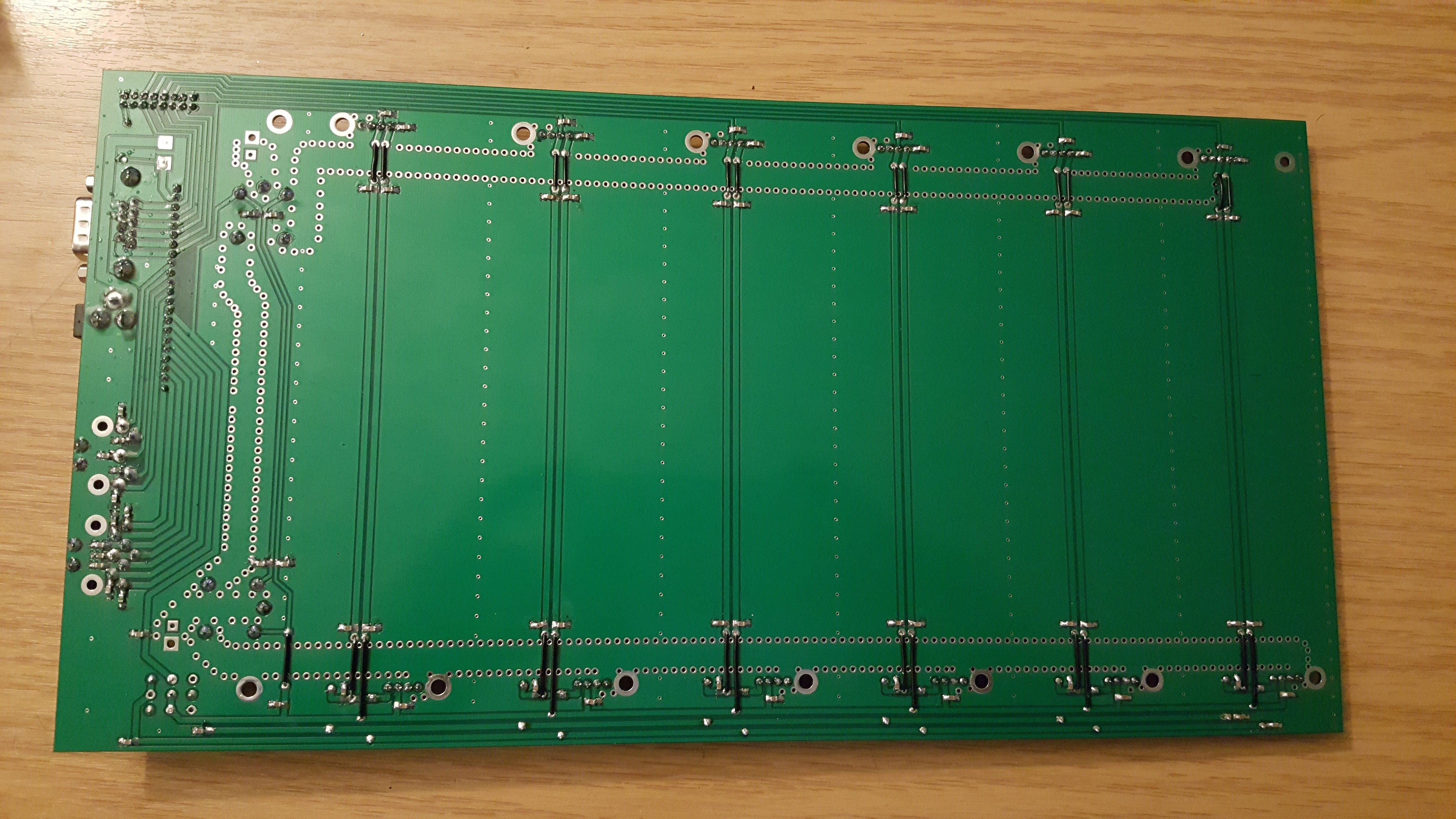
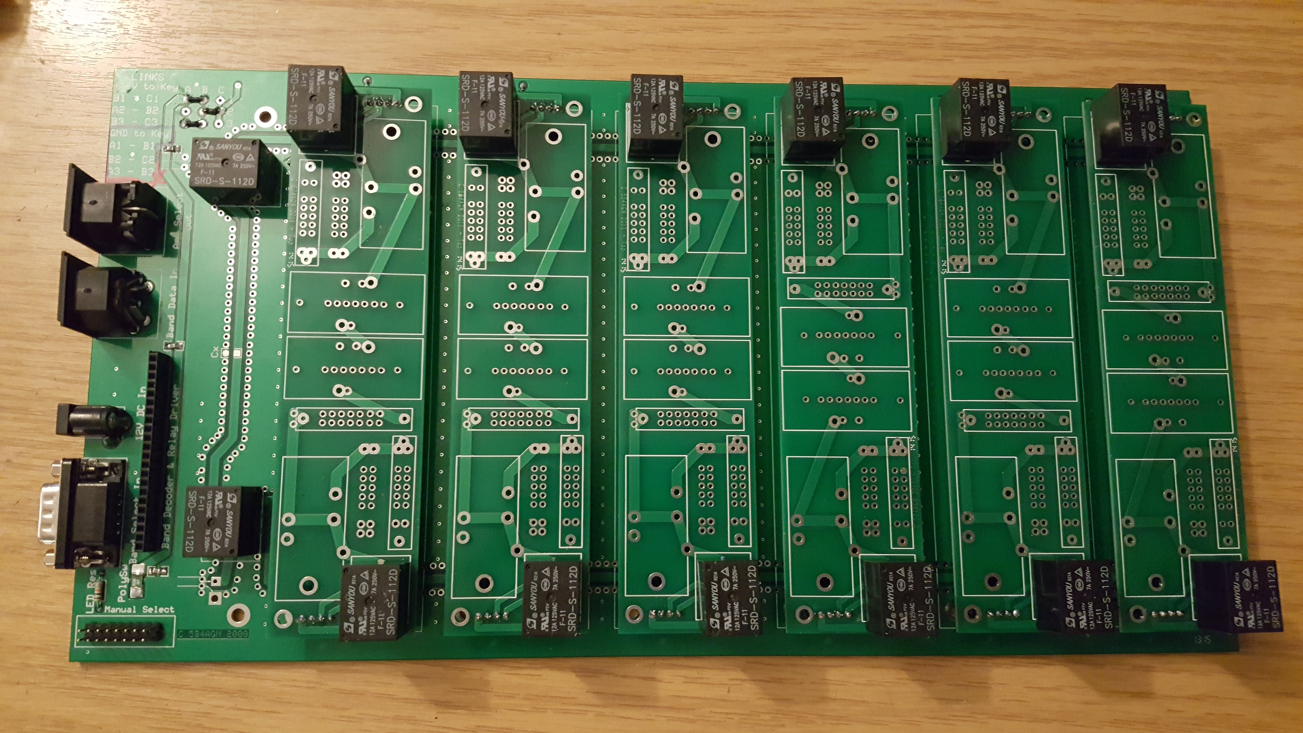
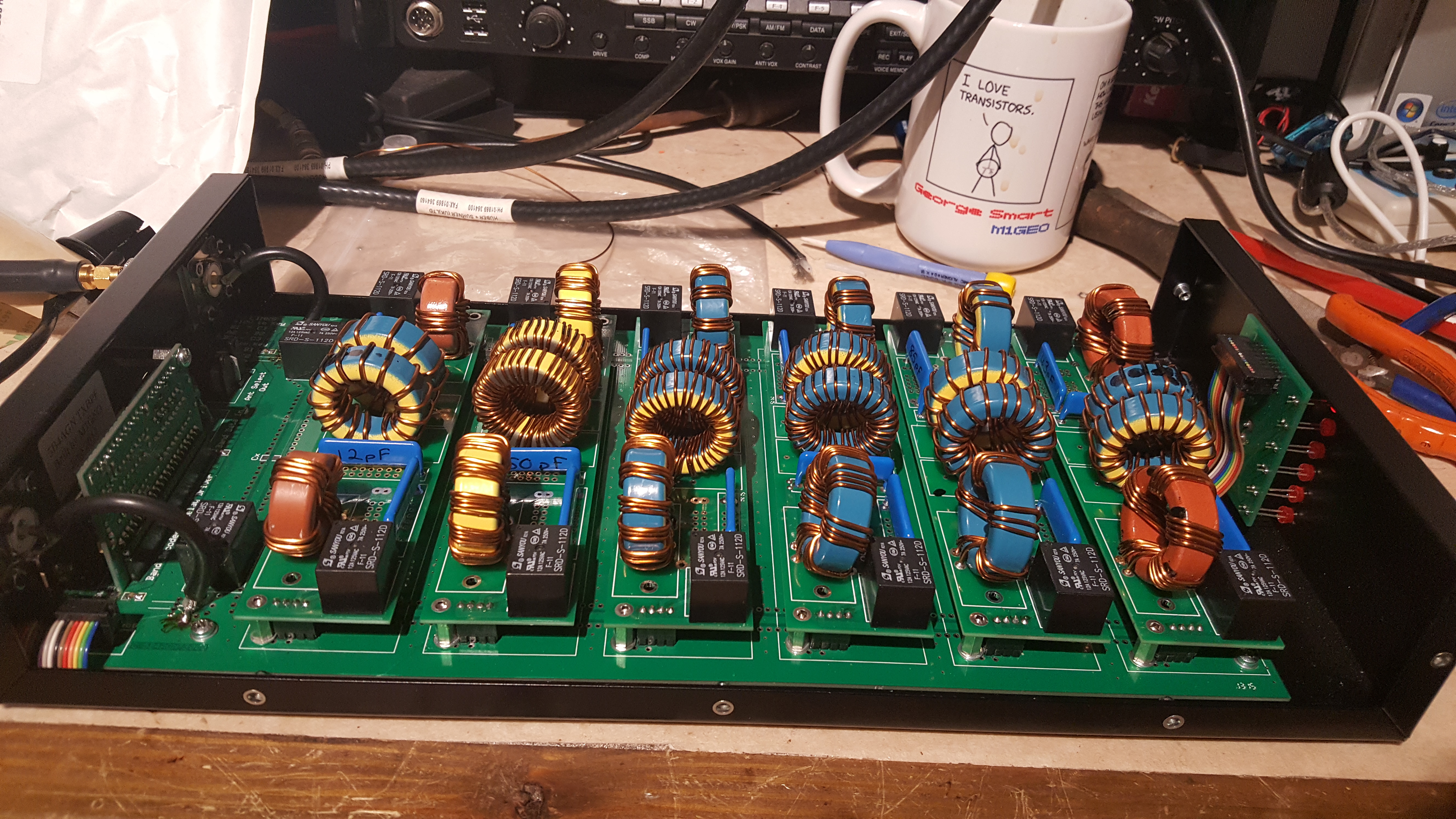
Finally the remainder of the decoupling capacitors were soldered to the underside of the individual filter strips, and the board interconnects were soldered as recommended (SIL4 male to the mainboard, 4SIL female to the filter board). The relays were fitted, 2 on each of the 6 filter boards, as well as 2 on the mainboard for the bypass path.
All that remains now is the long task of building the actual filters!
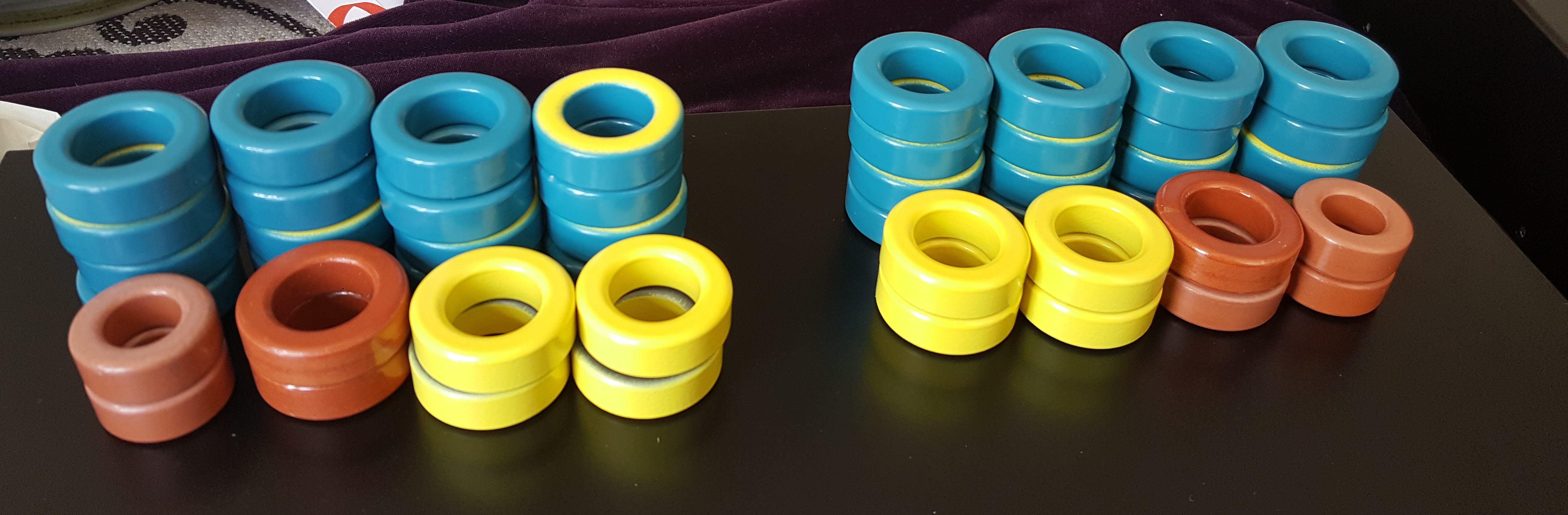 I managed to persuade Chris G8OCV to wind the toroids for me while I was at work. Chris wound the toroids according to Bob 5B4AGN build notes, winding the turns tightly to the core. In every case, the extra turn was added which could be removed after. Generally, the extra turn was needed. In some cases it was removed. The 80 metre series inductor needed two extra turns.
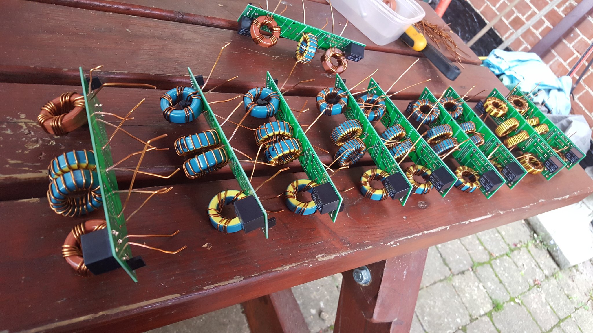
Over the course of the following few days, Chris and I went through the filters, soldering the inductors and capacitors to the PCBs. This itself was no mean feat, since the inductors are quite heavy wire and need pulling around to tune. Once the inductors were tuned, a small amount of epoxy resin was added to secure the toroids and to hold the windings with the correct spacing. We finally ended up with the following, complete with desk junk!
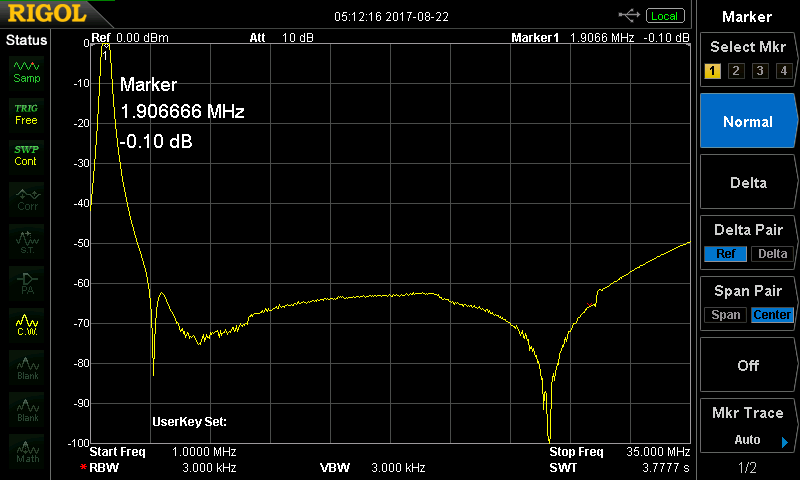
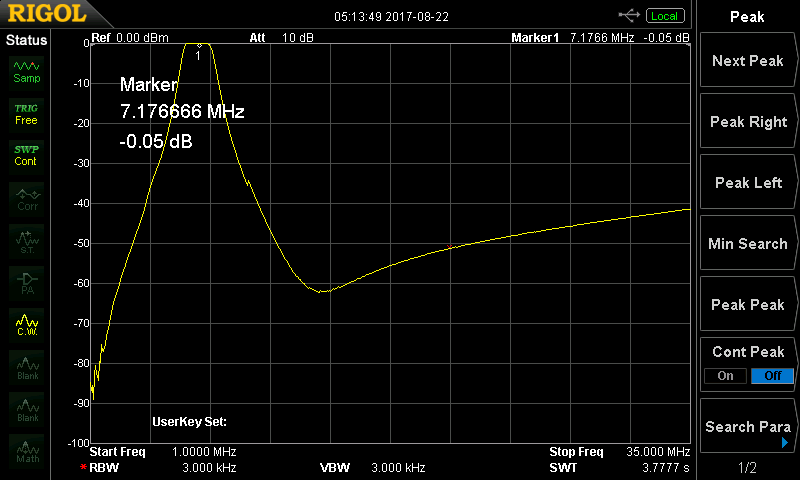
 After everything was assembled, soldered down and affixed, we re-swept the filters to graph their final responses. These are presented below for each band on the same scale. The marker shows the insertion loss through the entire filter, socket to socket.
160m:
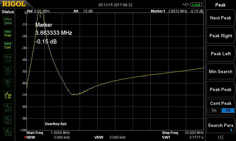
 80m:
80m:
40m:
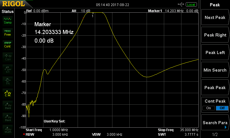
20m:
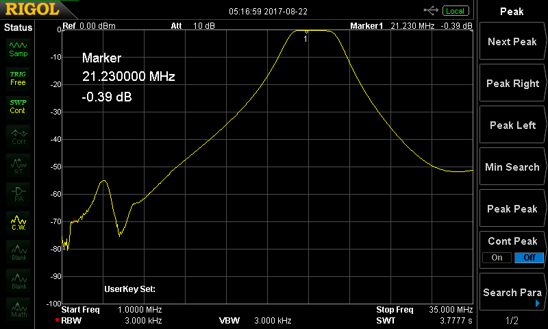
15m:
10m:
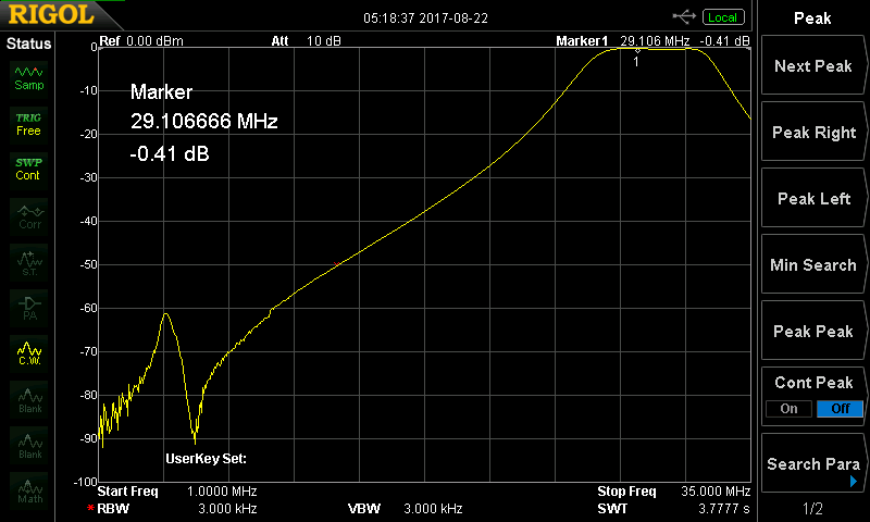
With a little more patience, I think I could have gotten the filters slightly better, but, I’m sure they’re acceptable for now!