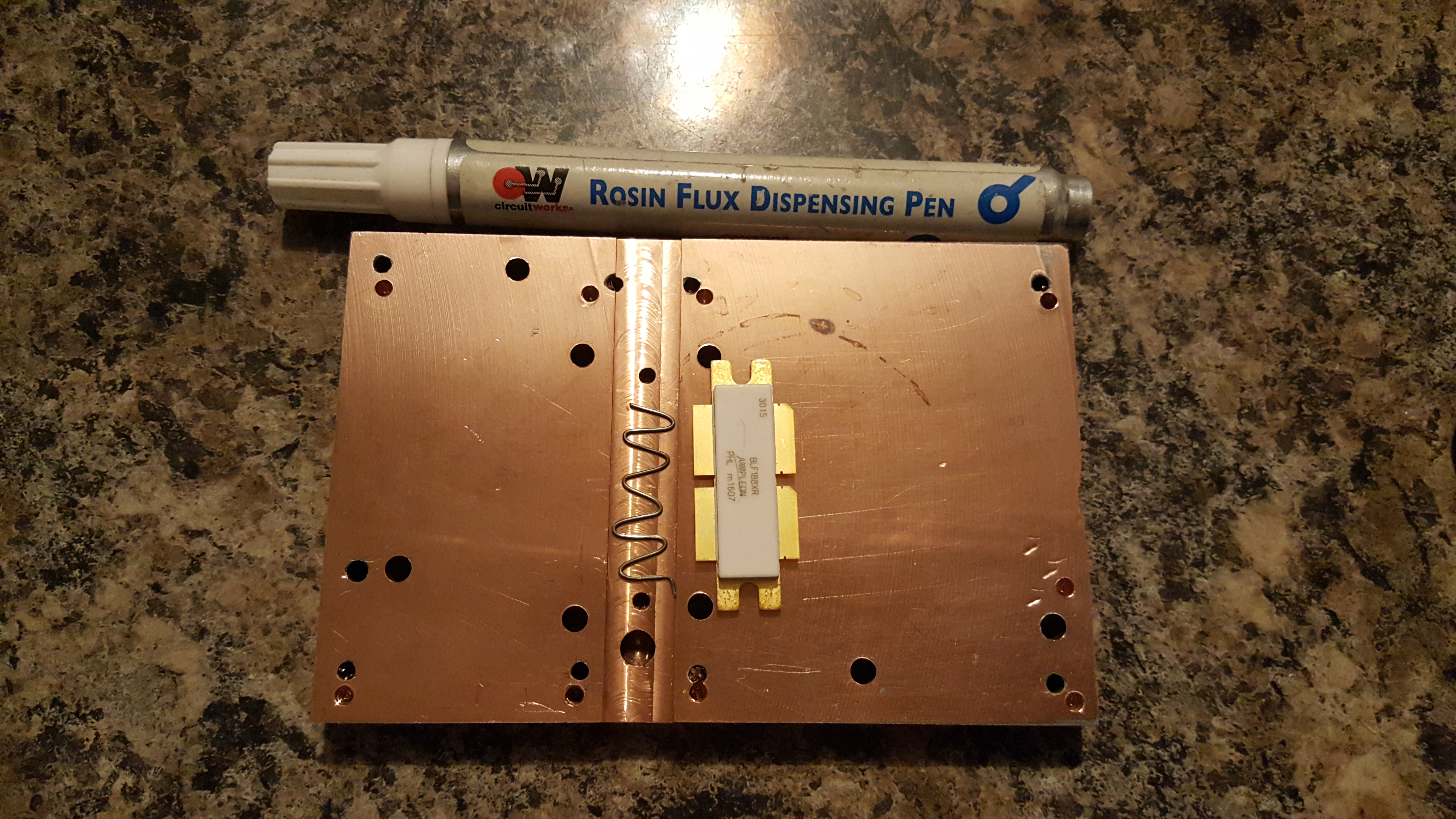
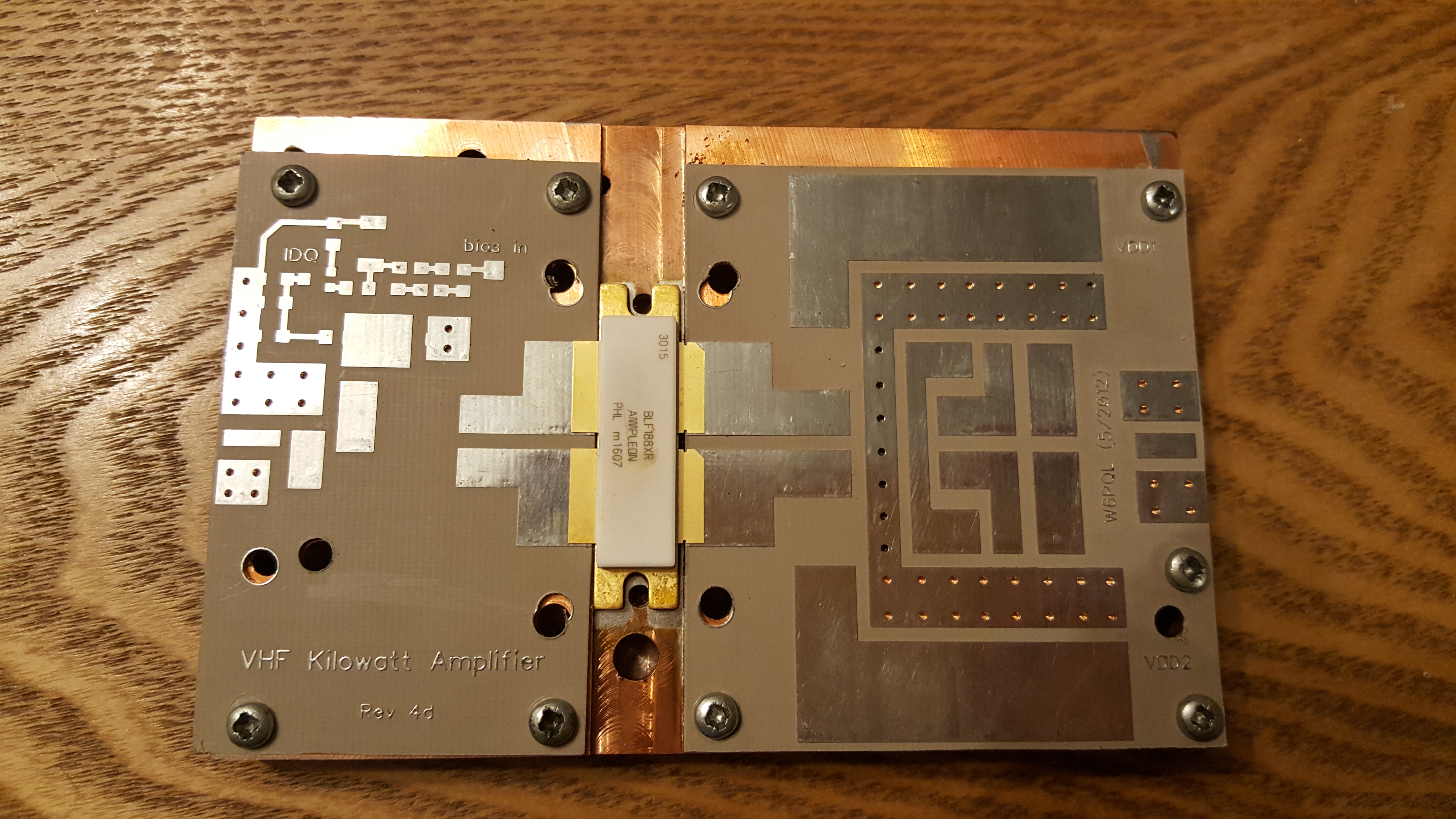
Back at the 2012 Friedrichshafen Hamfest I brought a 1.25 kiloWatt VHF amplifier kit for 144 MHz from F1JRD and F5CYS. These devices were fairly new at the time. It took me a year to pluck up the courage to build the pallet, but I went about it all wrong. With the help of Dad and the kitchen hob, we soldered the jrd1 Teflon PCB to the C110 copper heat-spreader as suggested in the Dubus article (see here). I had the pallet working at the time, giving around 600W of RF, which was about the maximum my 1000W 50V PSU was capable of sustaining. When I came to boxing the device up into an amplifier to use with EME and Meteor Scatter in late 2016, the part failed under test.
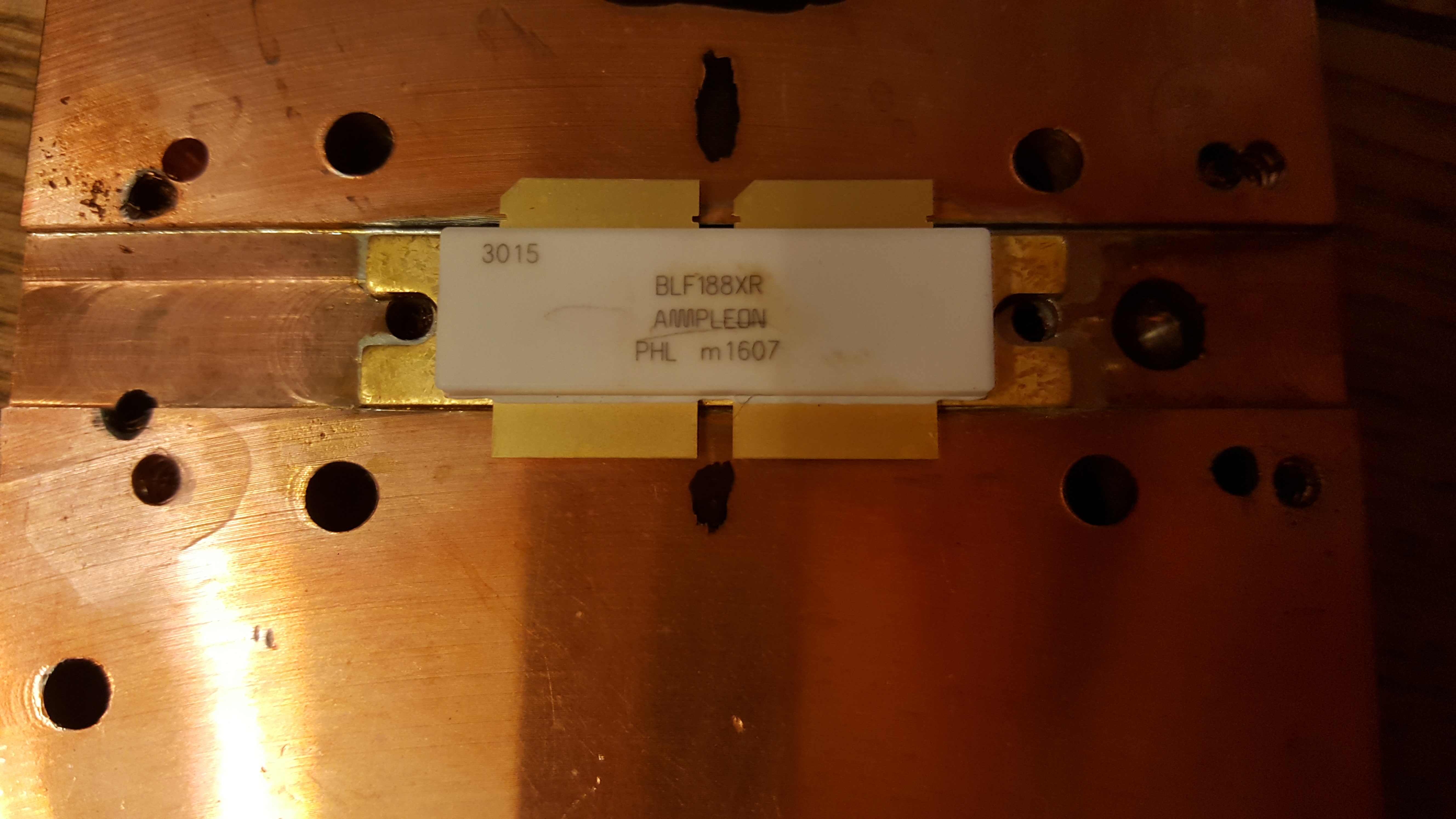
After much deliberation, I have ordered parts to repair the amplifier project. I found Jim W6PQL‘s website (see here) a wealth of information, and Jim also offers to supply parts and designs to help others. I ordered a set of PCBs to replace the original jrd1 board, a NXP/Ampleon BLF188XR 1400W part to replace the failed the Freescale/NXP MRFE6VP61K25H 1250W part, and some other accessories that Jim sells. The parts were posted by Jim today, so I decided it was time to recover parts from the old PCB and recondition the heatsink and heat-spreader.
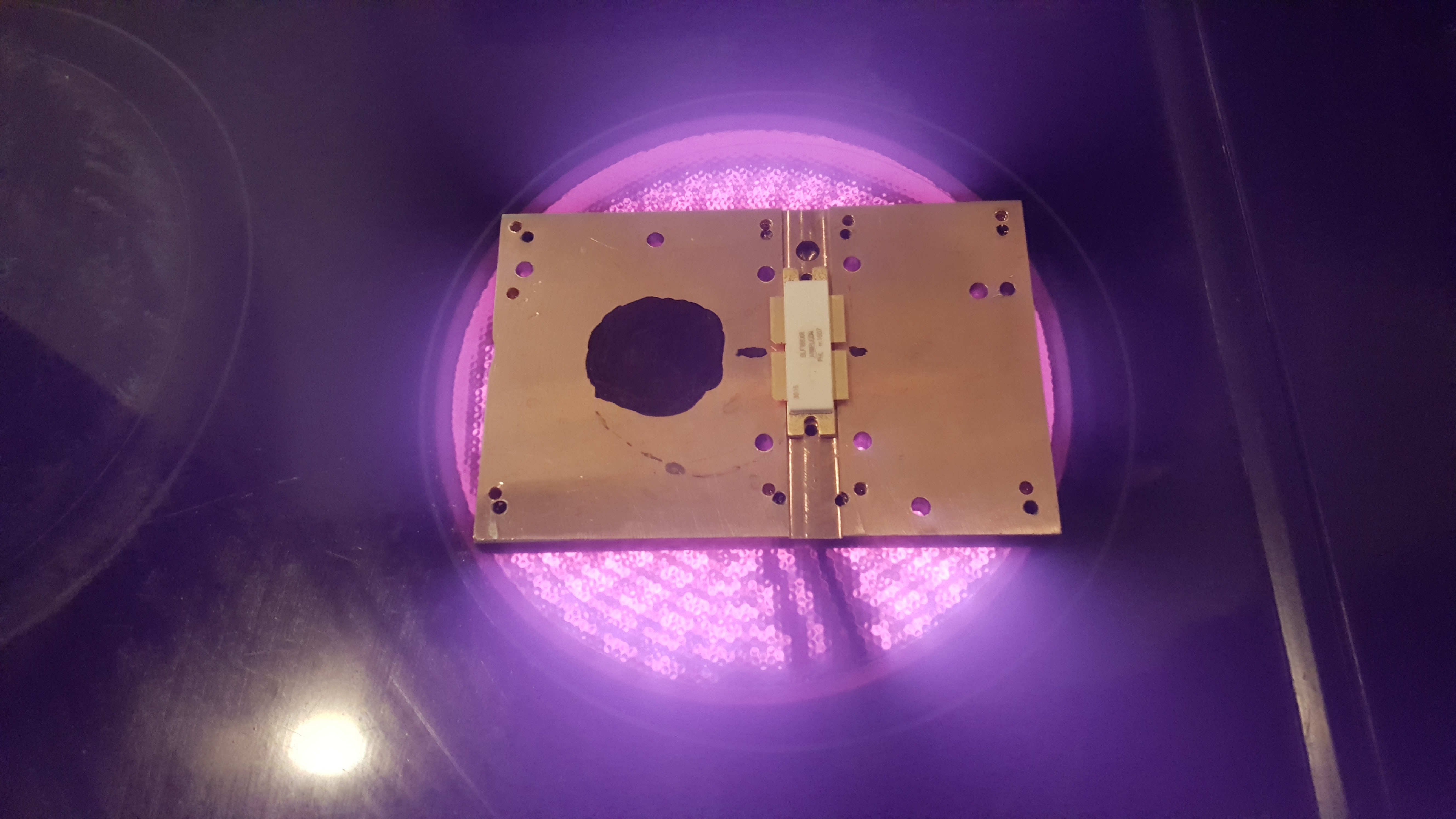
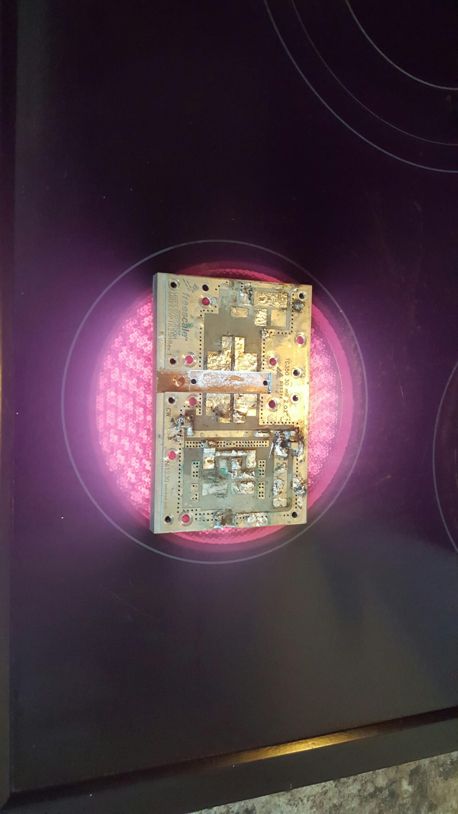
The first step was to remove the jrd1 board from the copper heat-spreader. I used the kitchen hob to heat the copper heat-spreader, since the old board was soldered to the copper block. The board damage was sustained to enable the removal of the more expensive components.
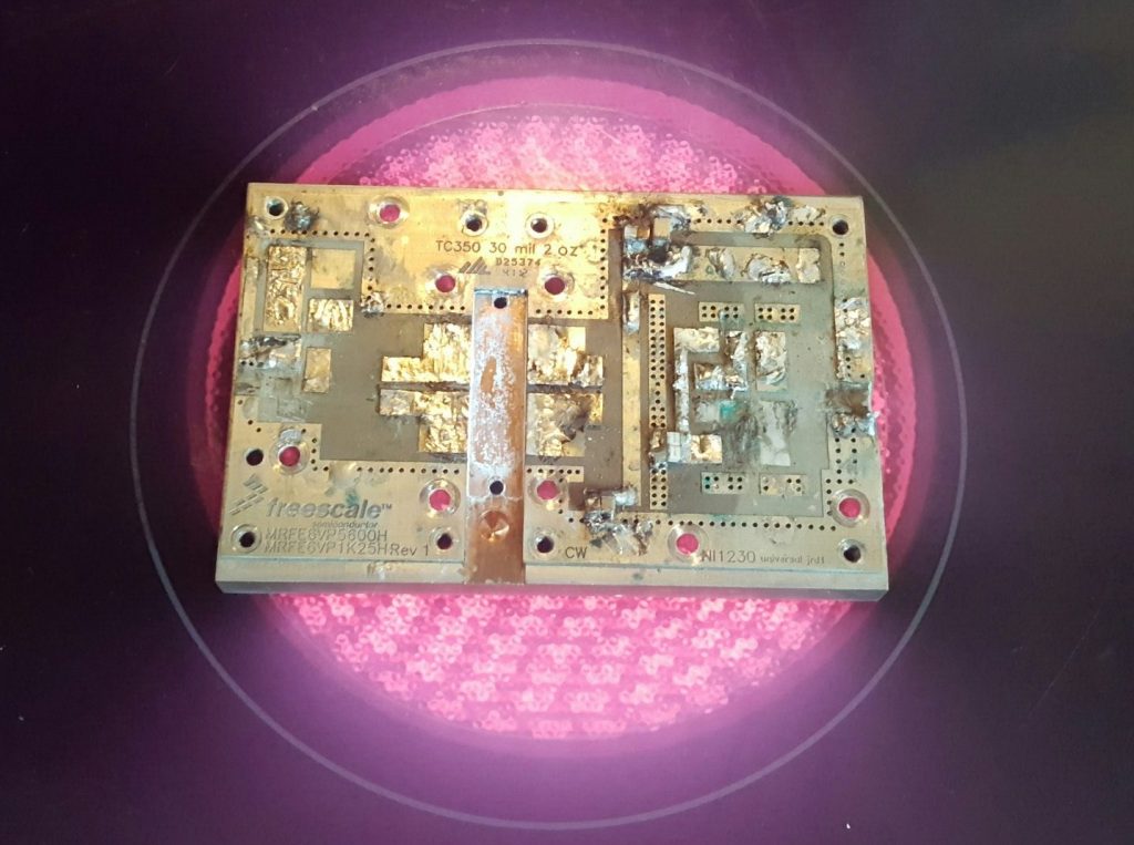
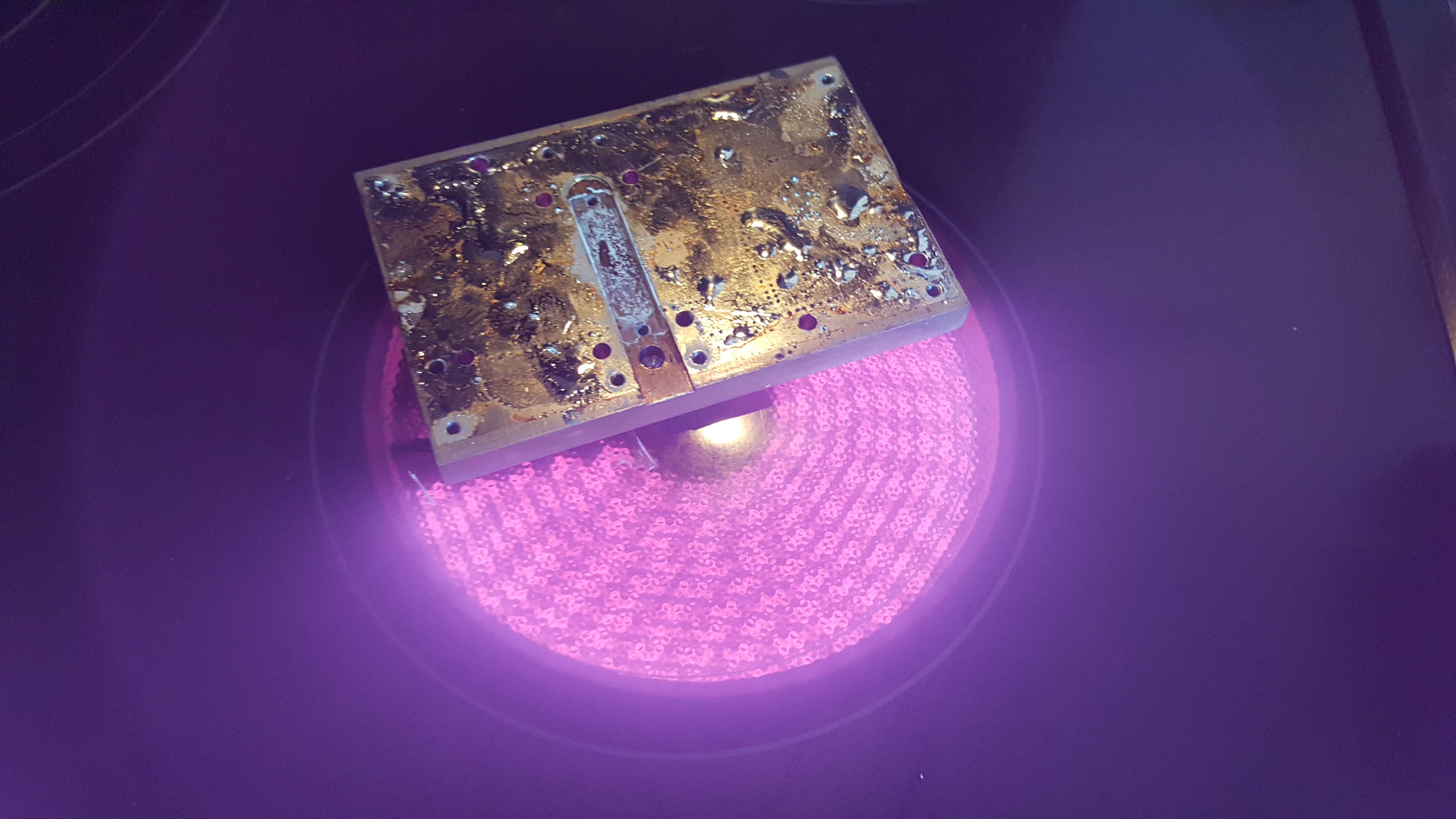
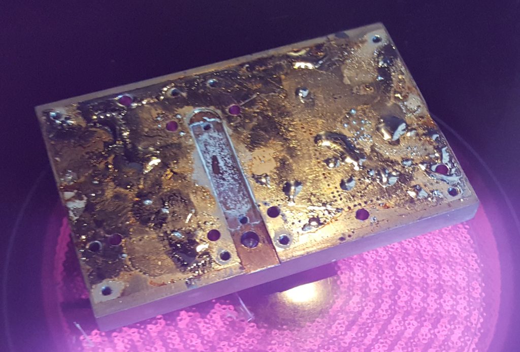
Below, the heat-spreader with the jrd1 board removed. I used a solder sucker and scraper to remove as much of the molten solder.
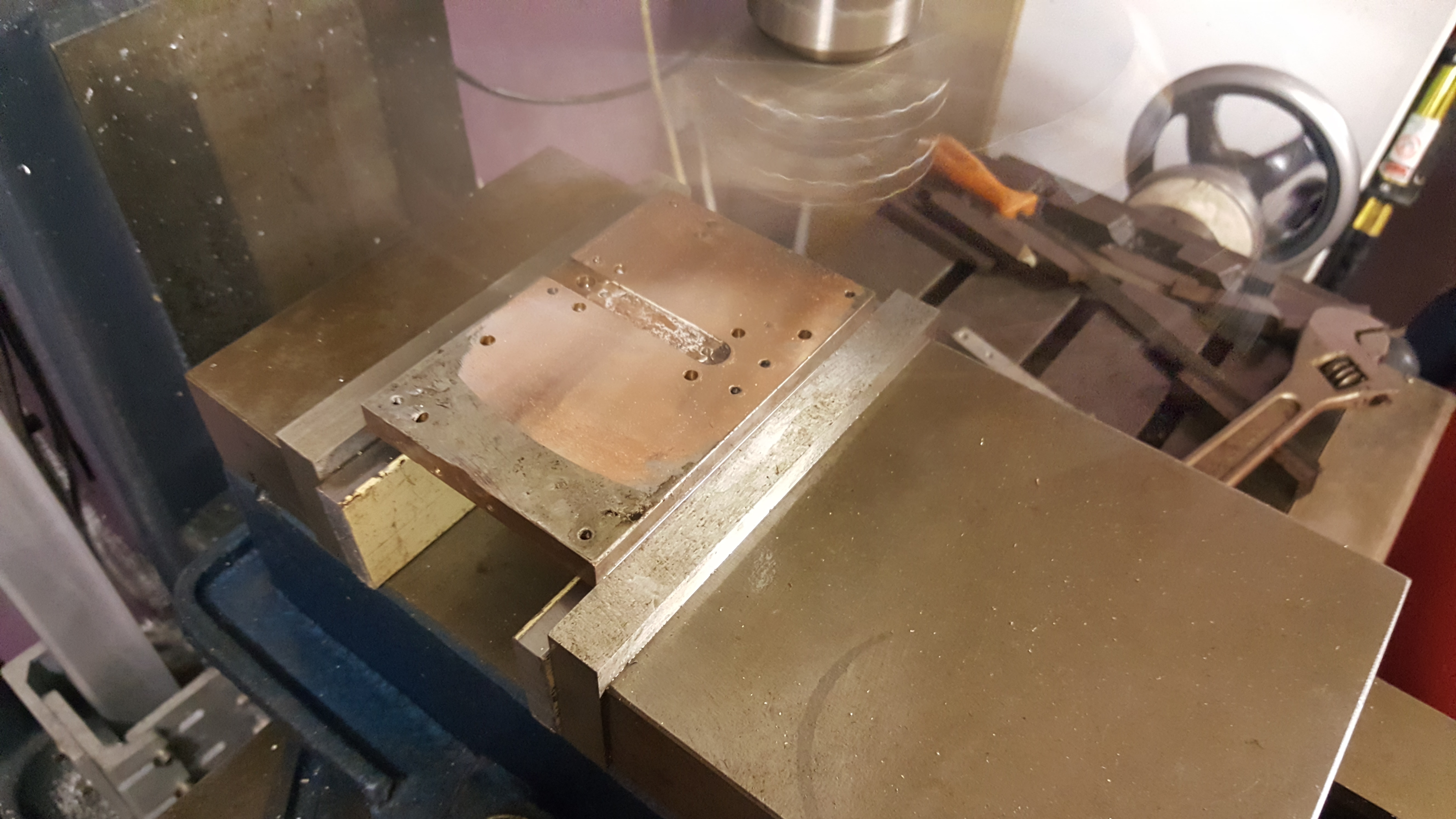
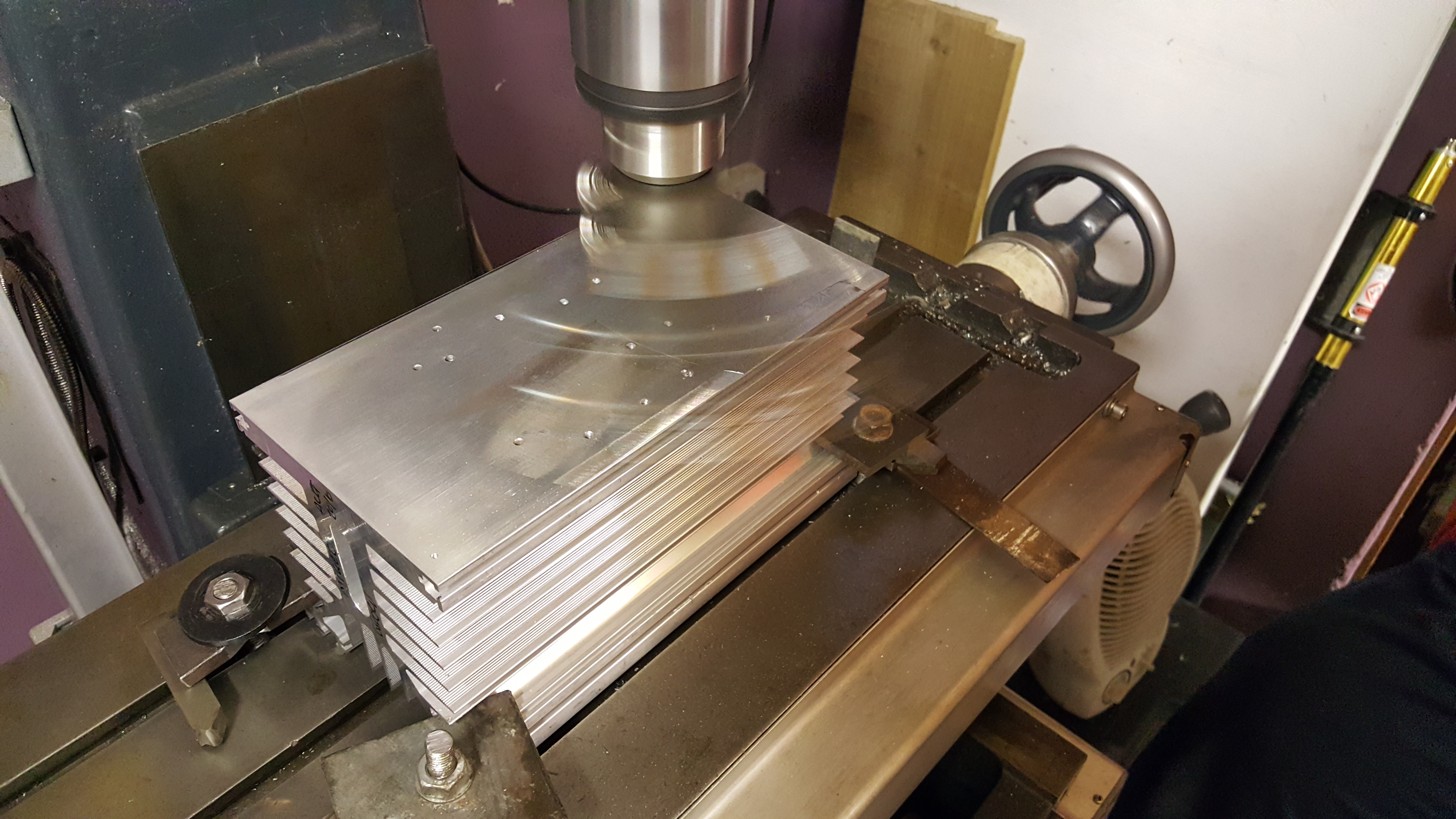
Once the heat-spreader had cooled down, I mounted the copper spreader up in the milling machine read to re-machine the top and bottom surfaces. Great care was taken to level the block using parallels. Below you can see the fly-cutting process on the first cut, removing just 0.05mm from the surface.

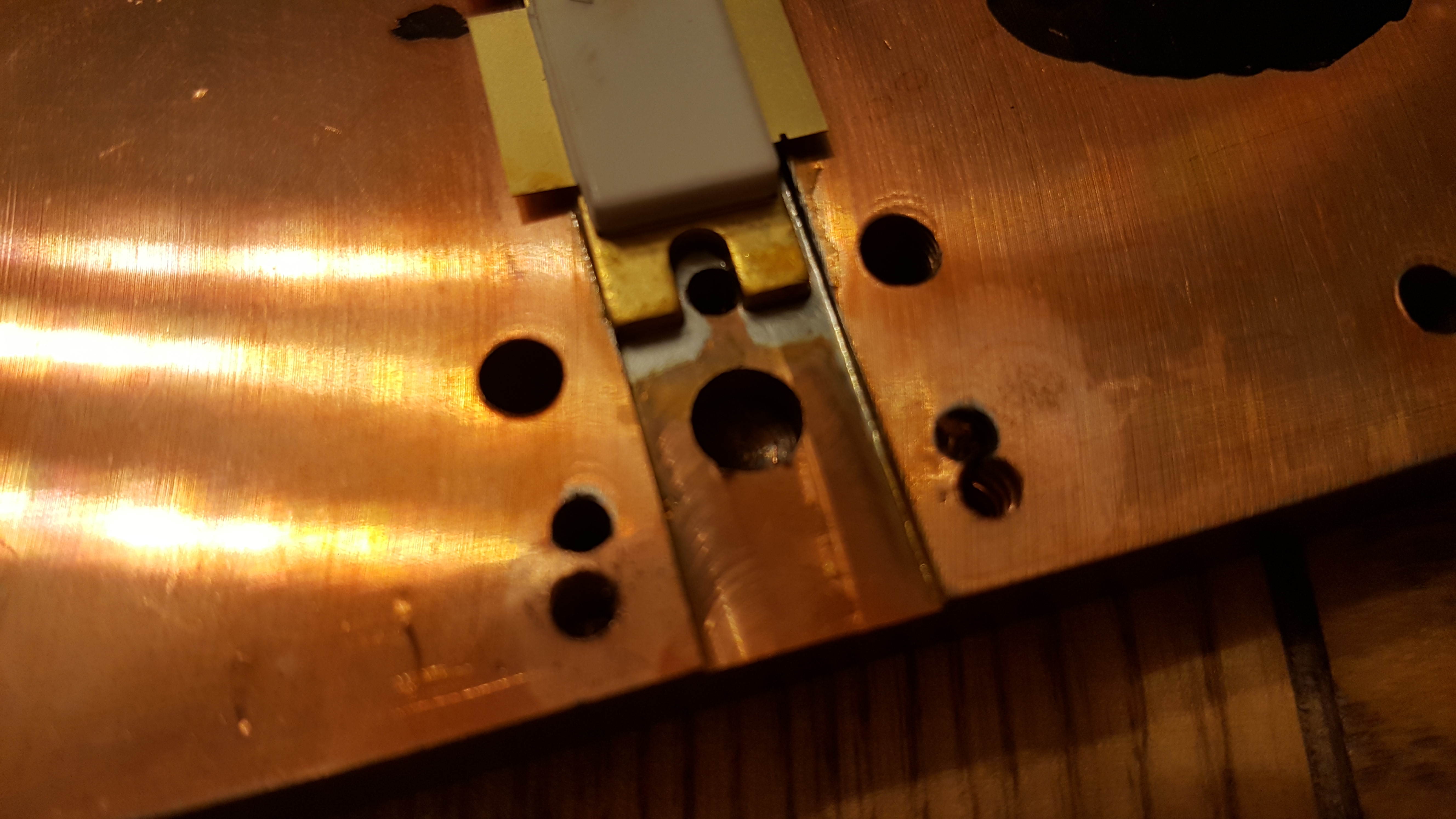
With the top and bottom of the head-spreader machined flat, a small end-mill cutter was used to machine the transistor slot to the correct depth following the skimming of the top surface. Then the heatsink mating surface was machined. Below you see the first cut on the heatsink.

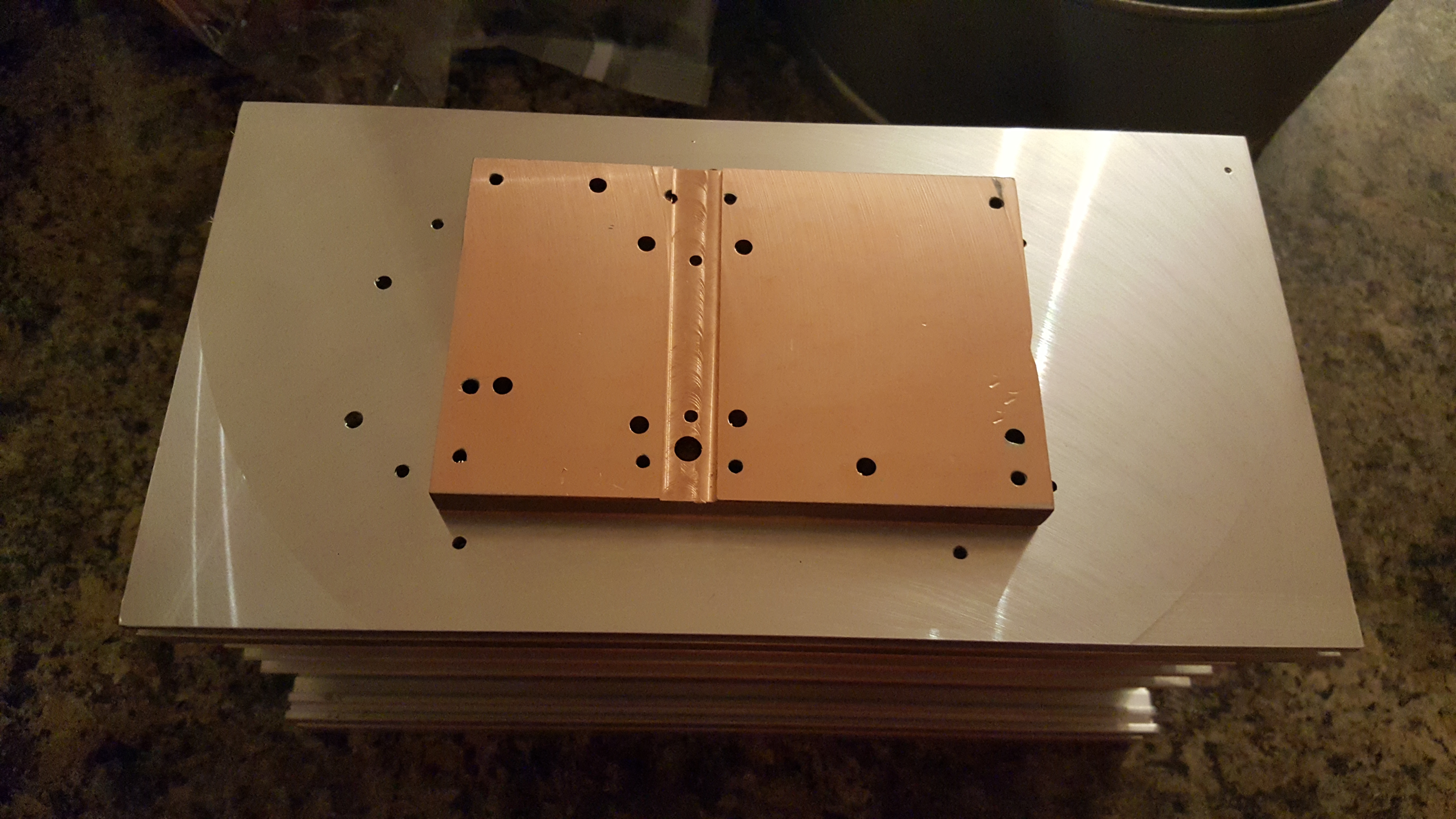
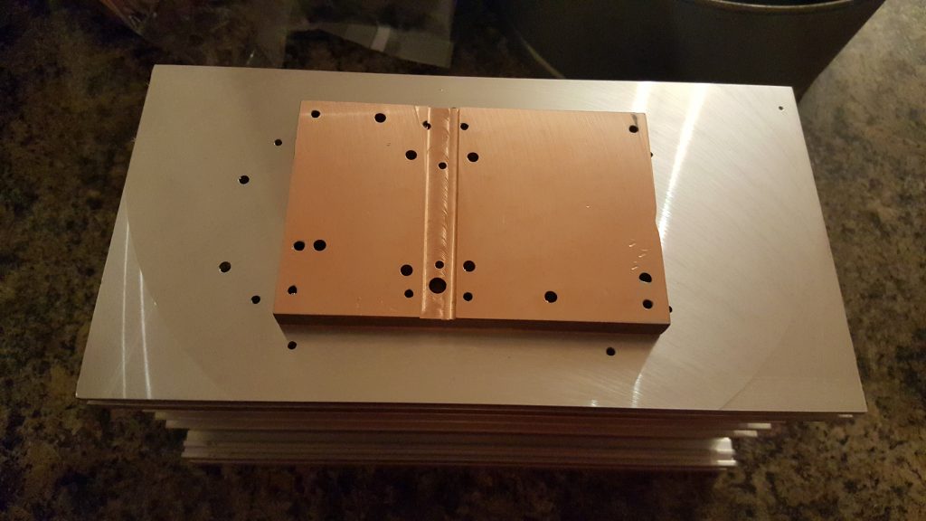
The finished parts. A few machining marks, but the surfaces are perfectly good enough. Some dents on the copper block, but it’s not worth removing all of the material to eliminate these. Using a few drips of water as a substitute for thermal compound, the two mating surfaces stick together very well (with a good vacuum forming). That’s more than good enough for my needs!
Now I just need to wait for the parts to arrive before I can finalise the PCB and transistor mounting! This story continues here: Soldering Expensive Transistors.

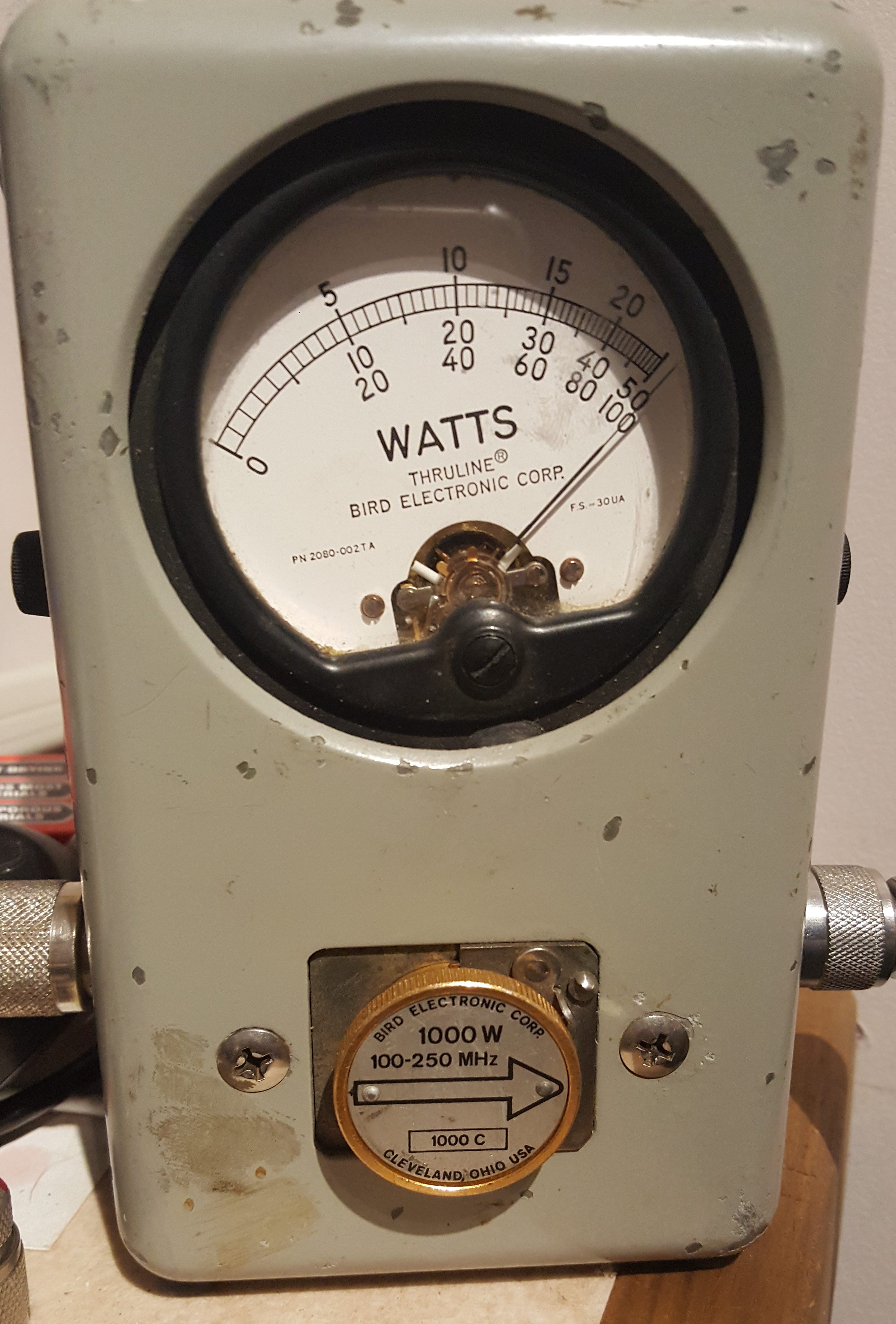 The amplifier was able to maintain in excess of 1000W for over 2 minutes. At this point, the Bird dummy-load started to get a bit warm, so a longer test was abandoned. The amplifier pallet, however, remained cool enough to touch. As the F1JRD original design notes, the 10-Ohm coax balun does become hot (Lionel suggests around 120C at 1kW with no cooling). I, however, used a small fan running slowly to provide a gentle draft which greatly reduced the balun heat.
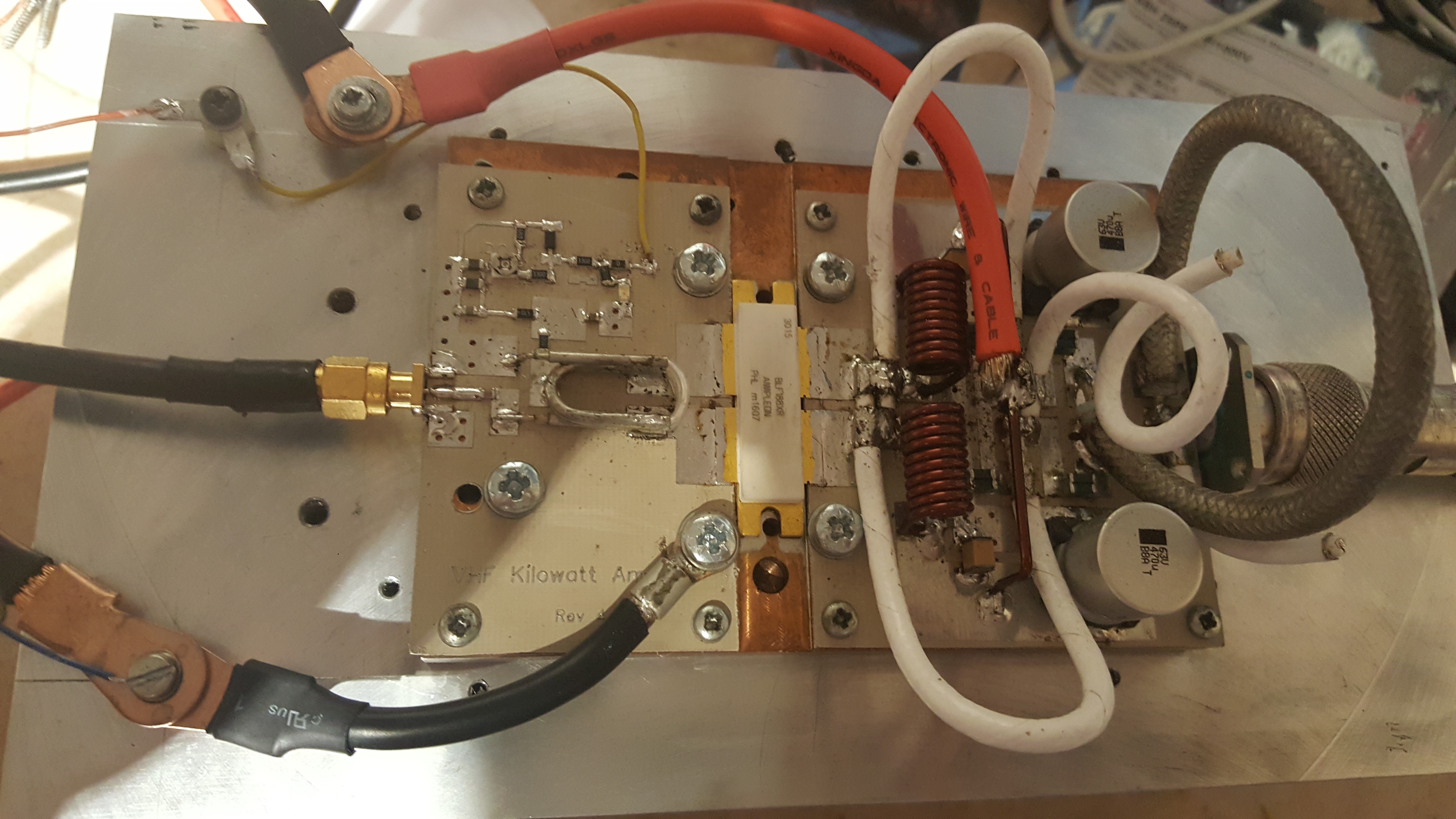 The next step is to add the Dallas-Maxim DS18B20 temperature sensor – the idea is to have the sensor buried into the pallet next to the transistor, to measure the copper heat spreader temperature.