Tag Archives: eme

Some VHF Tinkering

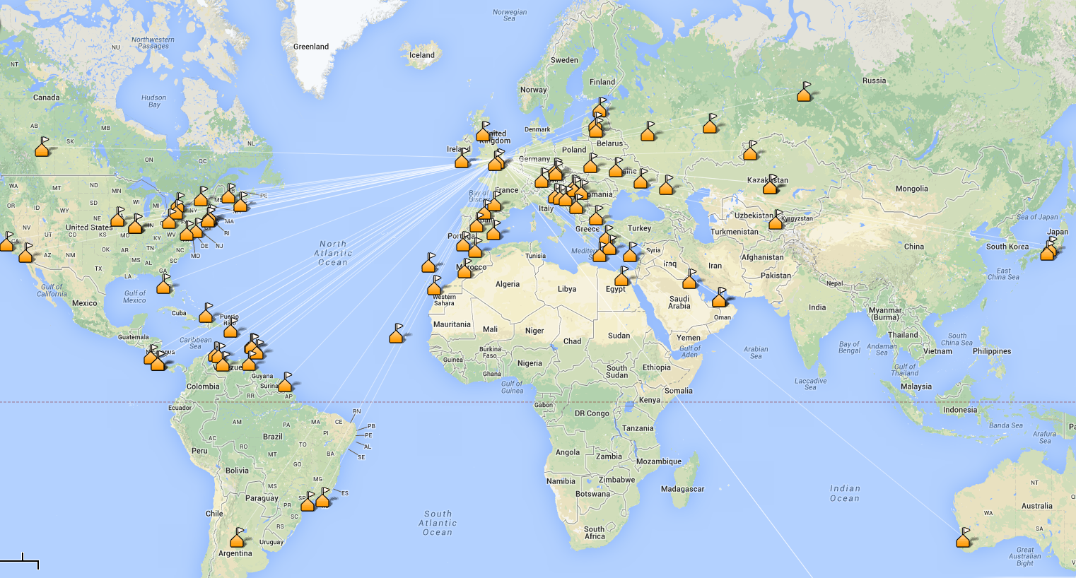
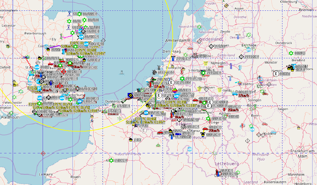
On the way home from work on Friday, my attention was brought to my mobile APRS setup, which was showing received callsigns from Germany, Netherlands, Belgium and France. Once home I decided to connect up my KAM KPC-9612+ TNC to an old Kenwood PMR and see what I heard. The antenna is just a loft-mounted Diamond V-2000, so nothing fancy. About 1 metre of RG58 into the radio. The map is pretty impressive, showing what good conditions were around on VHF at the time. The orange circle shows the ALOHA circle (local reliable APRS network size) – more here – basically the area to which your transmissions would normally be in contention with.


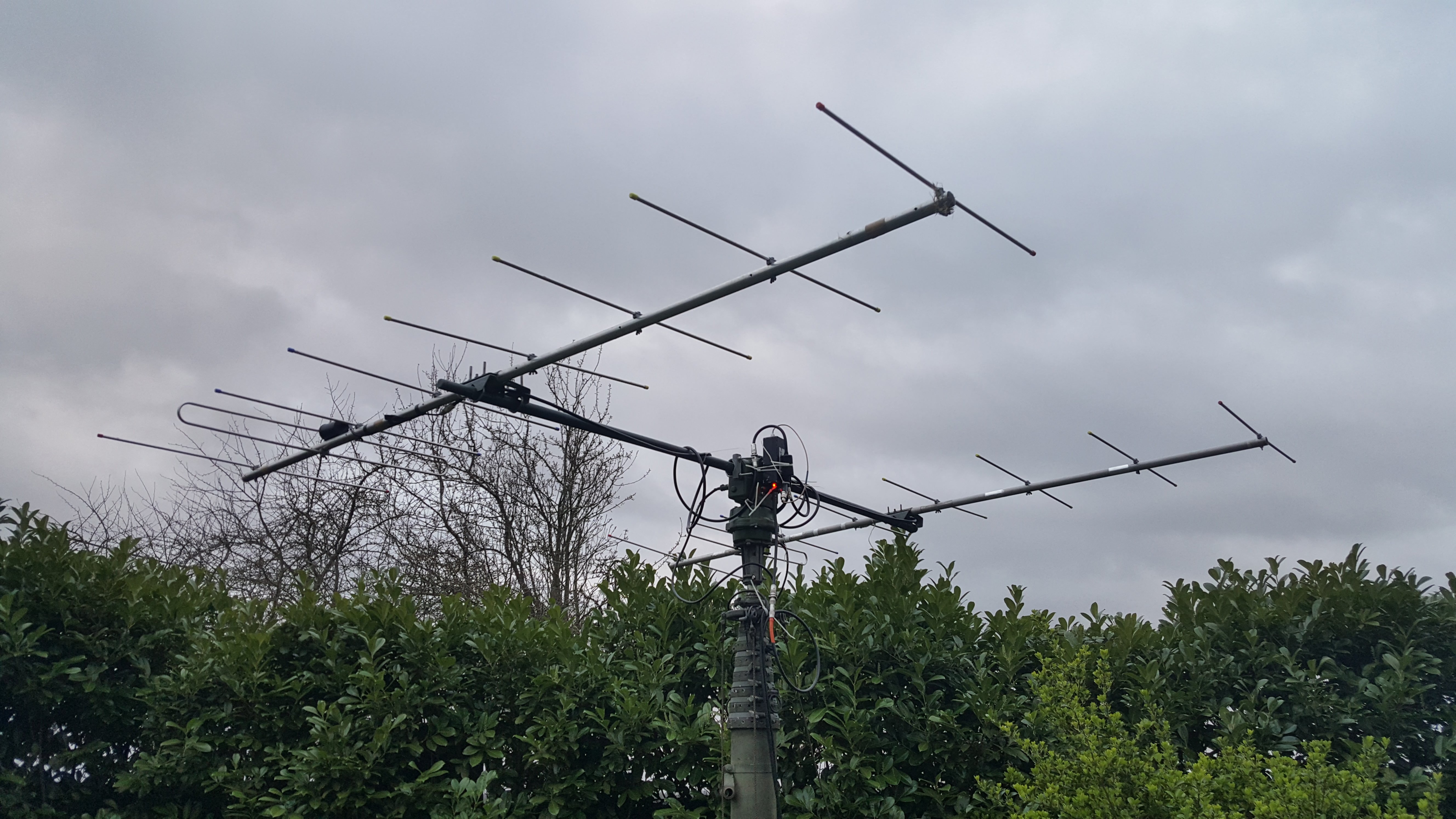
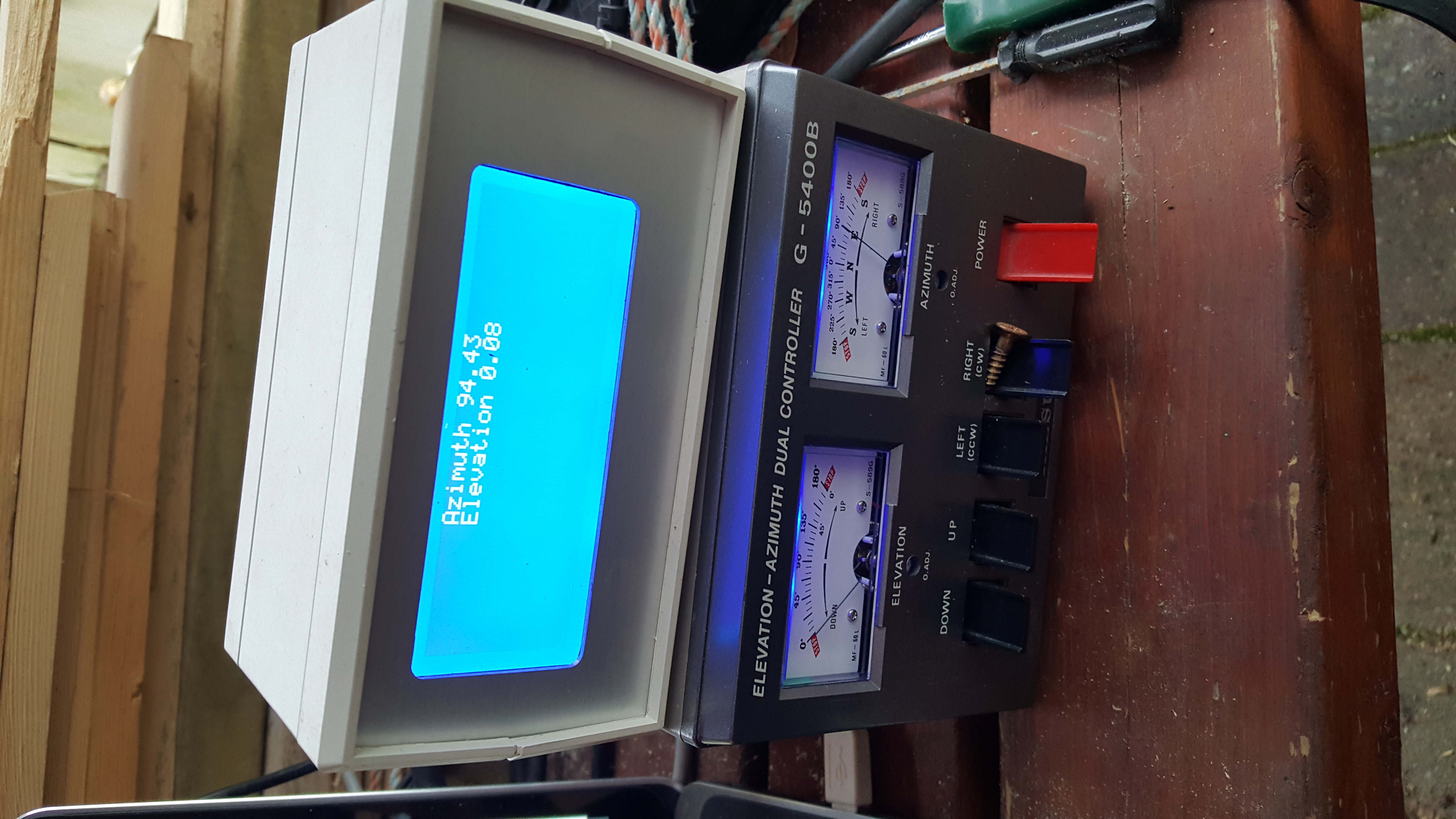
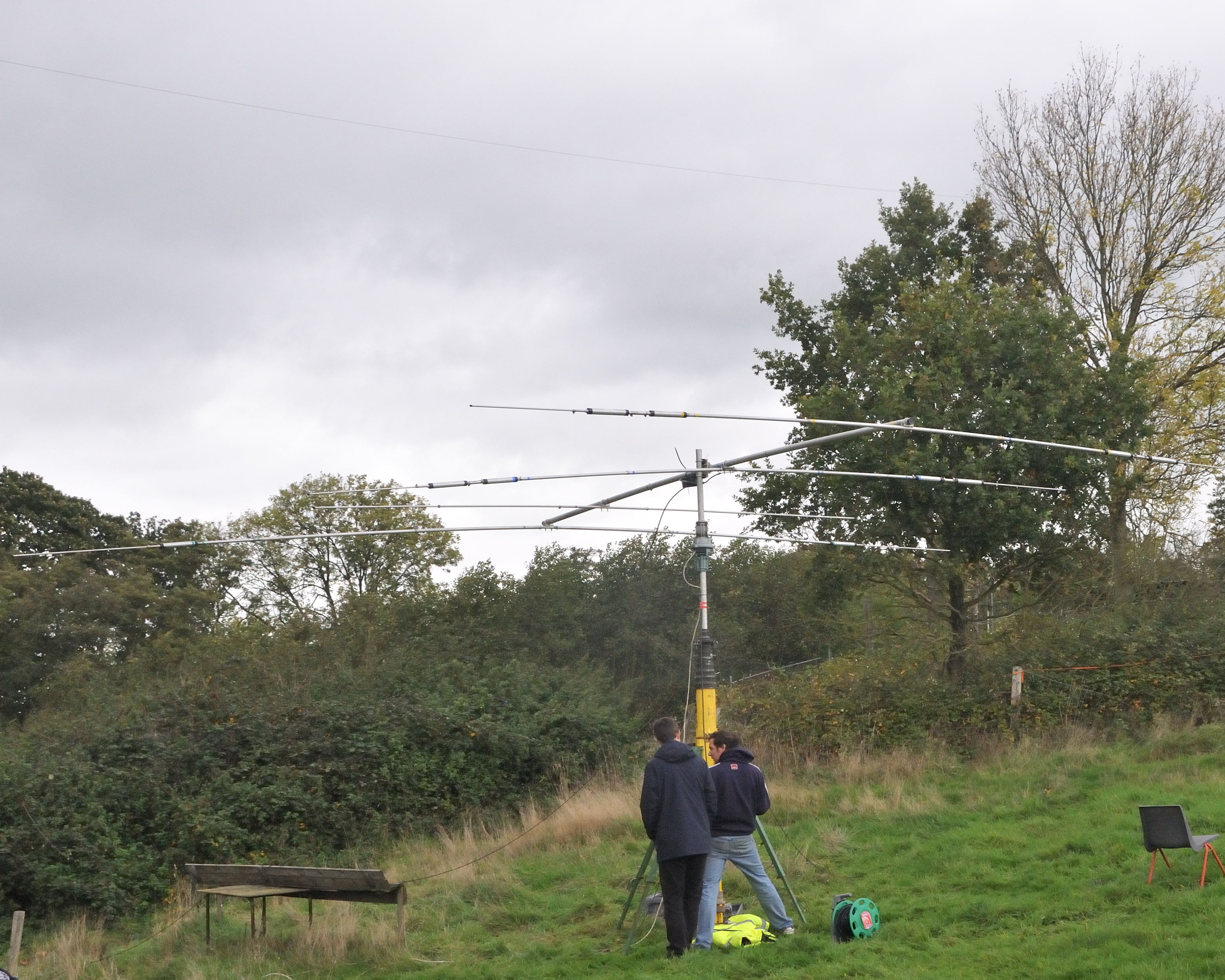
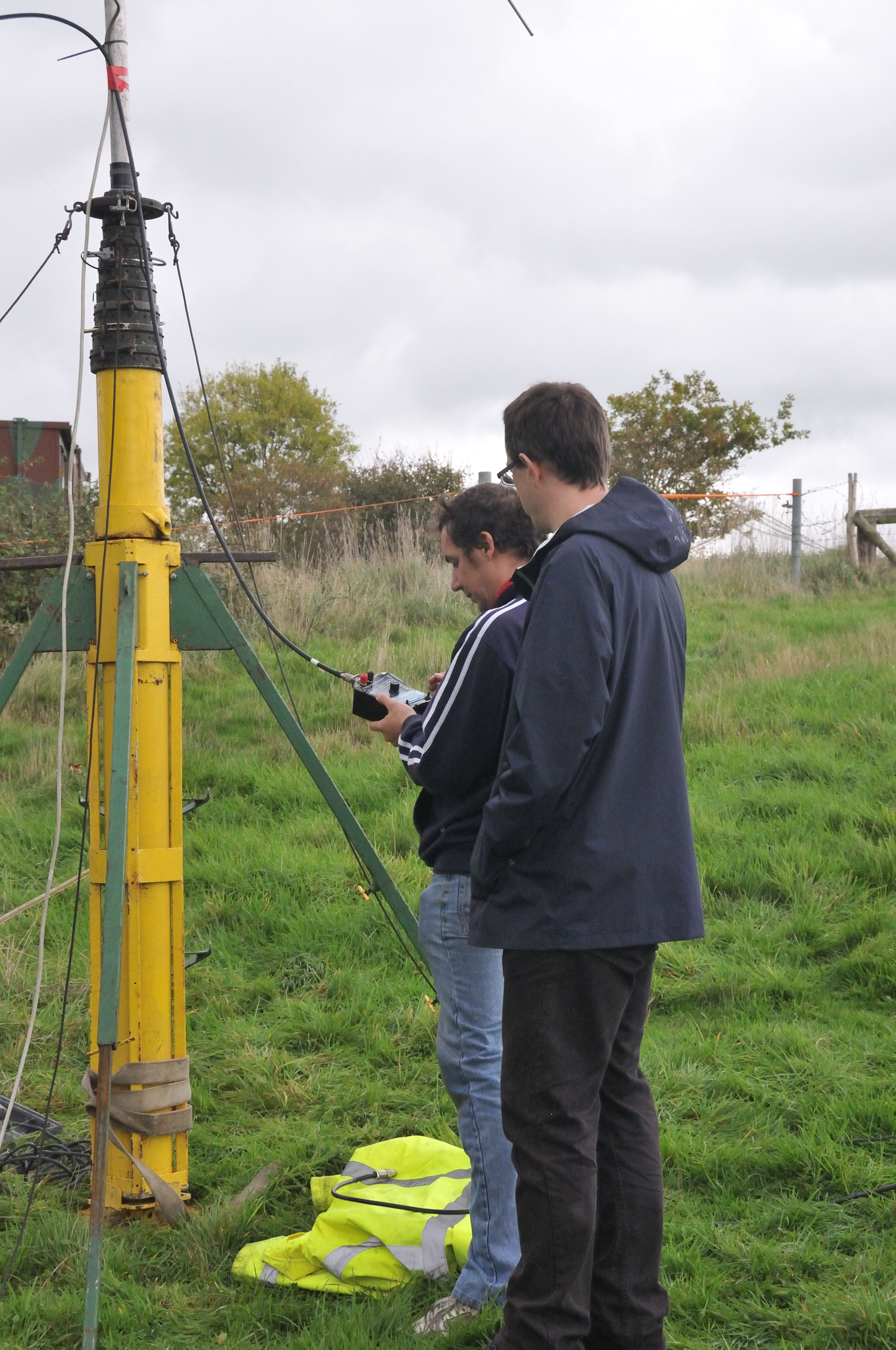
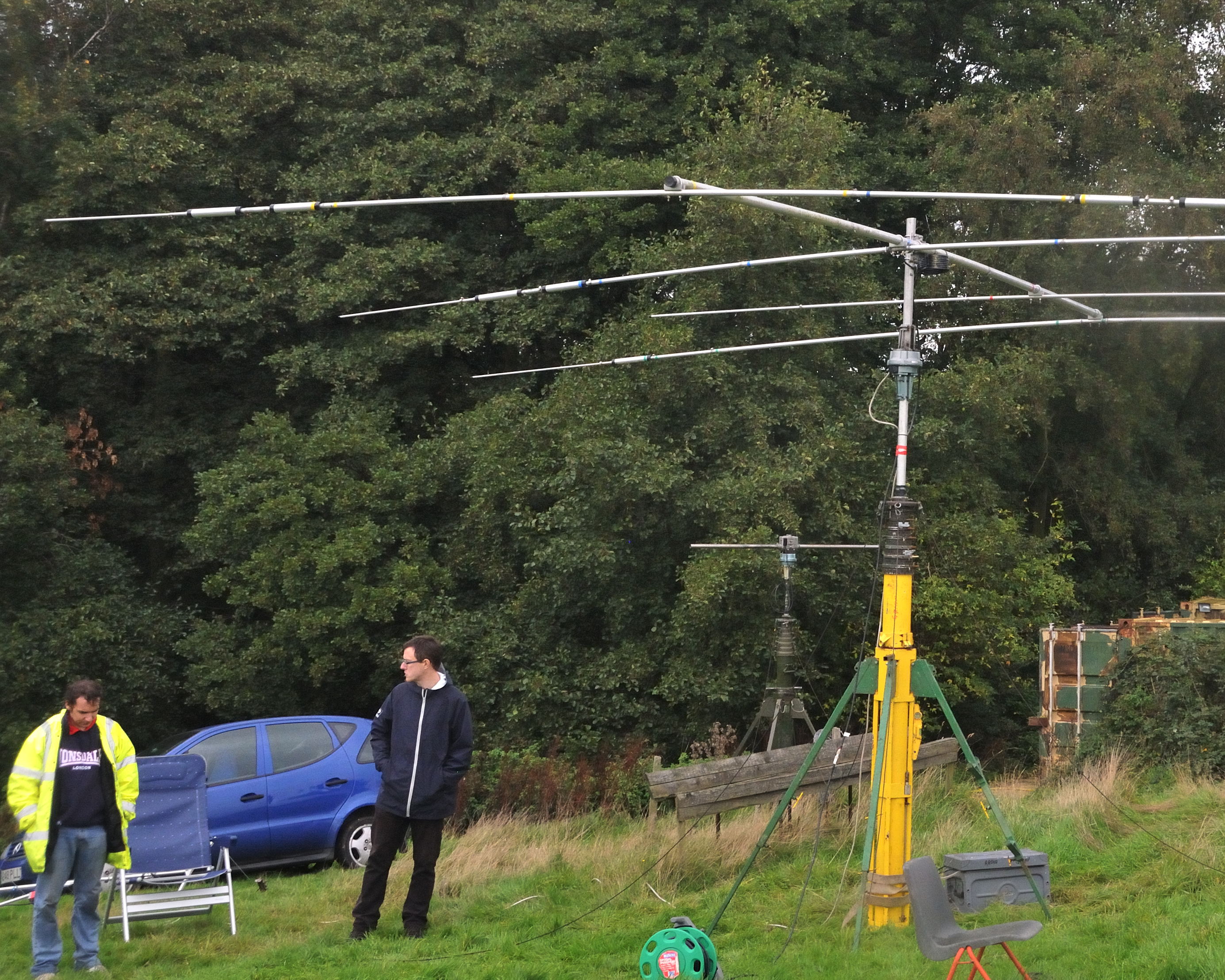
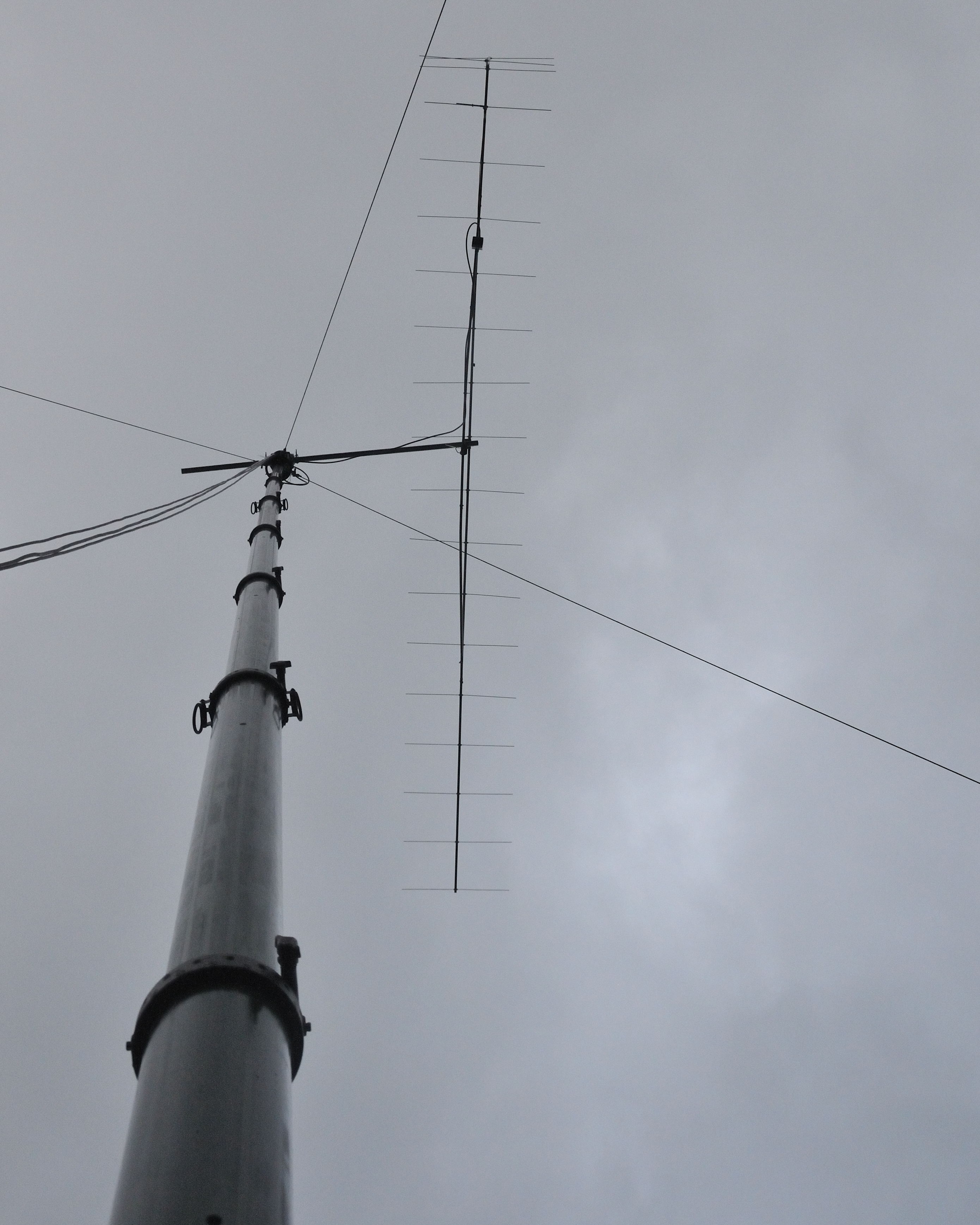
My usual small station EME setup consists of two 9 element DK7ZB Yagi’s bayed at 13 metres. Combined with a Yaseu G5400 Az/El, K3NG’s Arduino rotator interface and YO3SMU’s PstRotator, this is a reasonable attempt at a small station EME setup. Of course you can do it with less, but, it becomes somewhat laborious. With the moon tracking facility of PstRotator, I can set up once, and allow the software to keep the antennas pointing in the correct direction.

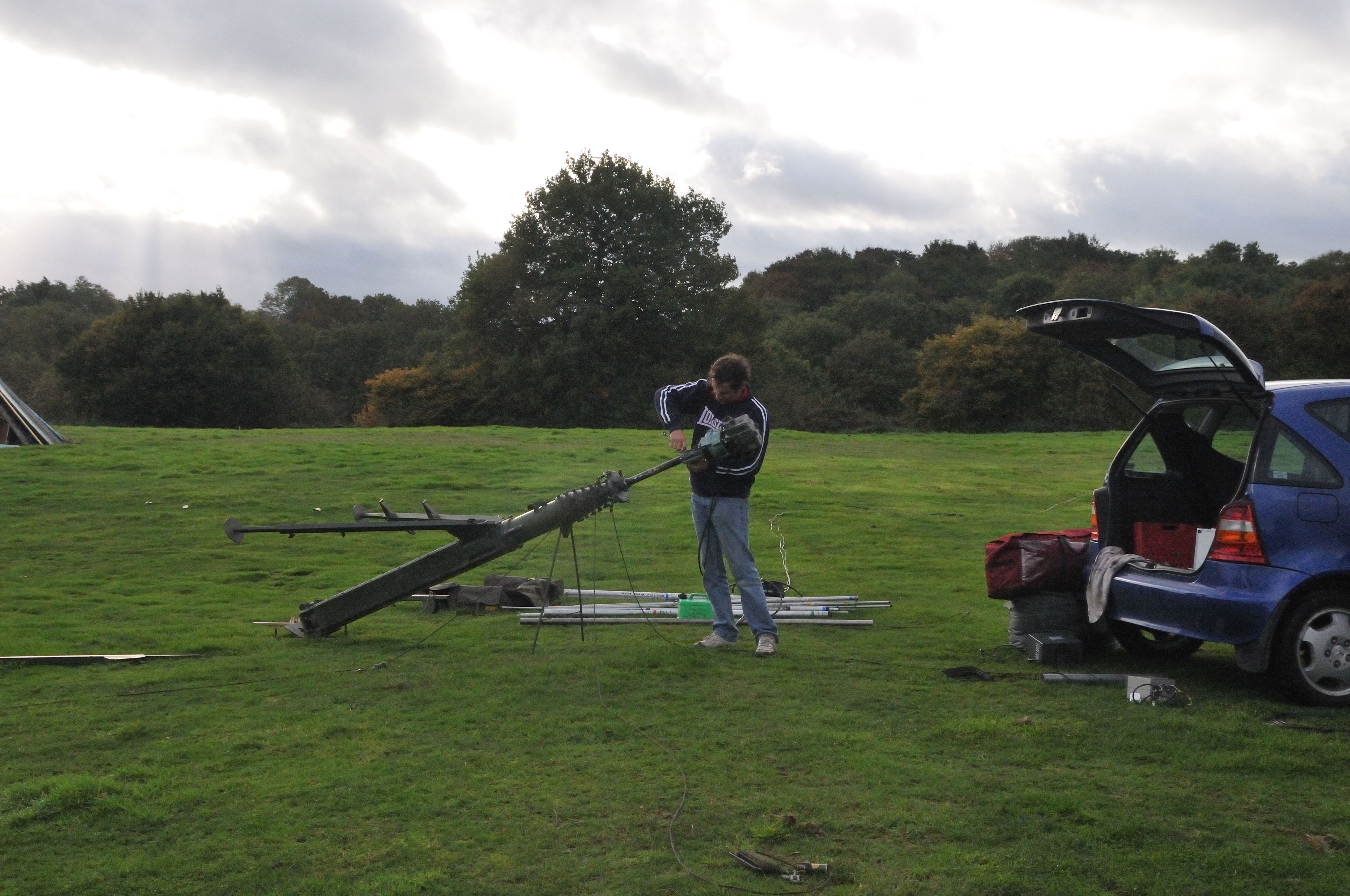
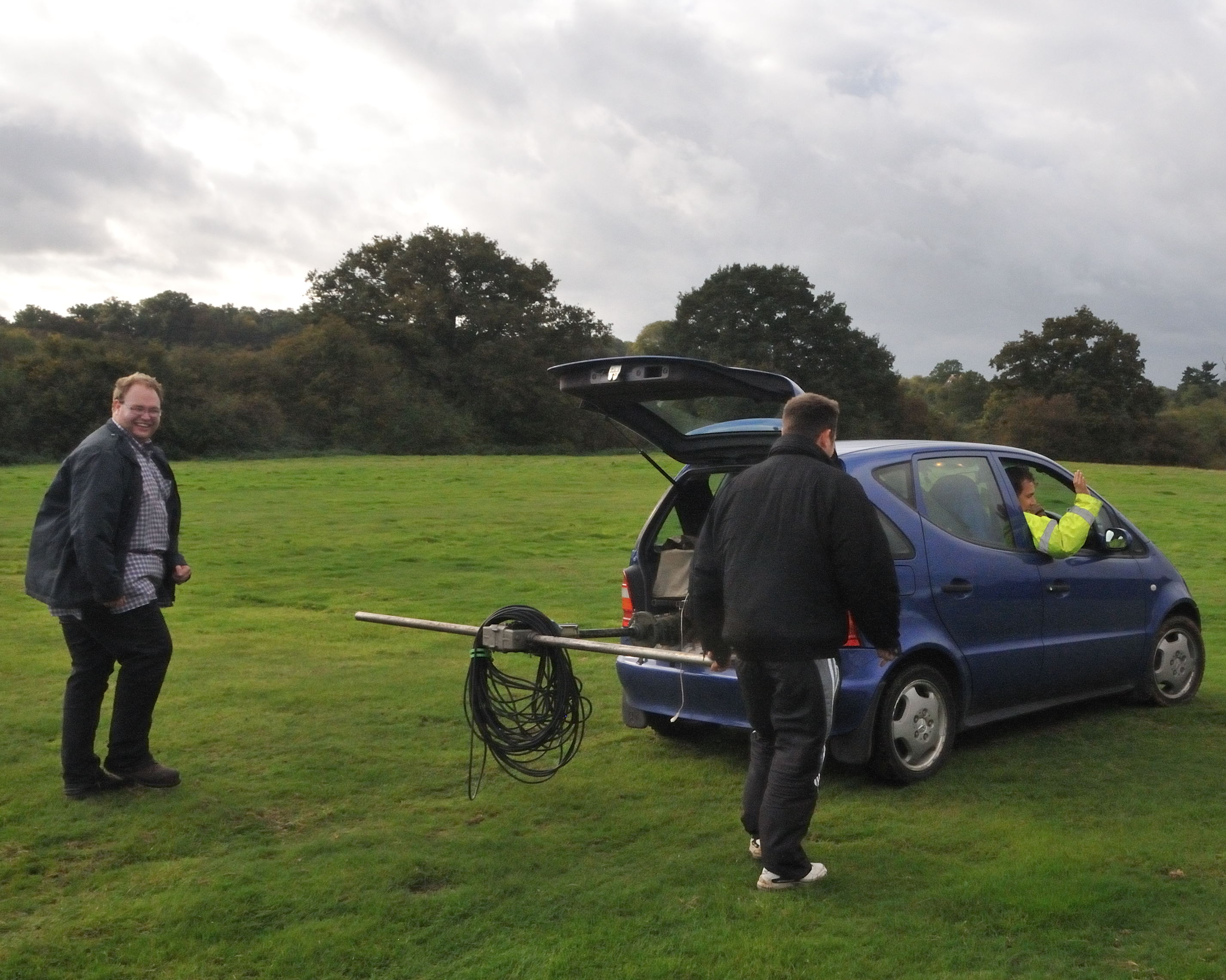
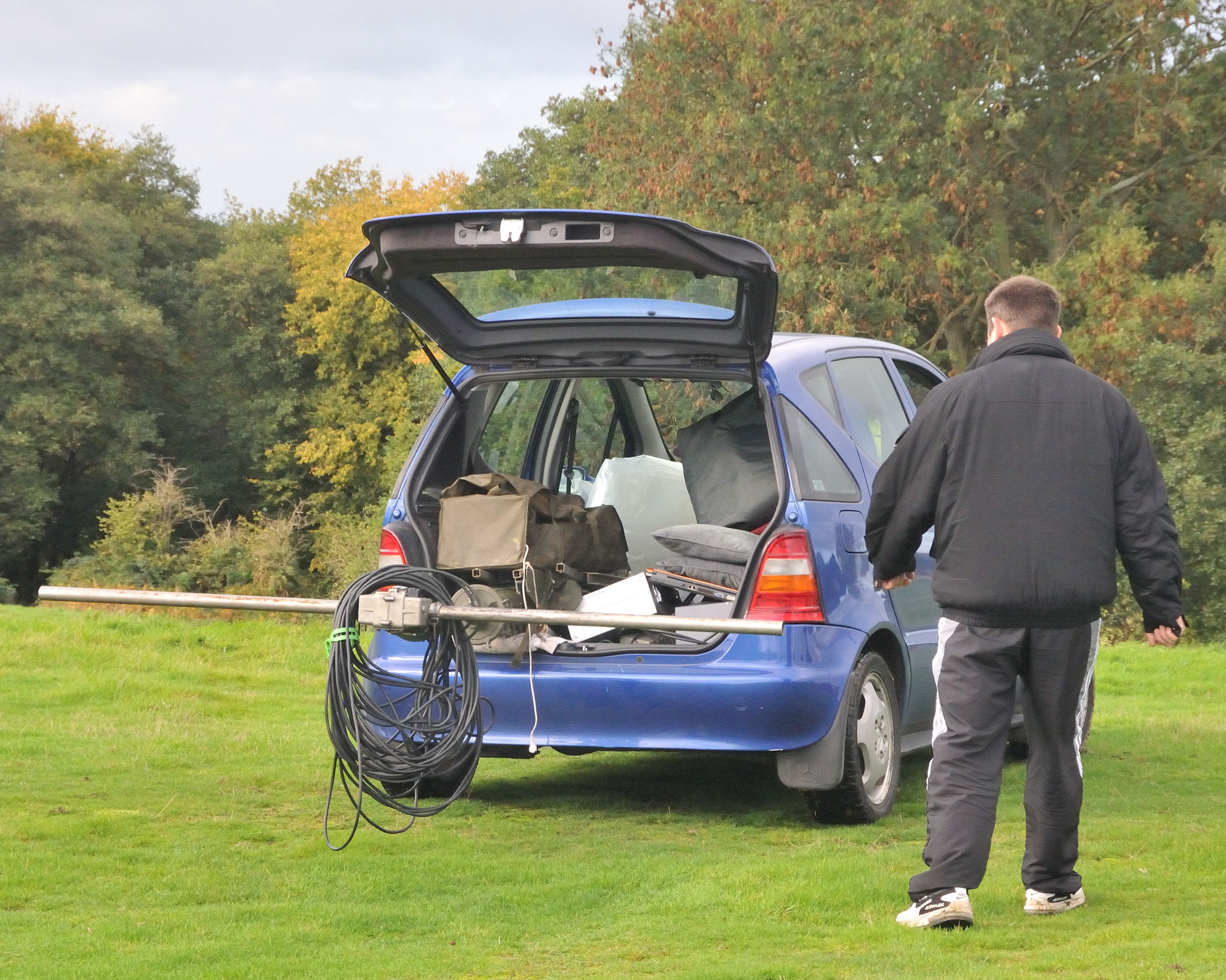
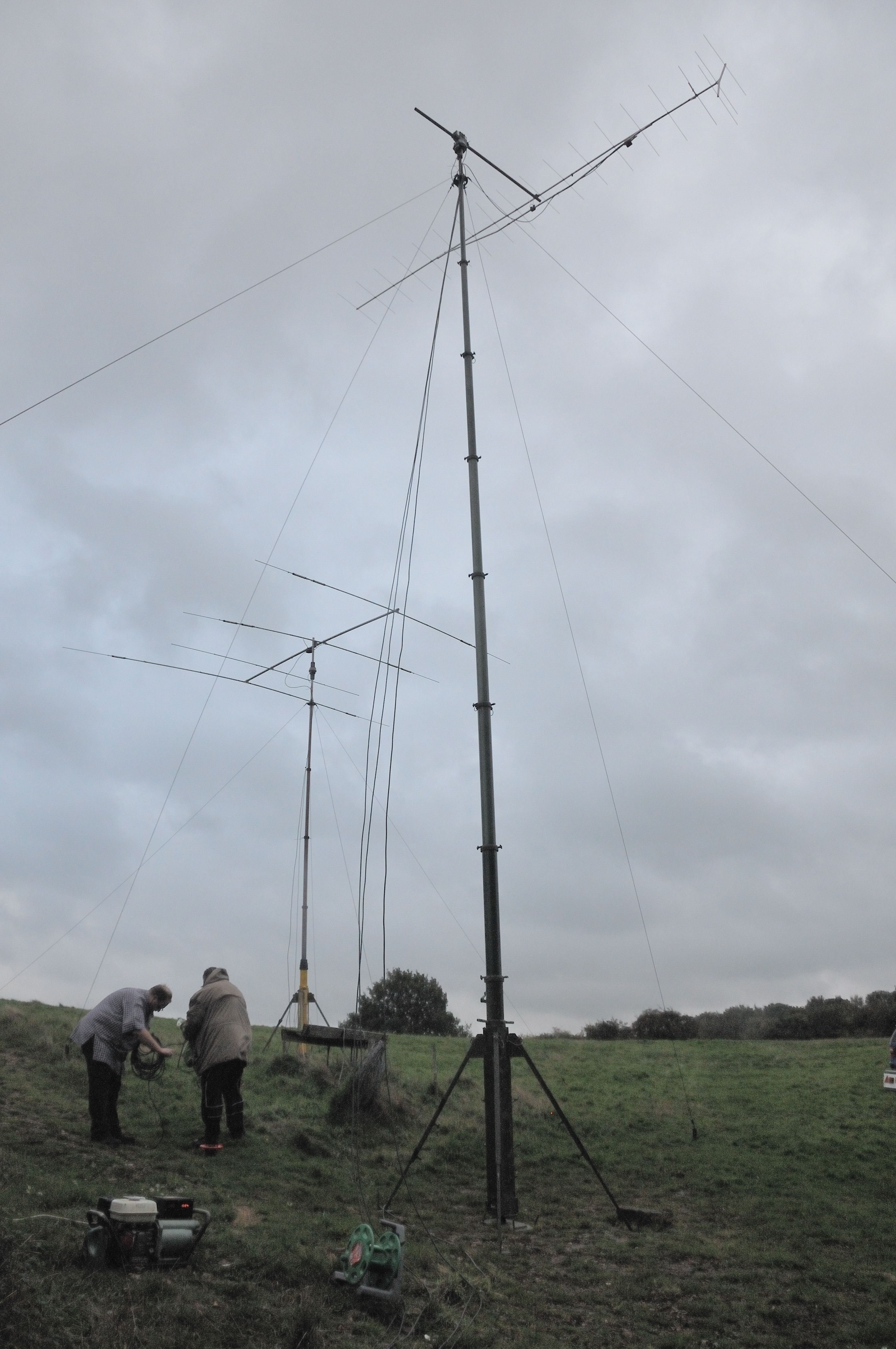
The antennas look like this:

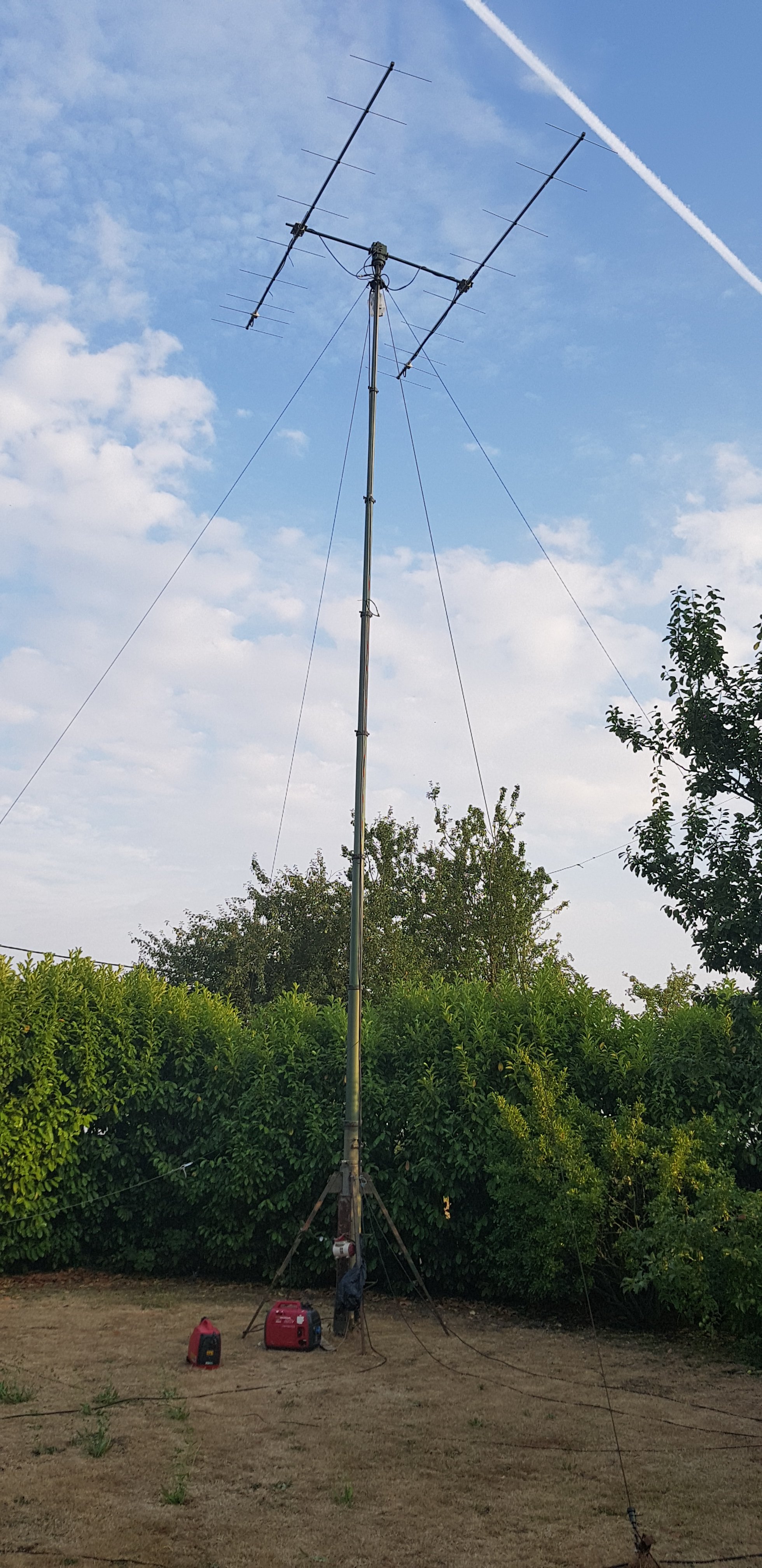
At least we don’t have neighbours!

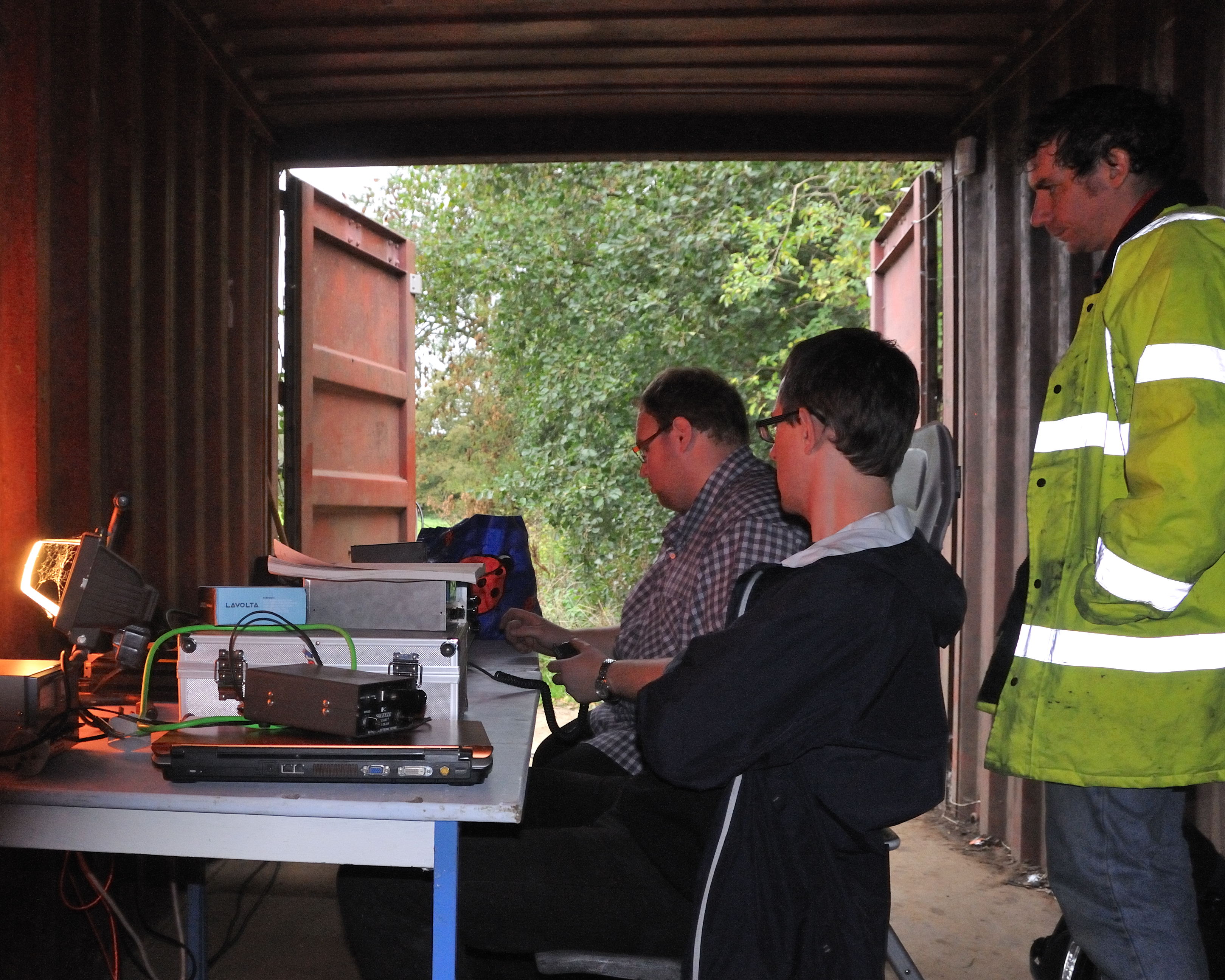
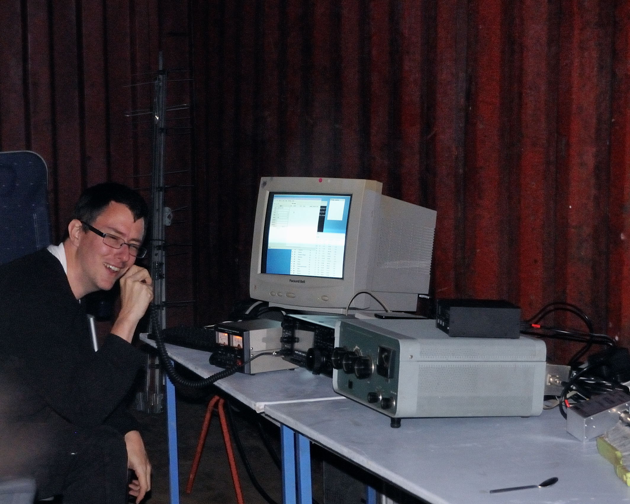
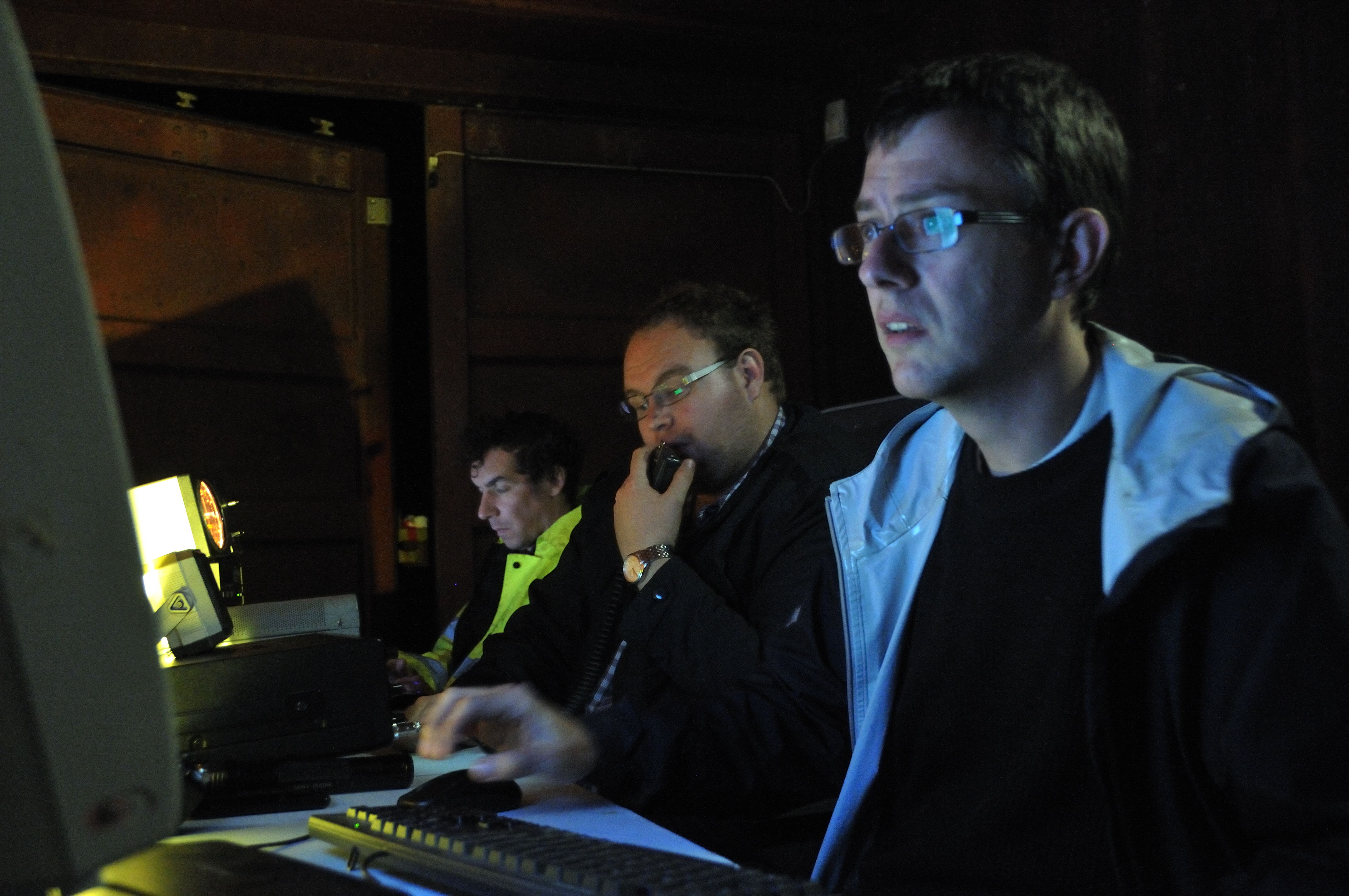
In the shack, I used my Icom IC7100 (since my Anglian transverter was having issues), a homebrew 1kW solid state amplifier, and PGA144 preamp based on the PGA-103+.

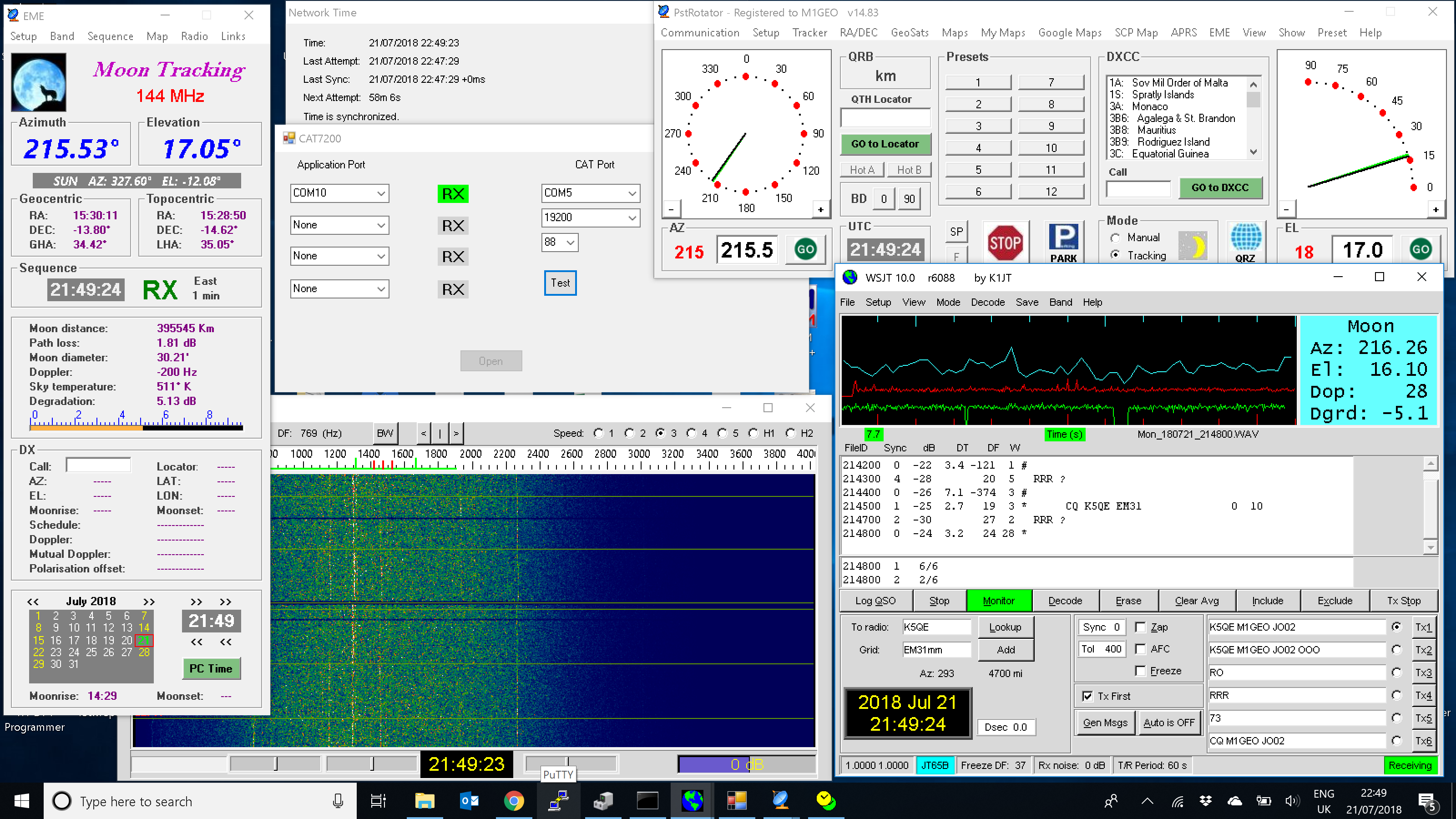
Most of the spare time during the weekend was taken up by relearning everything I had forgotten since I last tried EME and VHF data modes. I was able to confirm the setup was working correctly using GB3NGI beacon as well as some others on the make-more-miles on VHF site. Within around an hour I was successfully receiving SP4KM, ZS4TX and K5QE via the moon on 144 MHz.

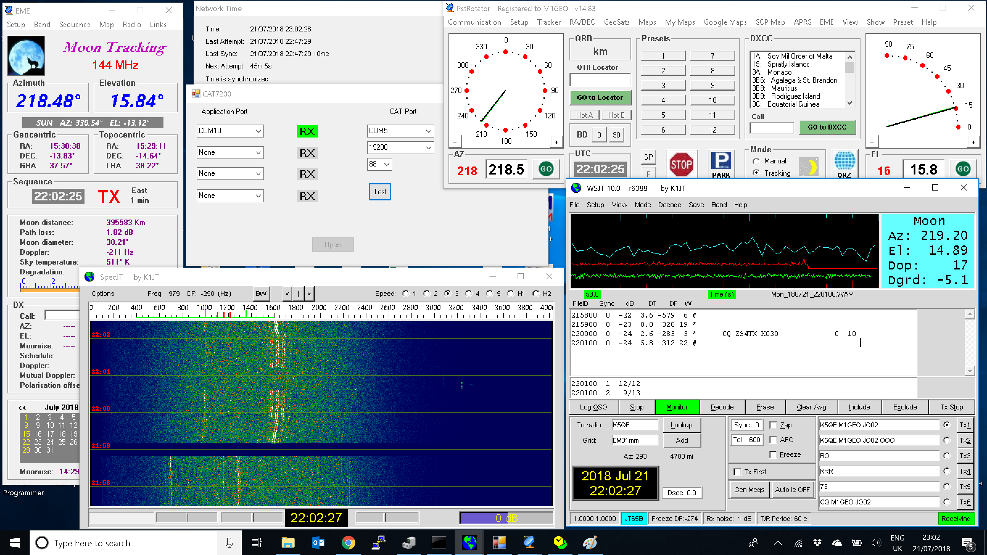
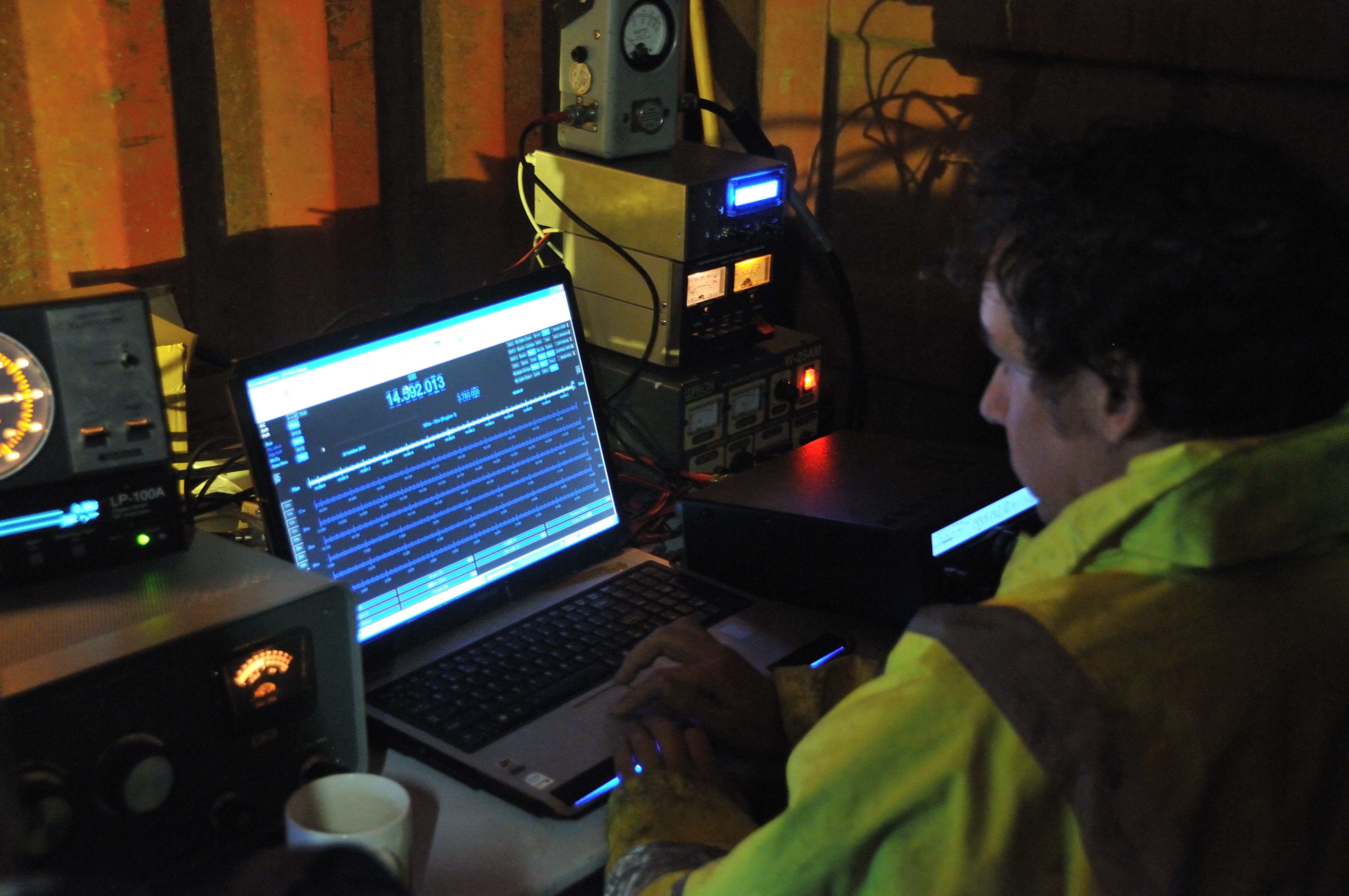
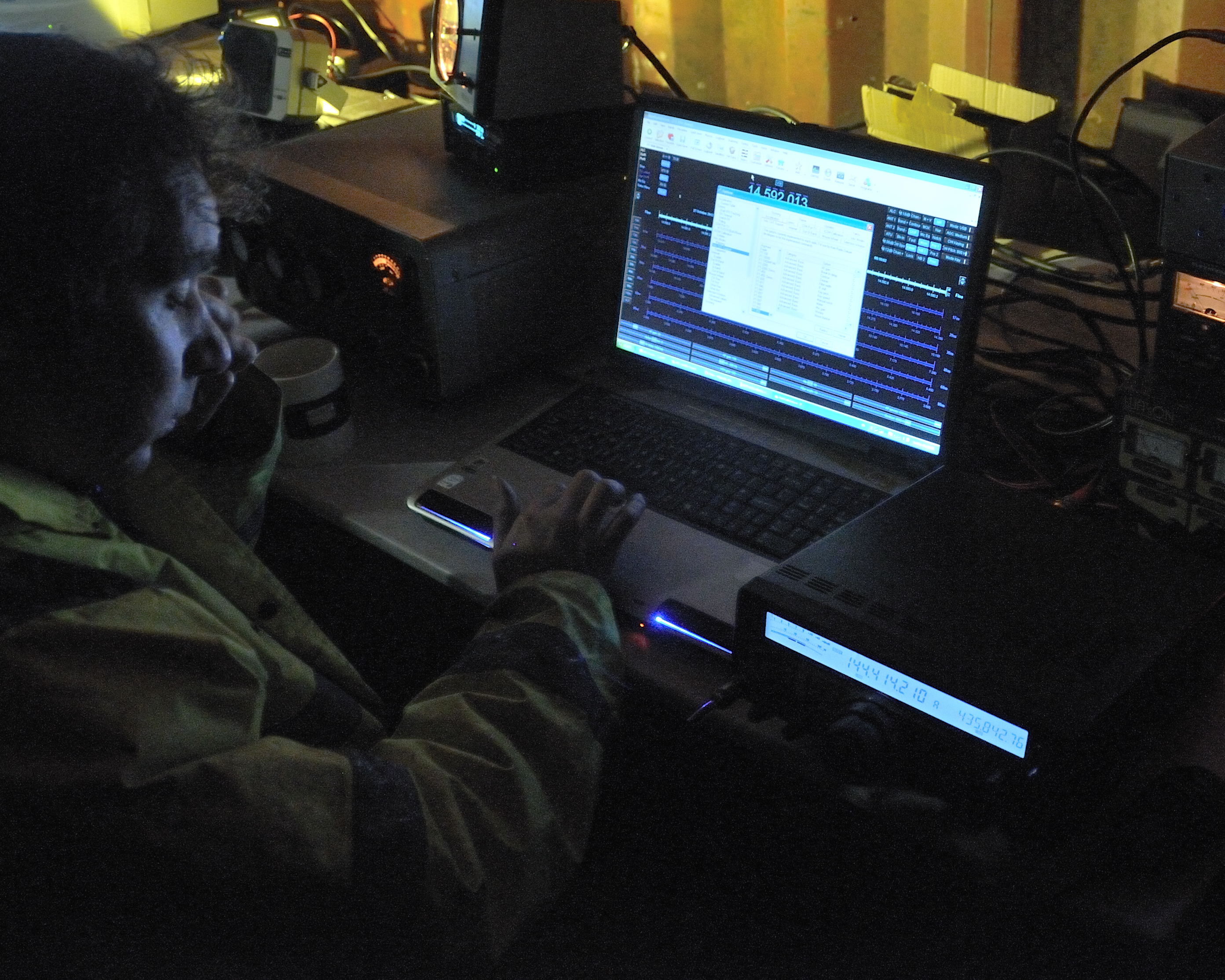
The screens above are rather busy with the rotator controller, NetworkTime program for keeping the PC clock synchronised via NTP, and CAT7200 which usefully translates the DTS/RTS line style PTT interface to a newer CAT/CI-V instruction.

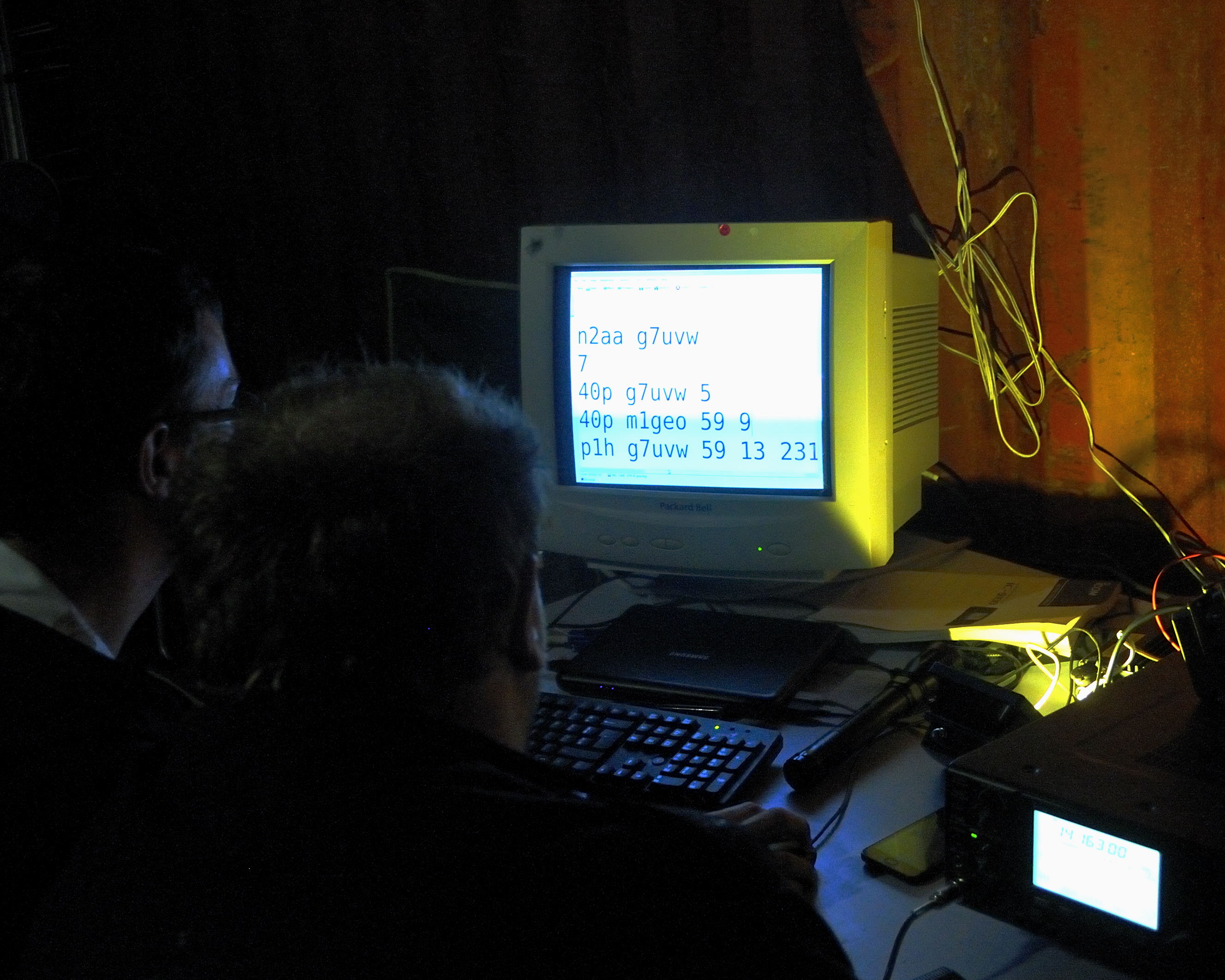
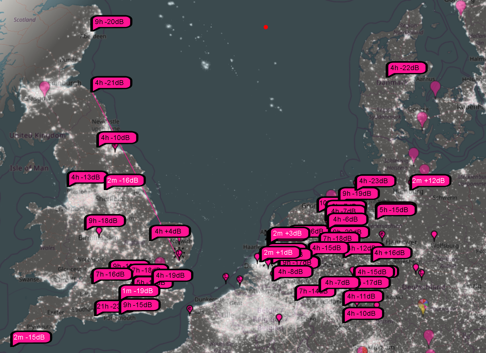
As mentioned, when the moon was below the horizon, I also played around with other modes. SSB resulted in few contacts, but more than the ‘none’ I managed on CW. I quickly found my feet again on FT8, working into Germany, Denmark and the Netherlands. At the end of the weekend, PskReporter was showing the below map for M1GEO on VHF:

I have promised myself two things:

  1. To get on VHF more often. Well, do do more radio, basically!
  2. To finish the 144 MHz amplifier off. I have the basic functionality, but it’s lacking a user interface and other nice features. The hardware is there, but there’s no translation onto the nice graphics LCD.

Earth Fault on Yaesu G-5400B

I brought a Yaesu G-5400B azimuth and elevation rotator & controller system from a friend at a local radio club about 6 months ago. I brought the rotator as faulty. When I powered the rotator up on the bench, I couldn’t find any fault. I built a PC-Rotator controller interface similar to the Yaesu GS-232 interface to accompany the G-5400B controller, and while doing extensive testing, no fault with the rotator became apparent.

This weekend, following the acquisition of some fibreglass poles at the Rosmalen hamfest, I decided to set up my bayed 144 MHz beams with the azimuth/elevation rotator. After mounting the antennas on the beam, fixing the phasing harness and the mast-head preamp and connecting the cabling, I noticed that the rotator was no-longer working correctly. Although both of the rotators would turn, the azimuth display on the control box failed as soon as the coax was connected to the radio (or more specifically, the coax screen connected to anything in the shack that was earthed).

Using a multimeter to inspect what was going on, it was clear that the coax ground was sinking current sent to the potentiometer inside the azimuth rotator. Looking at the schematic, the cause would appear to be that the +6V side of the feedback potentiometer was somehow becoming shorted by the connection of the coax screen.

I decided to pop the cover and see what was going on

From inspection, you can see that the original hypothesis was correct and that one side of the potentiometer was shorting to the casting – the brown wire had been caught between the plate visible and mounting point. Since the antenna metal is grounded via the coax, this effectively shorted out via the broken insulation on the brown wire.

The repair was the simple process of snipping the broken wire, and soldering a new one in. I also used two tiny cable ties to bundle the wires to the potentiometer and to ensure they were kept away from the mounting hole, too.

The rotator goes back together easily assuming you have followed the usual advice when dismantling these rotators; marking the case and internal gear such that it can be reassembled with the same aligning.

After finishing the reassembly of the the G-5400 rotator, being sure to grease the bearings, I was ready to mount the antennas and try again.

This time around, the rotator functioned perfectly. The total repair took around an hour. Now I need to finish the PC interface to make use of the fancy graphics LCD!

CQWW SSB 2013

This map shows some of the stations worked during CQWW SSB Contest, 26-27 October 2013. Operations using M0STO’s tri-band 4-ele Yagi and 300W from the Kelvedon Hatch Secret Nuclear Bunker (GB0SNB) operating as G3XBF.

We set out with the aim to work as many DXCC entries as we could within the 24 hours we were able to operate. Operations started at 16:40 UTC on the Saturday an finished at 15:10 UTC on the Sunday; operating most of the night. 54 DXCC entries worked.

The location details are from QRZ.com, where possible.

Map

Click the map once for image details, and again for high resolution image.

Photos

Here are a few pictures from the 2013 CQWW contest, taken by Peter Allen, G0IAP.

Pictures from CQWW 2013

M0STO setting up the EME SCAM 12 on the top field
Pictures from CQWW 2013

Moving the SCAM 12 to a lower field because of high winds
Pictures from CQWW 2013

M0YOL guiding M0STO in moving the beam in his car
Pictures from CQWW 2013

Erecting the HF beam on another SCAM 12
Pictures from CQWW 2013

G7UVW and M0STO tuning the beam & checking the SWR
Pictures from CQWW 2013

G7UVW and M0STO reflecting on the erection of HF beam and VHF EME beams (background)
Pictures from CQWW 2013

Inside the lockup at GB0SNB
Pictures from CQWW 2013

Tuning the linear up
Pictures from CQWW 2013

2m Yagi looking a bit bent, on the Az/Ele rotator for EME
Pictures from CQWW 2013

Both beams as coax is run into lockup
Pictures from CQWW 2013

G7UVW operating and logging
Pictures from CQWW 2013

M1GEO swinging the beam as G7UVW is operating
Pictures from CQWW 2013

G7UVW logging as M1GEO operates
Pictures from CQWW 2013

G7UVW drinking tea as M1GEO operates
Pictures from CQWW 2013

M0STO setting up EME equipment
Pictures from CQWW 2013

M0STO configuring HRD to track the moon
Pictures from CQWW 2013

M0STO deep in the settings!
Pictures from CQWW 2013

G7UVW and M1GEO tidying their “private” log, collecting their own DXCCs!