
Introduction
When experimenting with the WellGood Loop antenna, I came across the PA0RDT MiniWhip design referenced in several places. I traced the original articles as best as I could to pa0rdt design notes and pa0rdt English design notes.
Since several other amateurs were following my progress and interested in my experiments, G8OCV and I decided to design a simple PCB based on the PA0RDT design. If anyone else is interested in spare PCBs, please contact me.
The construction of the PA0RDT MiniWhip is simpler than the WellGood Loop since there are no inductors to wind, but during my testing, I have found the loop to have slightly better performance.
The rest of this page is dedicated to the construction of the PA0RDT MiniWhip V2 PCB.
Schematic & Bill of Materials
Amplifier
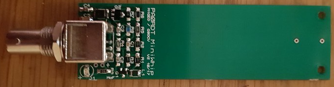
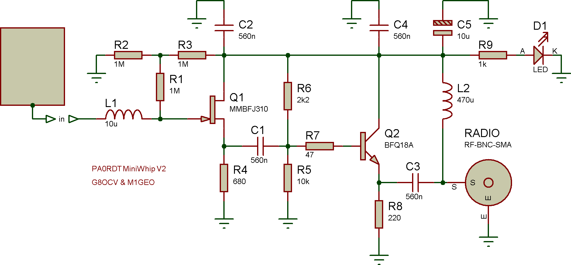
The below schematic is closely based on the original PA0RDT design. The PCB is made using 1206 surface mount parts (large enough for anyone to solder!) and SMT transistors. The PCB will take a BNC or board edge SMA. The output stage of the original design uses a 2N5109 power RF VHF transistor, but these parts are becoming increasingly difficult (expensive) to obtain and aren’t surface-mount, so I have replaced this part with a BFQ18A SMT part. The input stage is an MMBFJ310 (SMT J310). The antenna patch region measures 30x75mm. It can be expanded by using the pads. Power is supplied via coax as per the original design.
 With the order codes specified, I have gone for the cheapest way to acquire the required number of components at the time of assembling this list. Often this means purchasing 100 components when only 1 is required. However this represents the most cost effective solution and the spare SMT parts made excellent shack carpet-glitter!
| Component | Value | Count | Supplier & Notes |
| PCB | PA0RDT MiniWhip PCB | 1 | I have spare boards, Contact Me. |
| C1, C2, C3, C4 | 560nF (680nF for cheapness!) | 4 | RS 652-4041 |
| C5 | 10uF | 1 | RS 698-3724 |
| R1, R2, R3 | 1MΩ | 3 | RS 722-0065 |
| R4 | 680Ω | 1 | RS 669-6540 |
| R5 | 10kΩ | 1 | RS 721-9908 |
| R6 | 2.2kΩ | 1 | RS 842-9184 |
| R7 | 47Ω | 1 | RS 721-9715 |
| R8 | 220Ω | 1 | RS 721-9769 |
| R9 | 1kΩ | 1 | RS 788-3984 |
| Q1 | MMBFJ310 | 1 | RS 625-5745 |
| Q2 | BFQ18A | 1 | RS 626-2715 |
| D1 | LED | 1 | RS 228-5562 |
| L1 | 10uH | 1 | RS 124-1871 |
| L2 | 470uH | 1 | RS 725-5197 |
| CON1 | BNC or SMA | 1 | RS 512-1225 (BNC) or RS 125-8191 (SMA) |
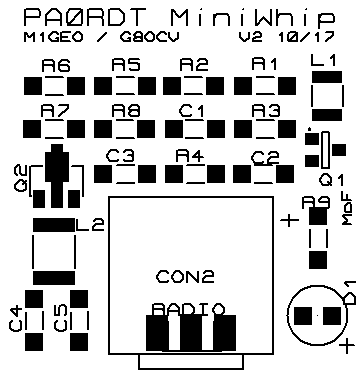
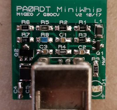
The PCB
The version 1 PCB served as a proof of concept design, which resulted in some slight tweaks before V2 was ready.
Version 2.0
 |
 |