
See APRS for more general APRS stuff. You can order PCBs for this project here, or you can contact me. Firmware is here.
All files are here, but no explanatory text. There’s enough information to make the boards up, parts and placement, and links here to source code, but there’s no “guide” as such for this project, just the silk screen and schematic.
The aprstracker firmware version 0.12 (supporting 9600 baud GPS) by PE1ICQ and PE1RXQ can be downloaded here: aprstracker-0.12.tar.gz. It is not on the author’s site, since there are bugs with the altitude code. However, the code is still useful for 9600 baud GPS. Use version 0.11 if you want altitude.
![]()
![]()
![]()
![]()
![]()
![]()
![]()
![]()
![]()
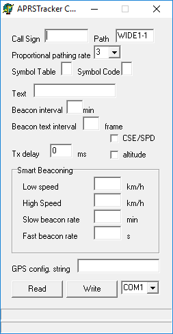
Programming your callsign
After you have programmed the PIC with the firmware above, you will then need to enter your user data, such as callsign, and other parameters. Information on how to do this using a Linux Live CD is provided by PE1ICQ and PE1RXQ. However, recently, Nigel G4ZAL brought to my attention some software by Jedrzej SQ2DK, which can be downloaded from here (or here), and allows for much easier programming via Windows.
Using TTL GPSes
As GPS receivers are moving on to USB and Bluetooth, they become increasingly more expensive. The tracker, as with pretty much all trackers, uses RS232 input. Many of the cheap GPS receivers on eBay such as the VK16HX/VK16U6 receivers have TTL output for direct connection into Arduinos and other hobbiest projects. To make these compatible with the tracker, one needs to invert the TTL data (i.e., 1 becomes 0, and 0 becomes 1). This is because traditionally a MAX232 would be used.
Although a MAX232 is the right part to use, a simple transistor inverter will suffice, and I have used one on several occasions. The very poor hand drawn sketch was put up in a rush to aid with the explanation:
![]()
![]()