V-Band () and Vail () – online ham-band platforms where you can practice CW with others
Morse Code Battleships (N4BKY & N4FFF) – an interactive battleships game with CW interface
I really also like MorseWalker (W6NCY), a joke on the contest practice software MorseRunner (VE3NEA). I really enjoy using MorseWalker – but it’s receive practice only.
For those that need CW paddle input, you really want to be using an interface – that way, you can connect your favourite key (or, failing that, the key that you’ll be using) to your computer and practice sending with that key…
Interfacing Options
There are a couple of existing interfaces:
The Vail Adapter is a full project with custom PCBs, etc., and works well.
Because I am impatient and had the parts, I decided to build my own.
The Build
I took inspiration from the OZ1JHM’s hamradio-solutions-vband-interface code. I am mainly interested in the paddle operation, but, you could modify this code easily to just send a single keyboard-button press for the straight key.
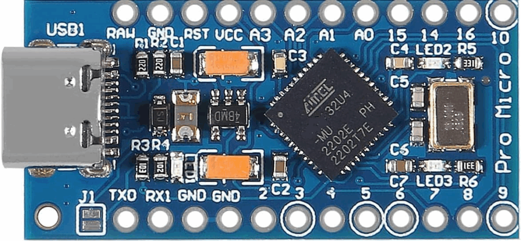
It’s important to note that you’ll need an Arduino where USB is directly connected to the Arduino chip and not via an UART IC since these only support UART ports and can’t emulate a keyboard. This means that you cannot use devices based around the Atmega328P.
The code below is for an Arduino Pro Micro (I used a USB C version) which is based on the Atmega32U4:
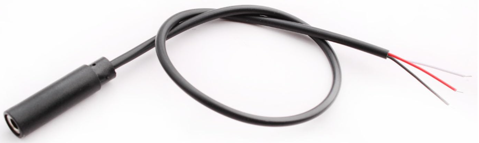
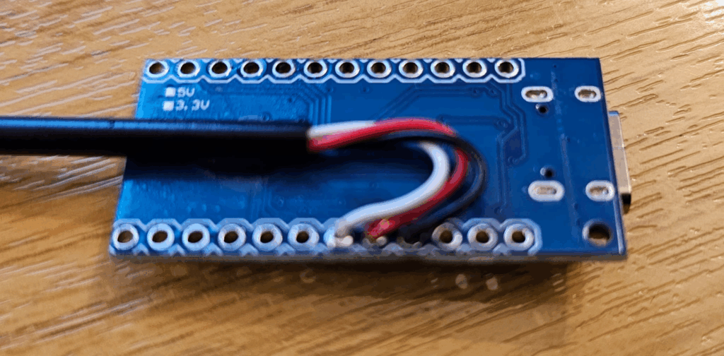
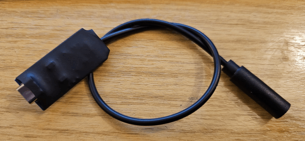
You’ll also need a way to connect your key easily. I used a moulded 3.5mm (1/8in) stereo socket on a short cable (available online cheaply) to create a nice connection, that would allow me to easily plug & unplug my key.
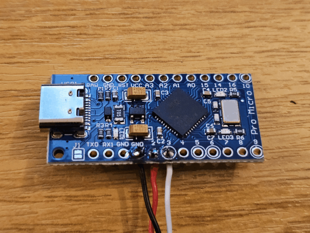
It is then fairly straightforward to make the 3 solder joints needed:
Black: GND
Red: A2 (dit)
White: A3 (dah)
You may have to tinker around with the connections a little bit to get your radio, the adapter and your key to work interchangeably. Above is what it ended up being for me.
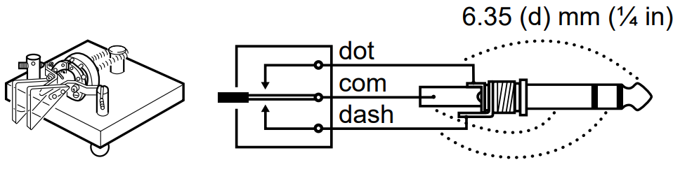
Above, taken from the manual of my Icom IC-7610. I have wired the Arduino to have the same polarity as the radio, assuming this to be the standard. Note, the radio uses a 6.35mm (1/4in) jack, not the smaller 3.5mm (1/8in) as we’re using.
And you’re ready to program the MCU! We’ll finish up with the hardware once we’ve checked it works!
Arduino Pro Micro Code
// Include the keyboard drivers
#include <Keyboard.h>

// Pin Definitions: Where the paddle pins connect.
// Note: Closing the contact should ground these pins.
# define DIT_PIN 2
# define DAH_PIN 3

// Arduino setup code
void setup() {
  pinMode(DIT_PIN, INPUT_PULLUP); // en internal pullup (dit)
  pinMode(DAH_PIN, INPUT_PULLUP); // en internal pullup (dah)
  Keyboard.begin(); // start keyboard runtime
}

void loop() {
  // While no paddle button is pressed, release all keys.
  while (digitalRead(DIT_PIN) == HIGH && digitalRead(DAH_PIN) == HIGH){
    Keyboard.releaseAll();
  }

  // On DIT pressed, send LEFT CONTROL key, else release
  if ( digitalRead(DIT_PIN) == LOW){
    Keyboard.press(KEY_LEFT_CTRL);
  } else{
    Keyboard.release(KEY_LEFT_CTRL);
  }

  // On DAH pressed, send RIGHT CONTROL key, else release
  if ( digitalRead(DAH_PIN) == LOW){
    Keyboard.press(KEY_RIGHT_CTRL);
  } else{
    Keyboard.release(KEY_RIGHT_CTRL);
  }

  // Wait 5ms
  delay(5);
}
Tidying it up!
Once you’re happy it is working as you wish, an optional step for longevity is to protect the PCB. I did this by first applying a dot of super-glue to the cable and attaching it to the back of the PCB (note how I brought the wires out on that side).
Next I used some heatshrink tubing to cover the board, protecting everything.
And, you’re good to go!
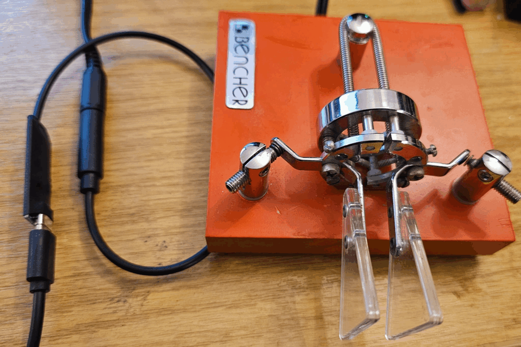
With that, you’re ready! Connect your key, connect your USB cable, and you can practice until you’re CW is perfect!
With Parks on the Air (POTA) becoming a relatively new thing in the UK, I decided to activate a few local parks. It quickly became apparent that many of the local parks had never been activated before. I decided that I would concentrate on those.
I suspect that they hadn’t been activated before because they required a bit of a walk to get to. What with it being winter and wanting to get out of the house, I kitted up my backpack with my Icom IC-705, my EcoWorthy 8Ah LiFePo4 battery (see my notes on IC705 power vs voltage) and a few antenna options. Over the course of a few evenings, heading to a different park each night after work, I activated the parks I had seen on the POTA App Map. I wanted a way to find any parks that were local, but that hadn’t been activated.
With services like SOTL.AS for Summits on the Air (SOTA), it’s easy to filter the map to only show specific things, like removing summits you’ve activated, or setting a minimum number of activator points, or showing only summits that haven’t been activated before. Unfortunately no such service exists for POTA (yet). If you’re reading this and considering doing something similar, check out SOTLAS first 🙂
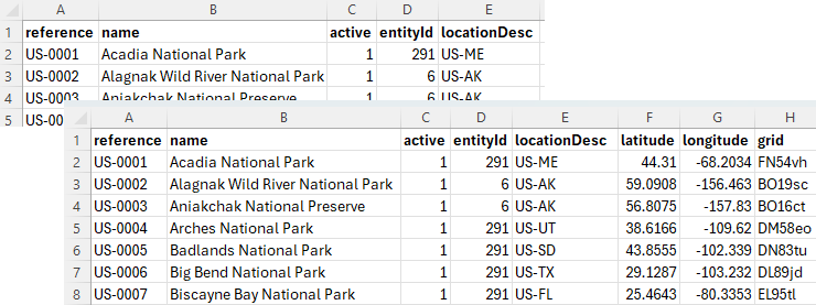
The POTA website does offer all_parks.csv (list of all POTAs) and all_parks_ext.csv (list of all POTAs with location information). However, neither of these files have the information I was looking for: the number of activations or attempted activations. Disappointing, but I didn’t give up that easily! I did some digging!
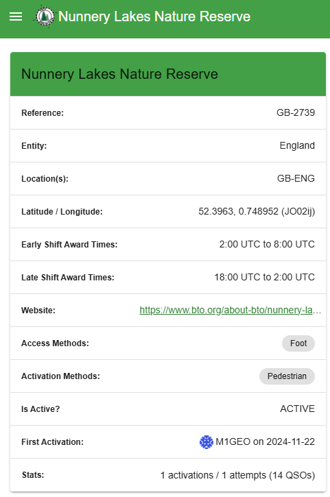
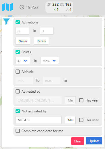
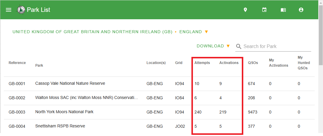
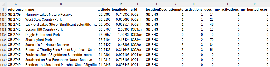
By searching the POTA ParkList for parks in my country, in my case “GB-ENG”, I was able to see the information I needed. At this stage, you could just sort the columns by activations, and skim through looking for close places. However, I wanted to do better than that! I wanted to create a program that would list them by how close they were to me.
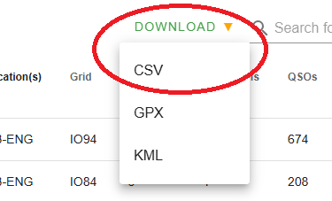
The observant amongst us will have noticed the “DOWNLOAD” button, that yields a CSV file for us. You may have to be logged in to see this, as it contains information personal to you (your activations, and hunts). I missed this the first time and subsequently copied and pasted the information manually from the webpage into a spreadsheet and exported it to a CSV which took about 5 minutes!
Regardless of how you chose to obtain the information, you’ll end up with a CSV file. Mine was called “England.csv”. The data inside is really useful and includes the latitude and longitude of each marker. Any program would just need to work out how far each site is from a given location (say, your home QTH) and then sort the output by distance. It could filter on attempts or activations, too.
The Program
So I set about writing a simple Python program (really more of a script) that lets you explore your POTA CSV file and (most importantly for me) find the closest unactivated POTA parks.
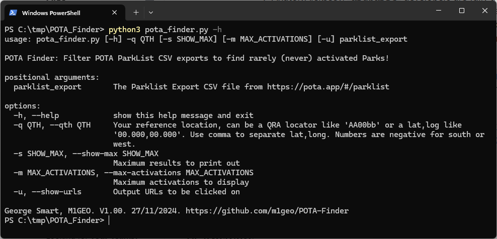
The code can be found on GitHub: https://github.com/m1geo/POTA-Finder. It runs in a command terminal window on any OS that will run Python3. It has a simple help function, and minimal error checking as it was an evening project. The source code should be easy enough to tinker with should you wish to add, change, remove functionality.
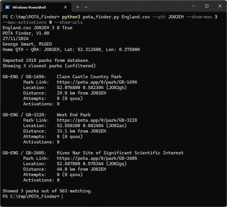
Calling the program with the -h help flag will output the above information to help you get started. You can set the --max-activations to 0 to show unactivated parks, like this:
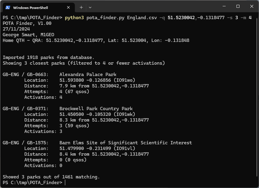
You can also use the shorter command-line options as below, and supply a lat/long as here:
And with that, you can pack your kit in the car and head out for a POTA activation…
In the summer of 2024 during a Camb-Hams trip to Friedrichshafen, I was drawn into the world of SOTA (summits on the air). A key requirement for SOTA activations is a compact, lightweight and effective station.
When I got started, I was able to use Rob M0VFC‘s Elecraft KX2 portable transceiver. However, from our third SOTA activation of the holiday I was taking my own Icom IC-705. My CW is not great, and so I was activating on SSB mainly on HF (and some FM on VHF/UHF). The IC-705 was a little easier than the internal microphone on the KX2. Rob M0VFC was kind enough to loan me use of his 3S LiPo battery, but I noted that as soon as the voltage dropped a little from full (4.2V * 3S = 12.6V), the IC-705 power was reduced considerably. This was also apparent on the KX2, but isn’t usually an issue because the SOTA pro’s use CW. Anyway, a challenge to know what I needed to do was born… I needed to understand how the IC-705’s RF output power changed as a function to the DC input voltage. I set up a simple test…
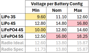
The radio specification states 13.8V ± 15%, which gives us an absolute voltage range of 11.73V (13.8V-15%) to 15.87V (13.8V+15%).
Setup & Method
The test setup was simple. My IC-705 connected to a high quality lab power-supply (Rigol DP821), accurate voltage and current readings for DC input power (two Keysight 34401A multi-meters) and a way to measure RF output power (Keysight N9010B spectrum analyser & 30dB attenuator).
The input voltage and current could be measured and adjusted in real time and the input power would be calculated for each test. The RF output power was measured at the frequency of interest.
During all testing the external battery was removed from the radio so that the battery charging current did not confuse measurement. To generate RF, the radio was set into RTTY mode at 100% power (thus creating a pure tone at full power). Each test was automated, and tested quickly to avoid heating issues in the PA.
Initial Results
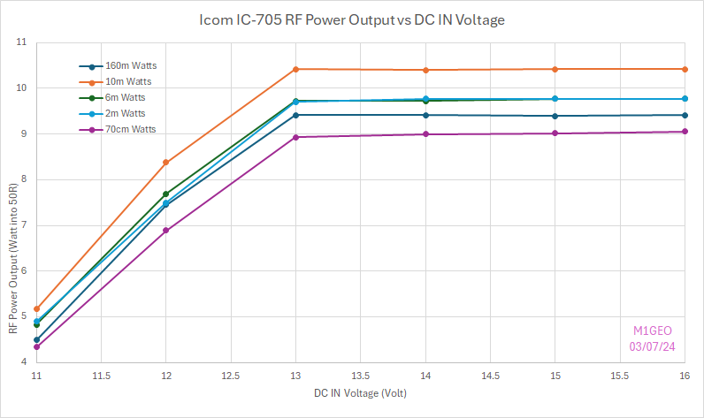
I measured things at both ends of HF (160m and 10m), and on 6m, 2m and 70cm. The results were consistent with the drop of output power I had noted. More importantly for the initial results, I could see that the behaviour was consistent across all bands, so I could concentrate testing on a single band, and take more detailed steps without creating extra work.
In every test, the power above 13V was very consistent, likely due to ALC on the PA. The efficiency slowly dropped as the input voltage increased. Below 13V, the power was observed to fall.
Further Testing
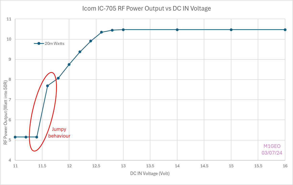
After the initial testing, I started digging a bit more into what happens between 11 and 13 Volts input. Working downwards from 13V there is a clear linear drop-off until around 11.8V where the software senses the falling voltage and drops to the 5W mode. At 11.6V the radio alternates between the 5W battery limit and the higher power (about 7.5W). This 11.73V threshold that the specification mentions (13.8V-15%).
For useful purposes, we need to keep the DC IN voltage above 11.8V (and below the maximum of 15.87V).
Battery Choices
Assuming we want to keep with a modern battery technology (so, excluding NiCd and NiMH), we have two obvious choices of lithium-ion battery:
Lithium Polymer (LiPo) battery
Lithium Iron Phosphate (LiFePO4) battery
For each battery pack, there are different combinations of series (S) and parallel (P) configurations, detailed using this “S” and “P” notation. For example, you may see a “3S4P”, referring to three series sets of four parallel batteries. Parallel-ing the batteries increases current handling and overall power, and the voltage is unchanged. Series-ing the batteries increases the voltage and overall power, but the current is unchanged.
Each battery technology has a different nominal voltage (the assumed cell voltage), charged voltage (the maximum cell voltage) and the discharge voltage (the minimum cell voltage). A battery will often have a BMS (battery management system) to take care of protecting the battery from over-charging, over-discharging, balancing (keeping the voltage across series cells equal), etc., but these are out of scope for this page.
LiPo
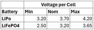
Typical Lithium Polymer (LiPo) cells have a nominal voltage of 3.7V. Fully charged, each cell is 4.2V. Fully discharged, each cell is 3.2V.
Typical Lithium Iron Phosphate (LFP, or more commonly LiFePO4) batteries have a nominal voltage of 3.2V. Fully charged, each cell is 3.65V. Fully discharged, each cell is 2.5V.
They have a higher cycle rating than standard LiPo batteries, meaning they can be charged and discharged more many more (>60% more) times before they start to fail.
I have tried to limit my choice to batteries that are widely known and in production. I have seen AliExpress selling Sodium-Ion batteries and other similarly novel battery technologies, but without easy access and known reliability, I didn’t include them.
From the IC-705 testing and the specification as well our two battery choices, we can see what options are available.
Extrapolating from the two battery types above, we can see that configurations in the right kind of area are as follows:
Unfortunately, there is no ideal solution with these battery technologies. It is kind of disappointing that Icom did not consider this when designing the radio – a small design tweak to take 17V would have allowed LiPo 4S battery packs to be used. Instead, the best option is LiFePO4 4S. However, as the battery discharges, the lower voltage becomes an issue.
From the tables above it is possible to see that the only real options are LiPo 3S and LiFePO4 4S since the other combinations have the ability to supply excessive voltage (>15.87V) to the radio. Of these two, the LiFePO4 4S has a higher maximum voltage (14.6V vs LiPo 3S at 12.6V). For this reason, the LiFePO4 4S is my preferred choice. LiFePO4 has the added advantage of a higher cycle count and increased safety too, so those are further marks on the LiFePO4 scorecard.
The voltage decision is made: LiFePO4 4S. Now for the capacity of the battery…
Battery Capacity
The 4S battery fixes the pack voltage to a nominal 12.8V. For the capacity, it’s just a case of estimating how much current the radio will draw and then using this to infer the battery capacity you require in “Amp-Hours”.
The IC-705 draws around 220mA (0.22A) in receive from the external power supply at 12.8V (our nominal LiFePO4 4S voltage). If we would like the radio to run on receive for an evening, say 6 hours, we’d need a battery to run 0.22A * 6h = 1.32Ah.
In reality a SOTA activation will be around 50% transmit (at ~2.1A) and 50% receive (at ~0.22A). However, the activation will probably be quite short, perhaps 30 minutes, perhaps 2 hours. By working out the average current used during an hour, an approximate runtime can be calculated for any battery or a battery capacity specified for a given desired operating period.
The final, and perhaps most important consideration for battery capacity is weight! The typical way to expand the current capability of the battery is to parallelise cells; which in effect means doubling the number of them – in our case, doubling or 4-series-connected cells, thus creating two interconnected strings of 4 cells, totalling 8 cells. This becomes a 4S2P battery pack as we discussed earlier. The capacity is doubled. But, so is the weight!
So, what did I buy?
In the end I bought a LiFePO4 4S1P battery made from 3Ah cells. This gives me a 12.8V nominal, 3Ah battery which will run the IC-705 on receive for around 13 hours, or a mix of SSB TX and receive for around 4 hours.
Feeling Brave? Try a LiPo 4S?
Shortly after writing this, I was on a discussion online and someone told me that they had run their IC-705 on a 4S LiPo pack for years and the radio had been fine. They mentioned that it stops charging the battery when the input voltage was above 16V (already out of spec) but that they had happily used 16.8V inputs (actually in excess of 17V) with no damage to the radio.
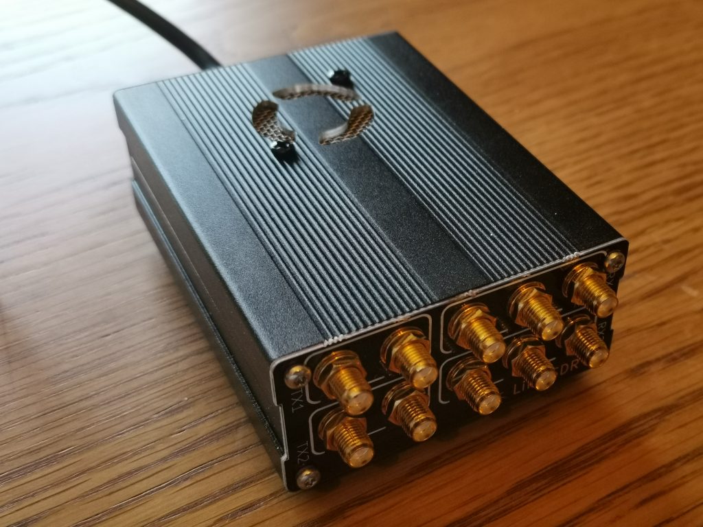
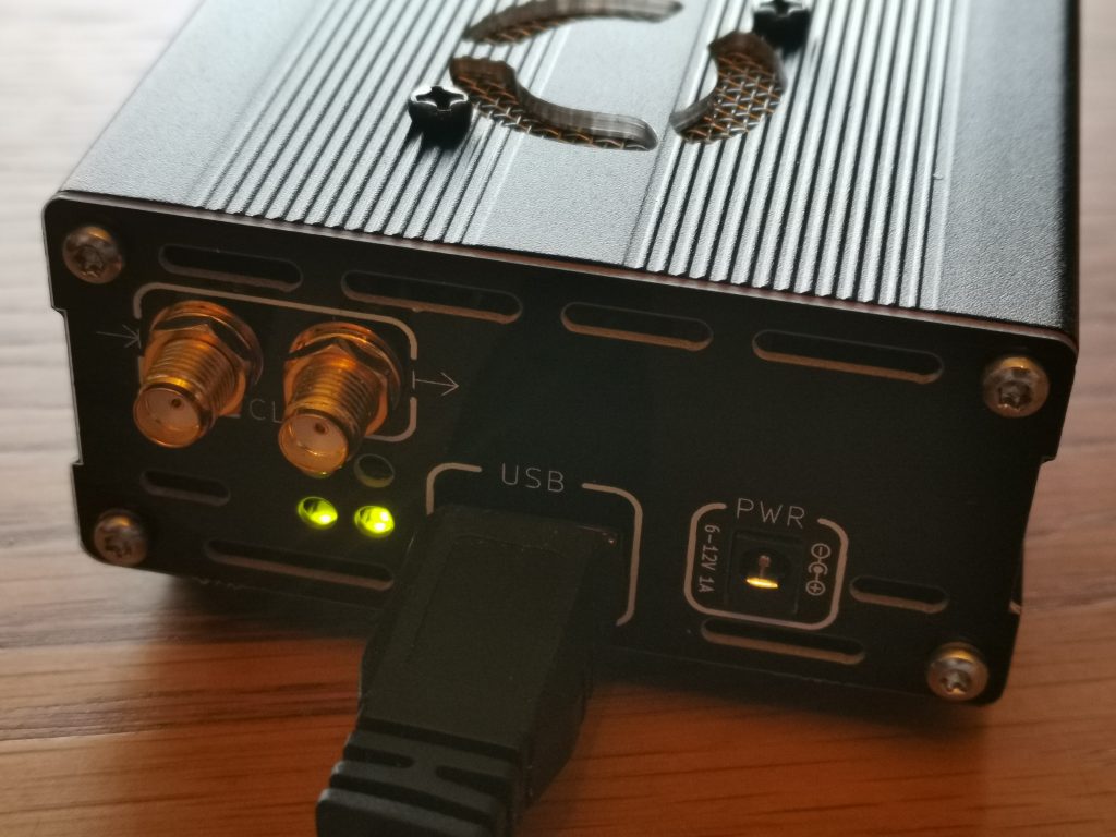
In a moment of madness, I tried 17V input and noted that (a) the IC-705 does stop charging the internal battery, (b) the HF noise floor was quieter (likely due to the battery charger powering off) and (c) that the radio didn’t explode and still delivered 10W. The radio’s voltage readout caps at 16V on the meter display and the voltage quick menu shows “Hi Voltage” instead of a number. See the two images below showing the difference at 16.9V input (from my 4S LiPo pack).
Maybe not the best thing to do long term, but it could help get you that that much needed QSO on a wet and windy SOTA…
Following on from my Receiving Es’Hail-2 GeoSat article, the obvious next thing to write something about transmitting. I created a draft of this article, but it seemed to mix heavily with the specifics of my station and was less generic. So I felt it better to create this page first, detailing my 2.4 GHz transmitting station, which I have just cobbled together in the time since writing the original article.
About the LimeSDR
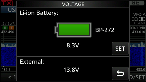
Let me first start by saying that I’ll be using a LimeSDR USB which has a continuous frequency range of 100 kHz to 3.8 GHz. Clearly acceptable for our requirements of 2.4 GHz. The bandwidth the SDR can support is staggering 61.44 MHz. The SDR is based around an Altera Cyclone IV FPGA with 256 MB of DDR2 RAM and a Rakon RPT7050A reference clock at 30.72 MHz. It has 6 inputs and 4 outputs, and boasts a CW transmitter power of up to +10 dBm (10 mW).
The RF sockets on the LimeSDR
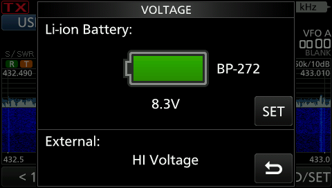
Clock and USB sockets on the LimeSDR
Clearly the LimeSDR is nothing without some fancy software to drive it; and there are plenty of good offerings. I decided to opt for SDRConsole V3 by Simon Brown G4ELI, which at the time of writing was version 3.0.5 (Feb 2019).
SDRConsole with the LimeSDR
The process of setting the LimeSDR up was easy. I had to collect the LimeSDR drivers for Windows and install those. That process is nicely described on the Miriad RF LimeSDR USB Driver Install page, but the crux of it is: (a) download the drivers from their GitHub page [direct link to master here], (b) use Device Manager to find the LimeSDR, and replace the driver with that in the zip.
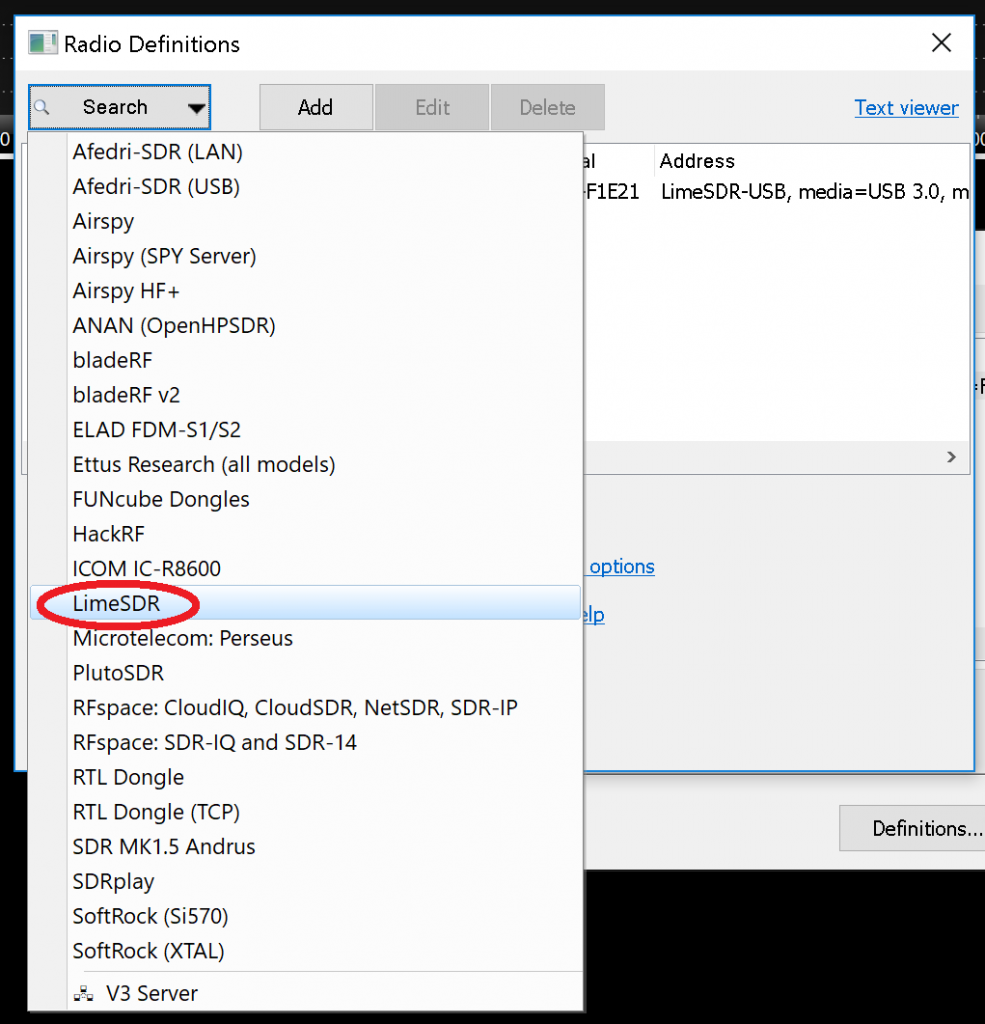
Once the driver is installed, you’re ready to set up SDRConsole. When the program starts, it will state that you do not have any radios defined, and give you the opportunity to define one. Simply select “Search” and then “LimeSDR” and it will find your radio. Accept the changes you’ve made.
Radio Definitions: Define your LimeSDR
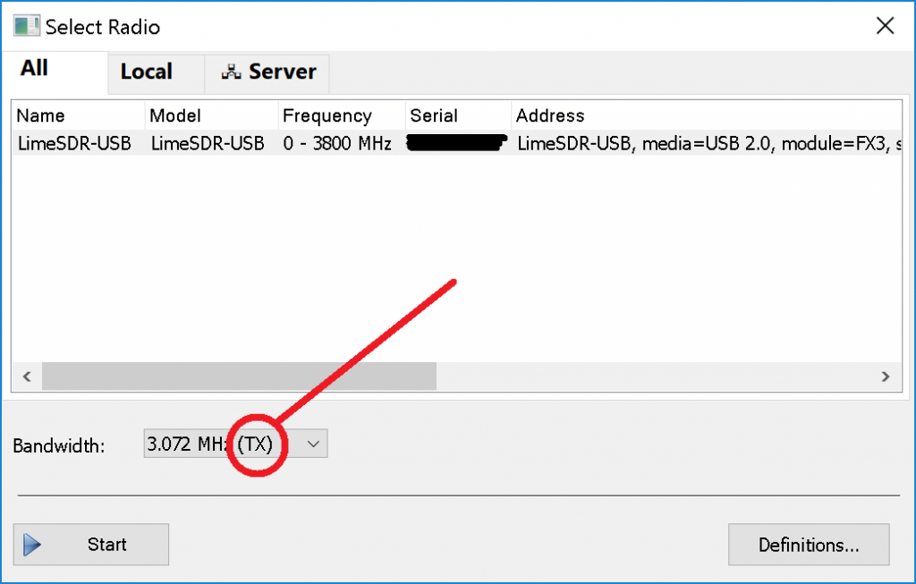
Once you have defined your radio, you should select it from the box that pops up following the definition (and subsequently each time you start SDRConsole). Select the LimeSDR you have just defined, make sure you select a bandwidth that supports transmitting “(TX)” in the “Bandwidth” option, and “Start” will become clickable in the bottom left. You should see the console spring to life.
Select Radio: Make sure you select a bandwidth what supports TX.
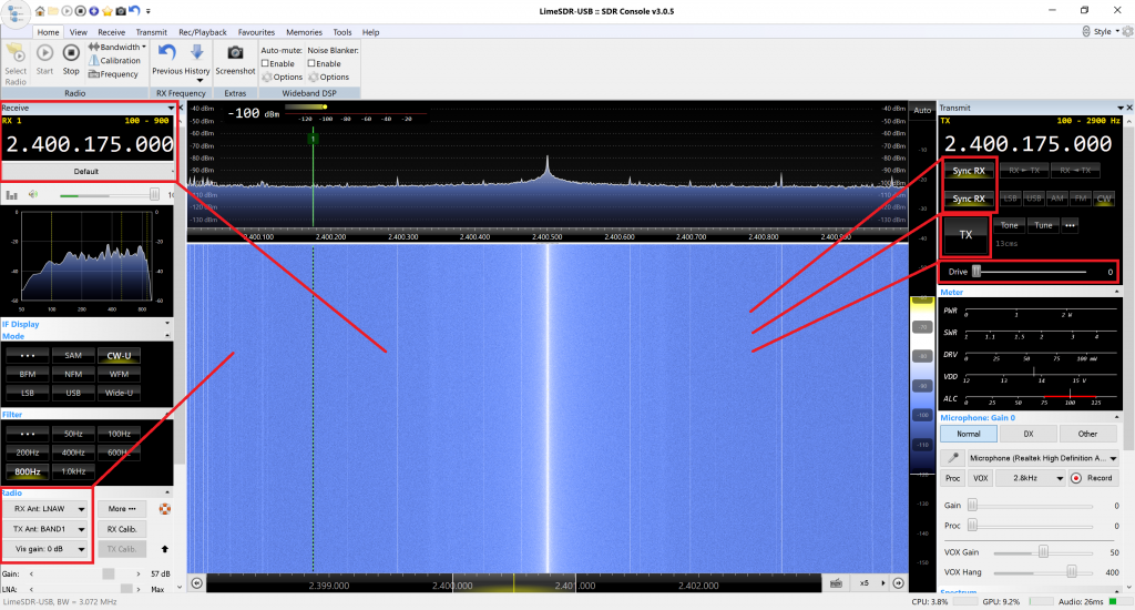
From the Receiving Es’Hail-2 GeoSat article, you will recall that the narrowband transponder input is 2400.050 MHz to 2400.300 MHz. Taking the middle of this band to be 2400.175 MHz. The screenshot below shows the radio on this frequency. I have put boxes and tails on some of the important settings.
From the figure above, you can see the receive frequency on the top left box, with the transmit frequency on the top right box. The “Sync RX” options for frequency and mode show that the TX frequency and more are locked to that of the receiver.
The “Drive” control on the top right box controls the RF power on the output and we shall try to characterise that later. Just above it is a “TX” button which causes the transmitter system to be engaged, and the receiver to be muted.
Finally, in the bottom left there are controls which select which of the LimeSDR’s 6 receive sockets and 4 transmit sockets are in use.
LimeSDR Output Power
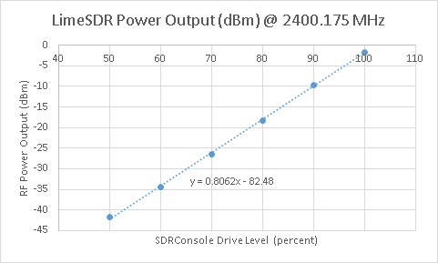
The next thing to do is measure the LimeSDR’s TX power on the frequency of interest: 2400.175 MHz, the centre of the NB transponder uplink. A CW signal is used to generate a constant power level.
To achieve this, I have used a known calibrated R&S NRP18A, which will measure power from 100 pW to 200 mW. We are expecting a maximum of 10 mW, so we should be easily safe to use this.
The drive level is a percentage, ranging from 0 to 100. My basic plan was to take a reading every 10%, and if there is a large non-linearity, I’ll take further measurements in those areas. At this point, the LimeSDR is only powered via the USB bus, and has no external power source. With drive levels below 50%, the reading was noisy, so I concentrated on the linear part of the curve.
Drive Level (%)
Power (dBm)
Power (mW)
50
-41.62
0.000069
60
-34.35
0.000367
70
-26.5
0.002239
80
-18.31
0.014757
90
-9.69
0.107399
100
-1.62
0.688652
Graph of LimeSDR output power vs drive level at 2400.175 MHz
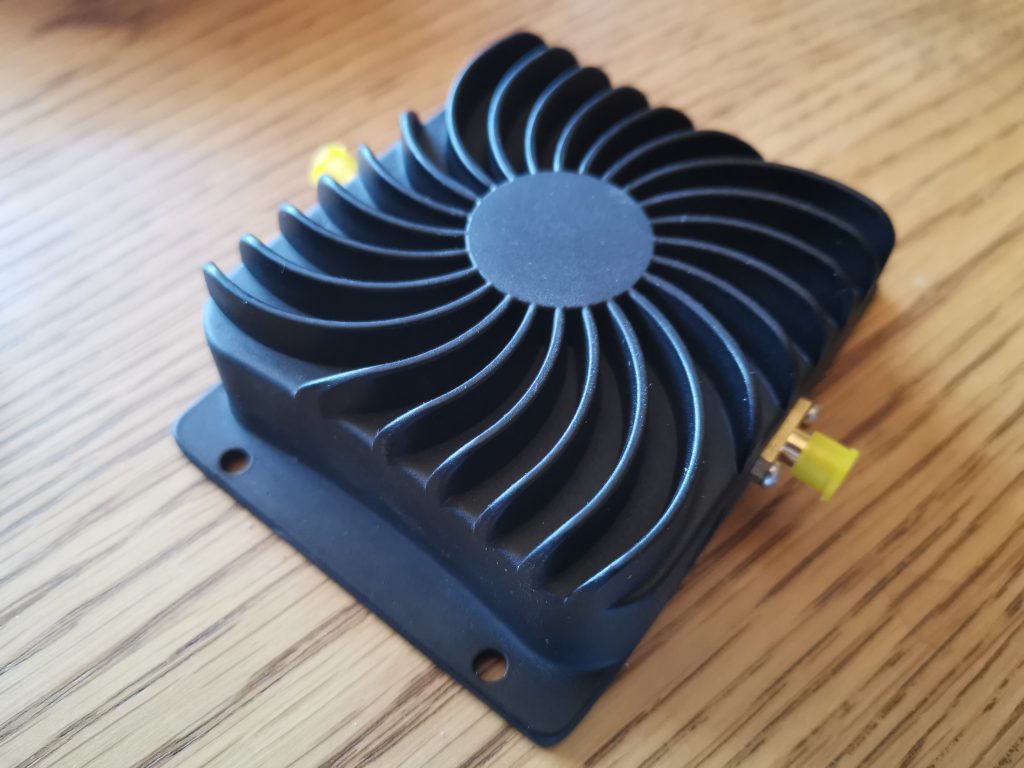
EDUP 8W WiFi Power Amplifier
I purchased an EDUP 8W WiFi power amplifier for £35 in February 2019 for use with the LimeSDR and Es’Hail-2 uplink. There had been talk on Twitter of these amplifiers being suitable, so I decided to give one a go.
EDUP 8W WiFi Amplifier cost around £35 delivered
Without getting into details, the amplifier has a system which detects if the WiFi radio is transmitting, and enables the PA’s TX path, or if the radio is receiving, and enables a separate RX path. This is exactly like “VOX” on an amateur radio amplifier. However, since the packets are very short on WiFi, with guard times in the order of 400 nanoseconds, the hang time is very short, and thus not suitable for SSB. We thus need to modify this behaviour, so that the amplifier is in TX all of the time, or, even better, when the LimeSDR is transmitting – perhaps using a GPIO pin to drive the amplifier – but that’s unimportant for now.
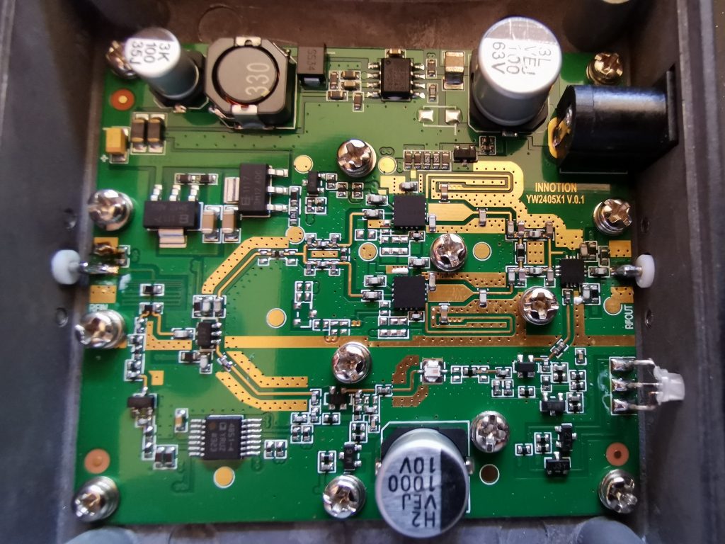
PTT Modification: EDUP 8W Amplifier
Here’s a snap of the insides of the amplifier. It’s clear that there is some room for improvement in gain with this amplifier, such as removing the (likely lossy) TX/RX switching, etc., as we don’t need these parts. However, for now, we’ll leave it. Swapping the RF-OUT RP-SMA connector for a standard SMA connector is probably a wise decision for the radio amateur.
Inside the EDUP 8W WiFi Amplifier
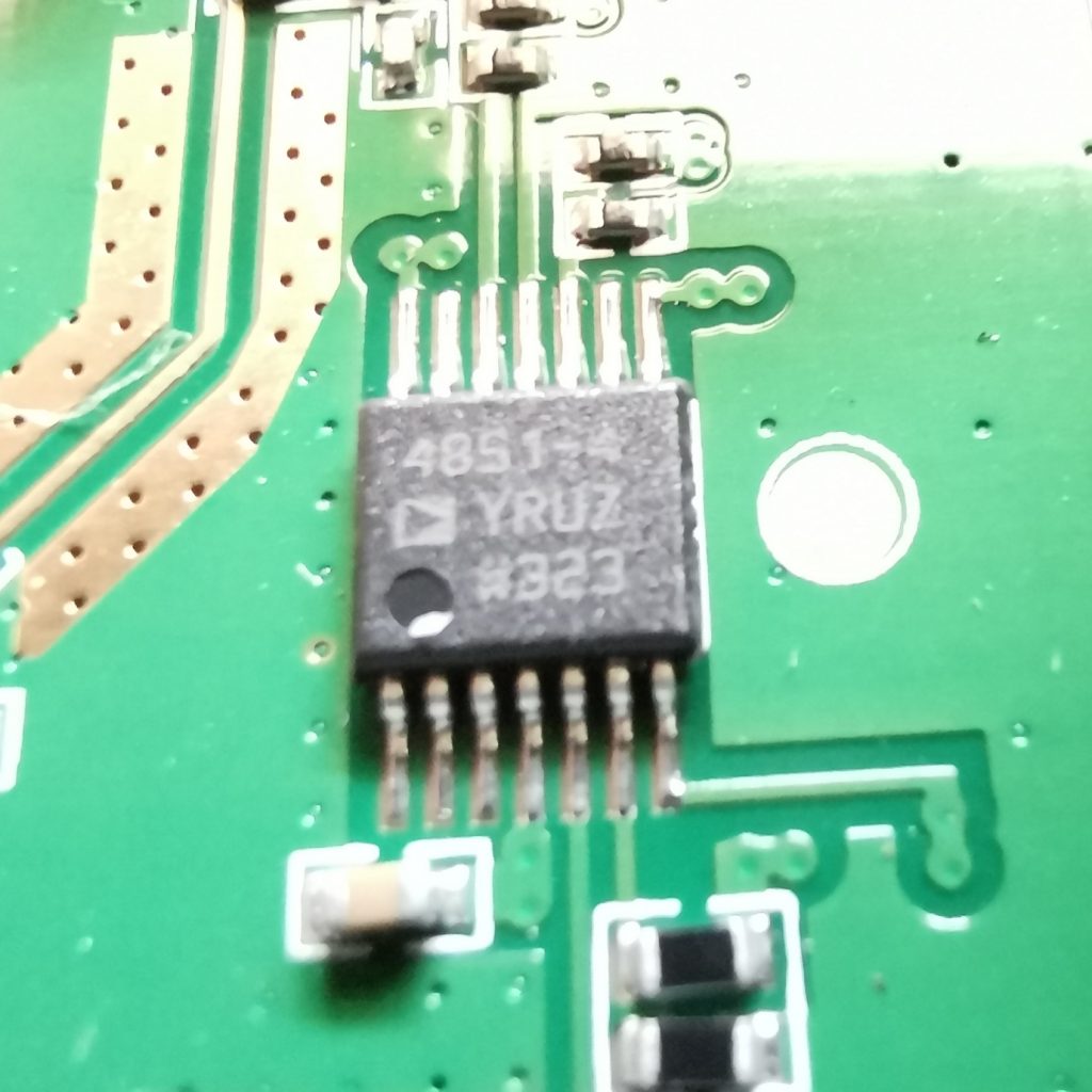
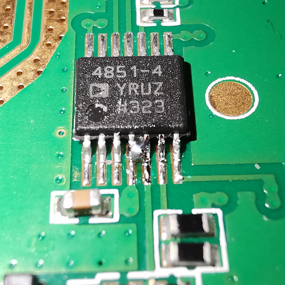
The mod, in its basic form, is just a solder bridge across pins 4 (VS) and 5 (+IN2) of the ADA4851-4 quad rail-to-rail op-amp on the opposite corner of the board to the DC power socket. The mod makes it appear that the diode detector is detecting a huge signal (5.787 V, the supply rail). The reference voltage (-IN2) is set at 0.189 V. When the voltage at +IN2 exceeds -IN2, the device enters transmit mode.
Before mod
After mod
If the amplifier is in receive mode, the status LED illuminates red. Conversely, if the amplifier is in transmit mode, the status LED illuminates green.
Measurements with the EDUP Amplifier
In terms of the experiment, the EDUP amplifier input is connected with an SMA barrel to the LimeSDR output, and the EDUP amplifier output is connected (via RP-SMA on the included short RG174 patch cable) to a 20 dB attenuator which in turn connects to the power meter.
Using this configuration, I do not expect that the output power will be come very high, since their is not enough drive level from the LimeSDR at −1.62 dBm. I see about 13 dB of gain, with an output of around +11dB (~10mW) of RF output power.
At this point the EDUP amplifier is drive limited. Working backwards, to achieve a theoretical +39 dBm (8 W) output, we would need to input +26 dBm (0.4 W) input.
The amplifier draws around 170 mA in receive, and about 380 mA in transmit with no RF (just quiescent bias).
More Gain!
Clearly connecting the EDUP directly to the LimeSDR does not provide enough power. There is a need for some more gain. Looking around what options are available cheaply, you quickly come across some options.
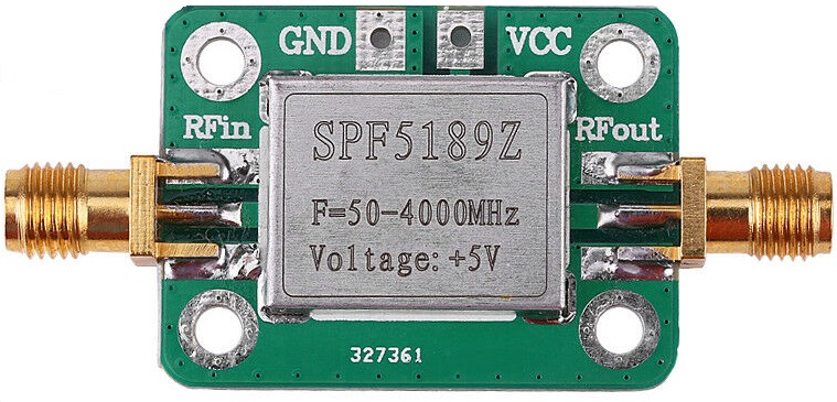
Qorvo SPF5189Z
SPF5189Z breakout module available from eBay, AliExpress, etc.
The Qorvo SPF5189Z has a small signal gain of 11.9 dB at 2.2 GHz (the closest listed frequency to the required 2.4 GHz) and an output P1dB of 22.7 dBm. This output power is close to the 26 dBm input required for the EDUP, although it is not recommended to run the system close to the 1 dB compression point (P1dB). With the SPF5189Z in line, we see approximately 20 dBm output (100 mW) from the EDUP.
Adding another SPF5189Z following the first gives around 30 dBm (1 W). Adding another 10 dB of gain early on in the drive chain will get us closer to the goal of 8 W output, but the system was becoming unwieldy and would probably not be suitable for use on air without inter-stage filtering as the parts used are wide-band.
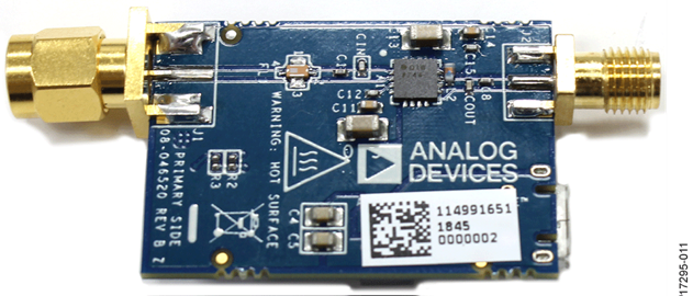
Analog Devices CN0417 Evaluation Board
Analog Devices CN0417 Evaluation Board (bottom side) [source]
Another part brought to my attention by @Manawyrm on Twitter is the Analog Devices CN0417 evaluation board (EVAL-CN0417-EBZ). It is a USB Powered 2.4 GHz RF Power Amplifier, and can be purchased for around £26 ($35 USD).
I have not used this part yet, but I know that others have with some success. The EVAL-CN0417-EBZ is based on the ADL5606 is a broadband, two-stage, 1 W RF driver amplifier which operates over a frequency range of 1800 MHz to 2700 MHz.
Nearly there…
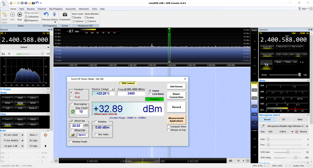
With some tidying of the interconnects, I was able to get to 32.98 dBm (1.95 W). More filtering will be required before letting this loose on air.
Screenshot of SDRConsole with RF Power Meter inset. +32.89 dBm = 1.95 W
Getting it on air!
At this point I was pretty keen to see if I could make it to the Es’Hail-2 satellite. The day I tried, 2 March 2019, followed an announcement by AMSAT that the narrowband transponder gain had been reduced, so I was keen to
AMSAT-DL reduced the transponder gain by several decibels on 28/02/2019
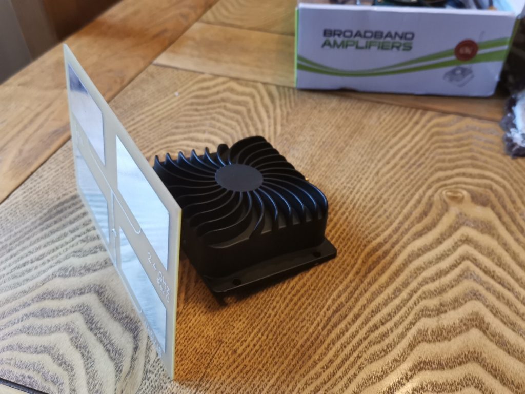
Balancing the amplifier and patch antenna on the back of a large reclining chair in the garden, I was able to align the patch antenna to the satellite’s location. Setting the TX frequency of the LimeSDR to the centre of the transponder band (2400.175 MHz), with an output power of around 1W of I was able to hear a single tone through the Es’Hail-2 narrowband transponder, I quickly added a CW paddle and was able to confirm my signal by sending “M1GEO TEST” several times, listening via the BATC NB WebSDR as discussed in my Receiving Es’Hail-2 GeoSat article.
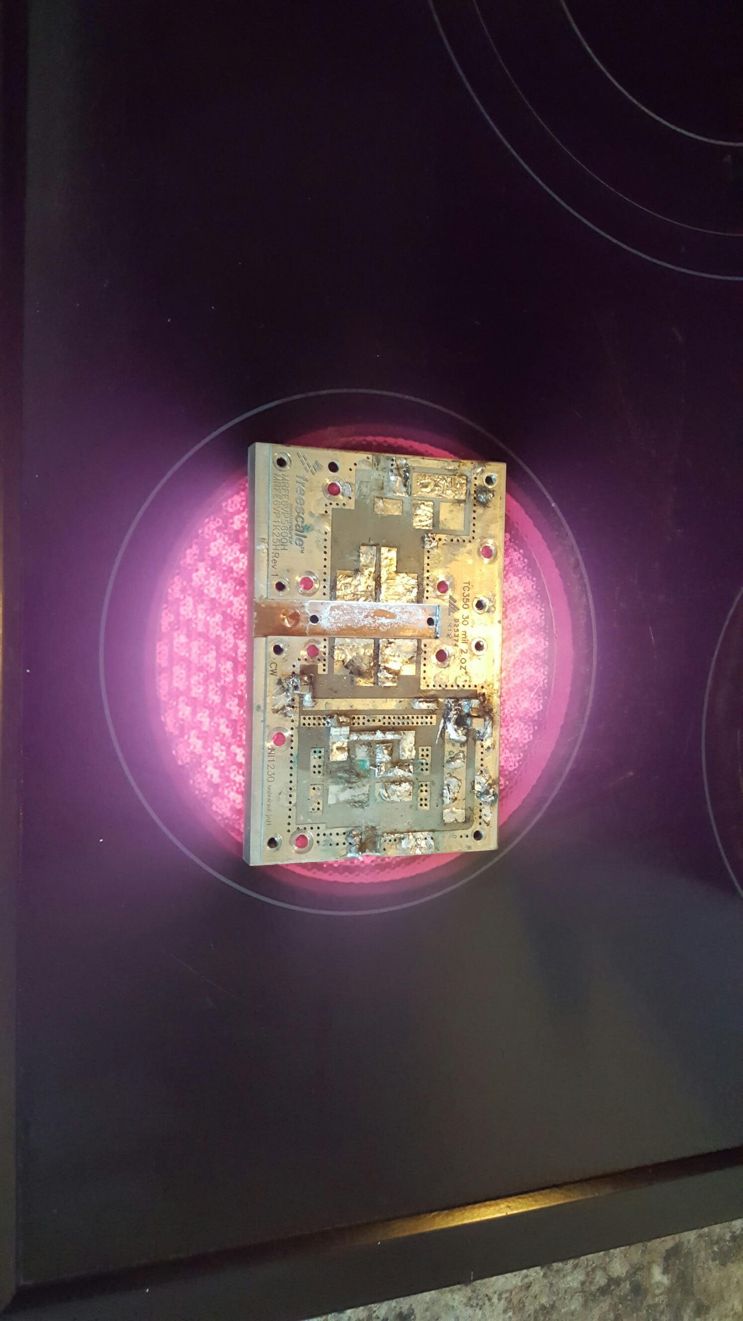
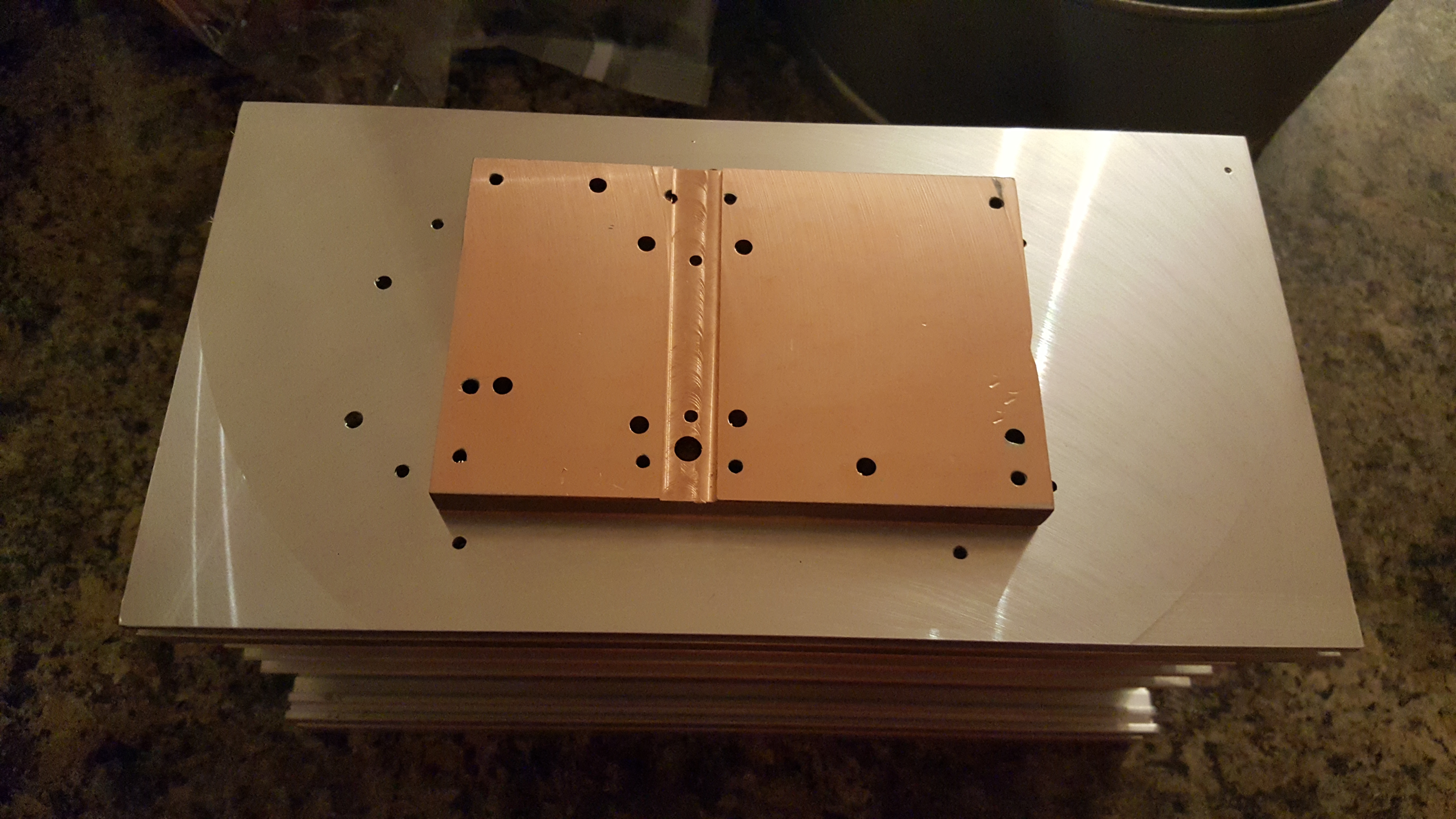
Back at the 2012 Friedrichshafen Hamfest I brought a 1.25 kiloWatt VHF amplifier kit for 144 MHz from F1JRD and F5CYS. These devices were fairly new at the time. It took me a year to pluck up the courage to build the pallet, but I went about it all wrong. With the help of Dad and the kitchen hob, we soldered the jrd1 Teflon PCB to the C110 copper heat-spreader as suggested in the Dubus article (see here). I had the pallet working at the time, giving around 600W of RF, which was about the maximum my 1000W 50V PSU was capable of sustaining. When I came to boxing the device up into an amplifier to use with EME and Meteor Scatter in late 2016, the part failed under test.
After much deliberation, I have ordered parts to repair the amplifier project. I found Jim W6PQL‘s website (see here) a wealth of information, and Jim also offers to supply parts and designs to help others. I ordered a set of PCBs to replace the original jrd1 board, a NXP/Ampleon BLF188XR 1400W part to replace the failed the Freescale/NXP MRFE6VP61K25H 1250W part, and some other accessories that Jim sells. The parts were posted by Jim today, so I decided it was time to recover parts from the old PCB and recondition the heatsink and heat-spreader.
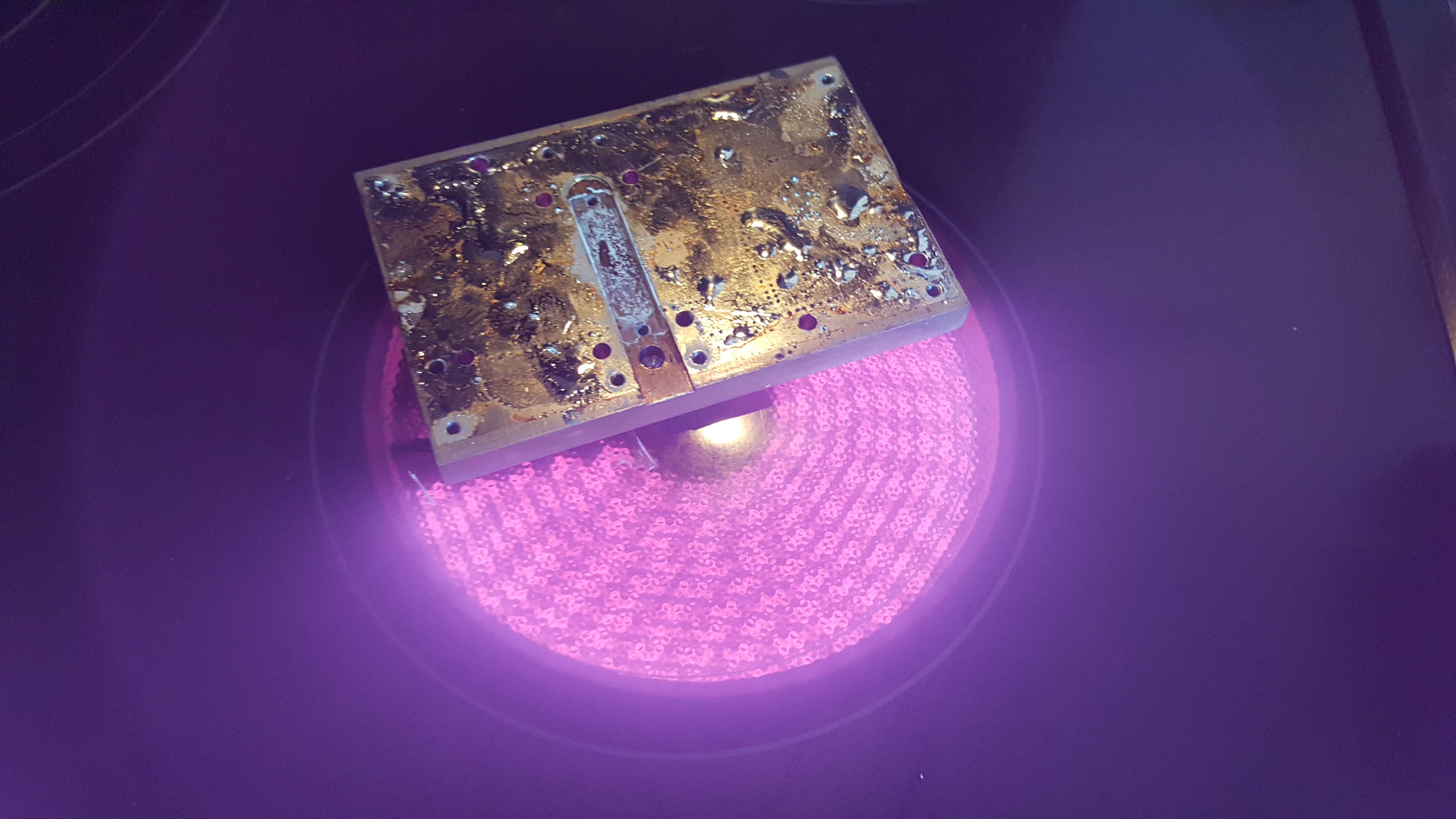
The first step was to remove the jrd1 board from the copper heat-spreader. I used the kitchen hob to heat the copper heat-spreader, since the old board was soldered to the copper block. The board damage was sustained to enable the removal of the more expensive components.
Below, the heat-spreader with the jrd1 board removed. I used a solder sucker and scraper to remove as much of the molten solder.
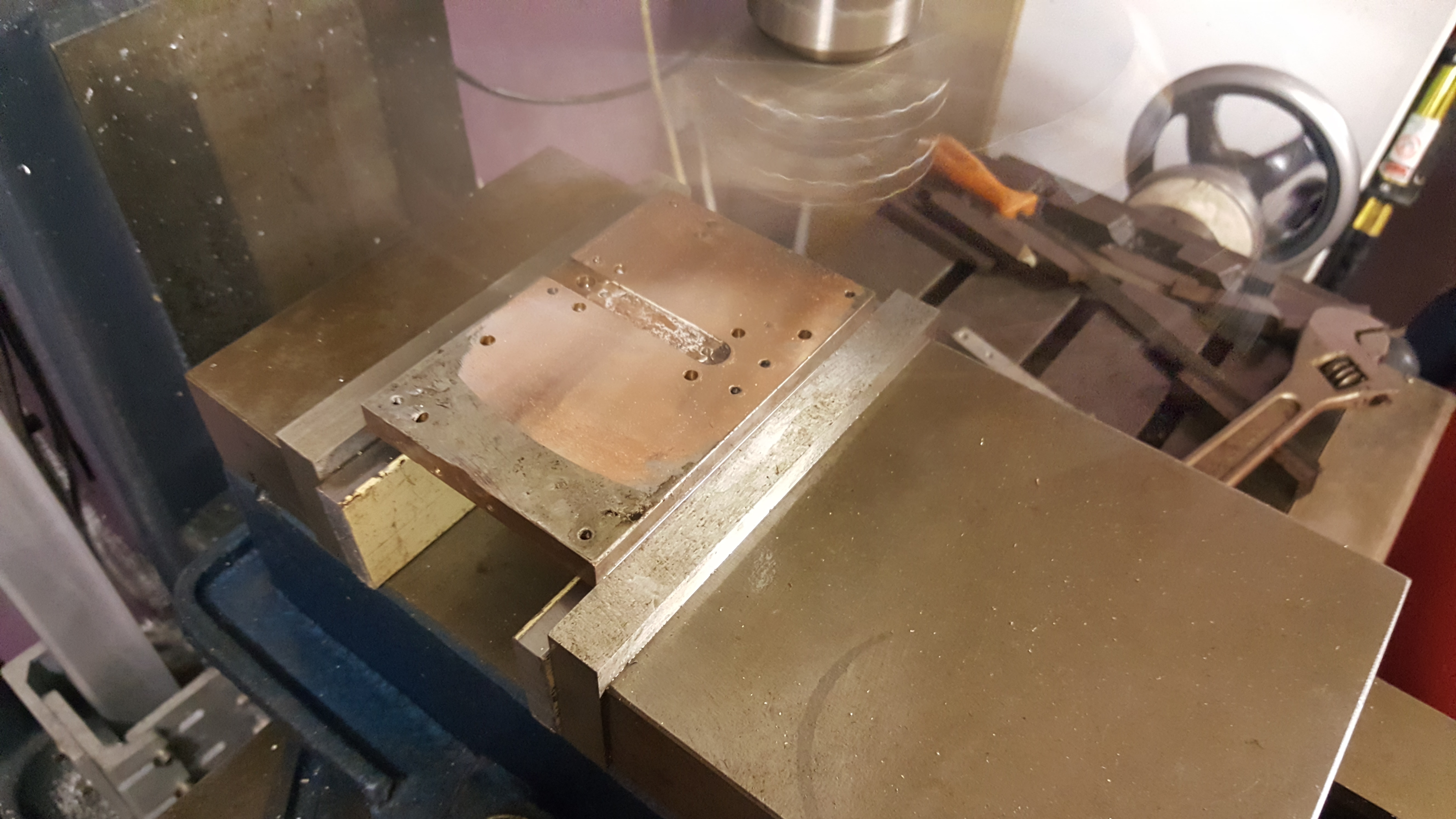
Once the heat-spreader had cooled down, I mounted the copper spreader up in the milling machine read to re-machine the top and bottom surfaces. Great care was taken to level the block using parallels. Below you can see the fly-cutting process on the first cut, removing just 0.05mm from the surface.
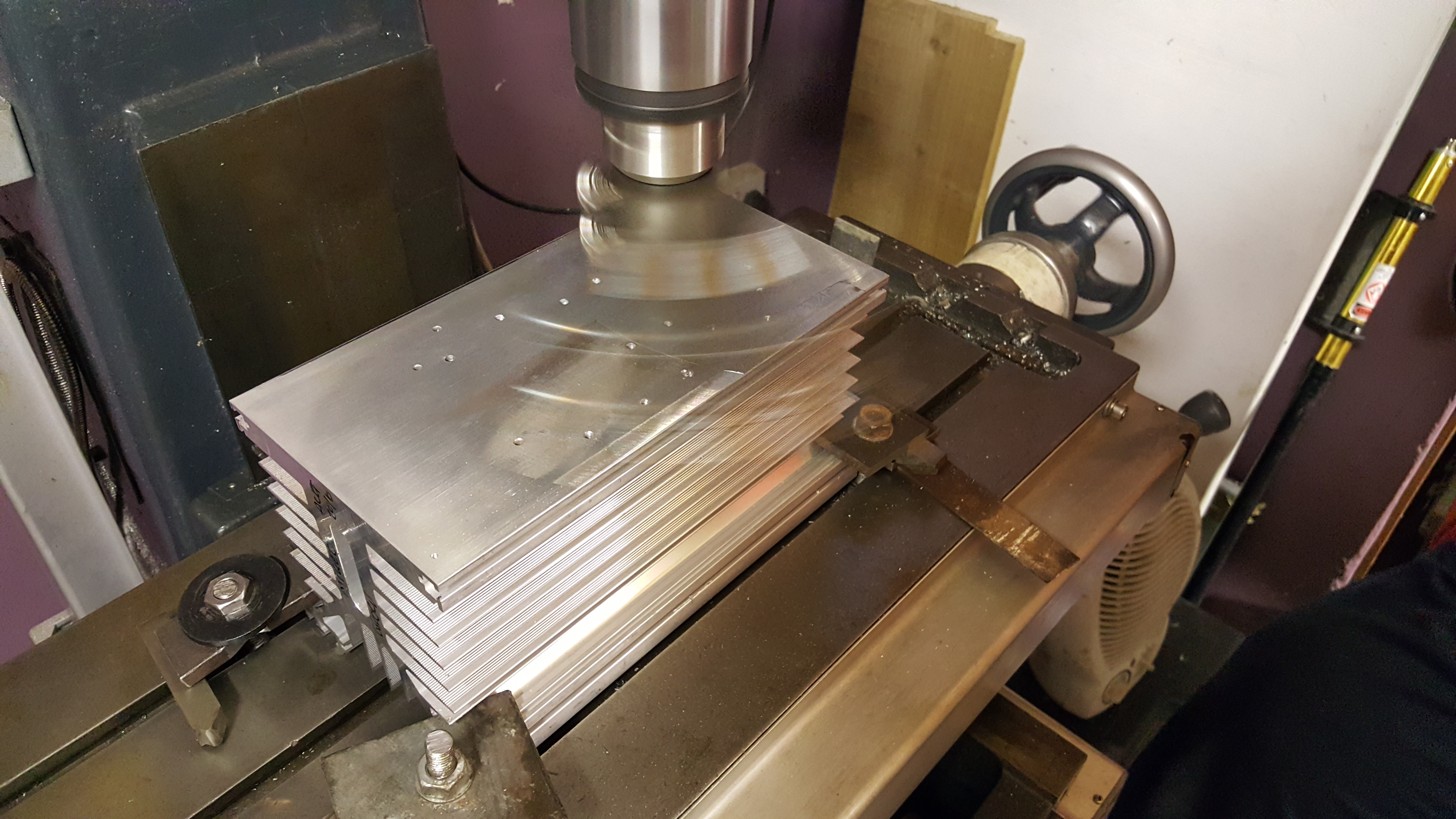
With the top and bottom of the head-spreader machined flat, a small end-mill cutter was used to machine the transistor slot to the correct depth following the skimming of the top surface. Then the heatsink mating surface was machined. Below you see the first cut on the heatsink.
The finished parts. A few machining marks, but the surfaces are perfectly good enough. Some dents on the copper block, but it’s not worth removing all of the material to eliminate these. Using a few drips of water as a substitute for thermal compound, the two mating surfaces stick together very well (with a good vacuum forming). That’s more than good enough for my needs!
Now I just need to wait for the parts to arrive before I can finalise the PCB and transistor mounting! This story continues here: Soldering Expensive Transistors.
After drying out from the RSGB IOTA contest last weekend, we took the gear out again 1-2 August, where I worked a few new contacts: 7Q7BP on CW was a firm favourite, as well as KH6/AA1LC in Hawaii, CY0/VA1AXC on Sable Is., 8P6FX in Barbados and CP6XE in Bolivia.
During the weekend we turned our hand towards the RSGB low-power backpackers contest working a few on 2m. After the contest, HA6KVC/P was coming through nicely via Meteor Scatter on FSK441.
This was the first time I have ever heard any meteor scatter… Ever…
Having attended a short talk by Steve M0SHQ at Essex Ham about operating Amateur Satellites, and seeing Steve work the ISS via APRS, I decided to have a go myself. I built the dual-band beam he recommended several times, but the design always measured up poorly. In the end I tweaked the design somewhat, and come up with something myself – it’s all credit to the original designer, I just optimised it with some antenna modelling software. Details on the antenna can be found here: Dual Band Satellite Yagi.
Today my Icom IC-7000 and associated separation kit sold on eBay. I have wrapped them up for posting. I’ll be sad to see the IC7000 go, since it’s been my main workhorse for a long time – It’s been everywhere, that radio; from the university office to touring around Europe! I’ve replaced it with the IC7100 for DSTAR use, as well as an IC7700 (which I have had for a while).
Another batch of QSL cards arrived this morning for M1GEO, MQ1GEO and MO1GEO. I had unfortunately run out so I have ordered another batch of my own cards. They will take a week or so to arrive. I’ll get them out as soon as I can. I also ordered another batch for GB0SNB too, while I was at it!
An online scrapbook full of half-baked projects and silly ideas.