
Following on from my Receiving Es’Hail-2 GeoSat article, the obvious next thing to write something about transmitting. I created a draft of this article, but it seemed to mix heavily with the specifics of my station and was less generic. So I felt it better to create this page first, detailing my 2.4 GHz transmitting station, which I have just cobbled together in the time since writing the original article.
About the LimeSDR
Let me first start by saying that I’ll be using a LimeSDR USB which has a continuous frequency range of 100 kHz to 3.8 GHz. Clearly acceptable for our requirements of 2.4 GHz. The bandwidth the SDR can support is staggering 61.44 MHz. The SDR is based around an Altera Cyclone IV FPGA with 256 MB of DDR2 RAM and a Rakon RPT7050A reference clock at 30.72 MHz. It has 6 inputs and 4 outputs, and boasts a CW transmitter power of up to +10 dBm (10 mW).
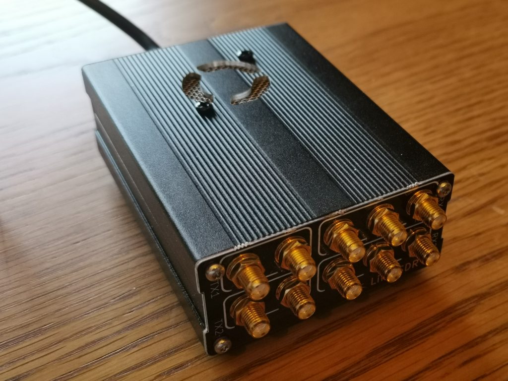
The RF sockets on the LimeSDR 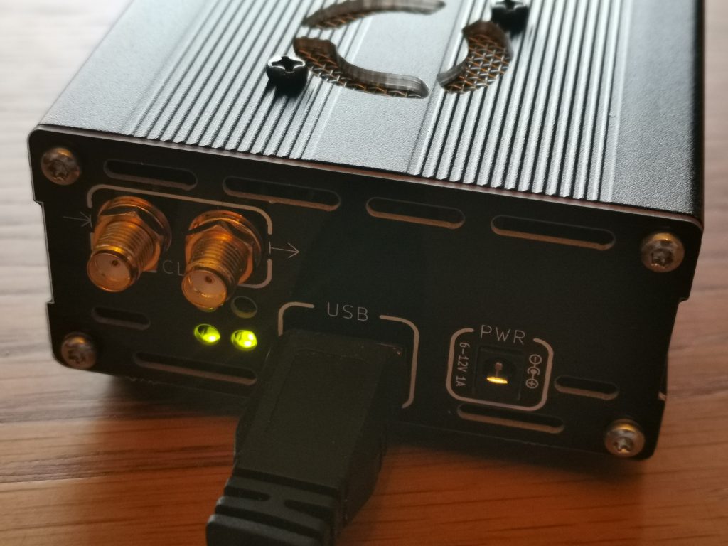
Clock and USB sockets on the LimeSDR
Clearly the LimeSDR is nothing without some fancy software to drive it; and there are plenty of good offerings. I decided to opt for SDRConsole V3 by Simon Brown G4ELI, which at the time of writing was version 3.0.5 (Feb 2019).
SDRConsole with the LimeSDR
The process of setting the LimeSDR up was easy. I had to collect the LimeSDR drivers for Windows and install those. That process is nicely described on the Miriad RF LimeSDR USB Driver Install page, but the crux of it is: (a) download the drivers from their GitHub page [direct link to master here], (b) use Device Manager to find the LimeSDR, and replace the driver with that in the zip.
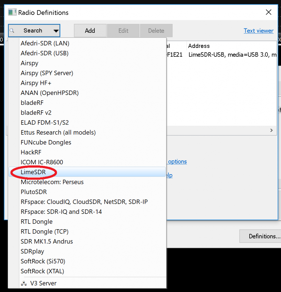
Once the driver is installed, you’re ready to set up SDRConsole. When the program starts, it will state that you do not have any radios defined, and give you the opportunity to define one. Simply select “Search” and then “LimeSDR” and it will find your radio. Accept the changes you’ve made.
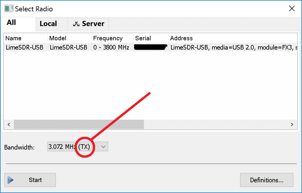
Once you have defined your radio, you should select it from the box that pops up following the definition (and subsequently each time you start SDRConsole). Select the LimeSDR you have just defined, make sure you select a bandwidth that supports transmitting “(TX)” in the “Bandwidth” option, and “Start” will become clickable in the bottom left. You should see the console spring to life.
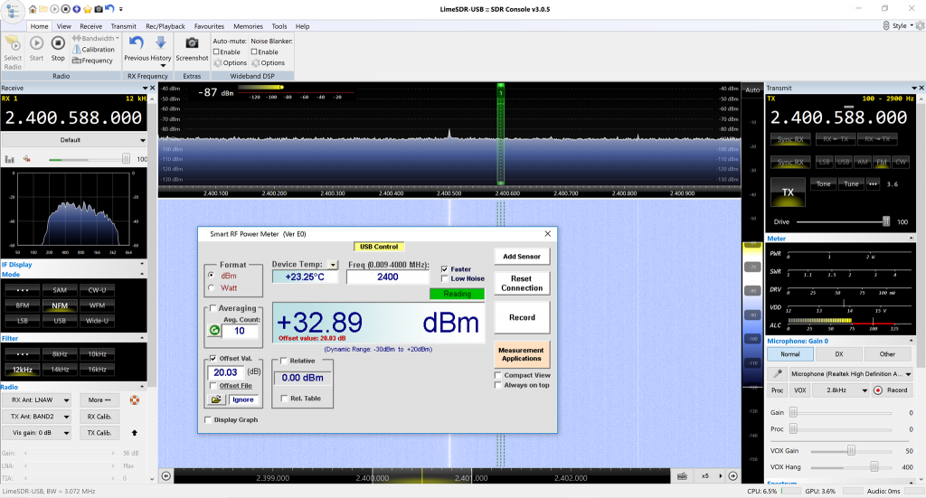
From the Receiving Es’Hail-2 GeoSat article, you will recall that the narrowband transponder input is 2400.050 MHz to 2400.300 MHz. Taking the middle of this band to be 2400.175 MHz. The screenshot below shows the radio on this frequency. I have put boxes and tails on some of the important settings.
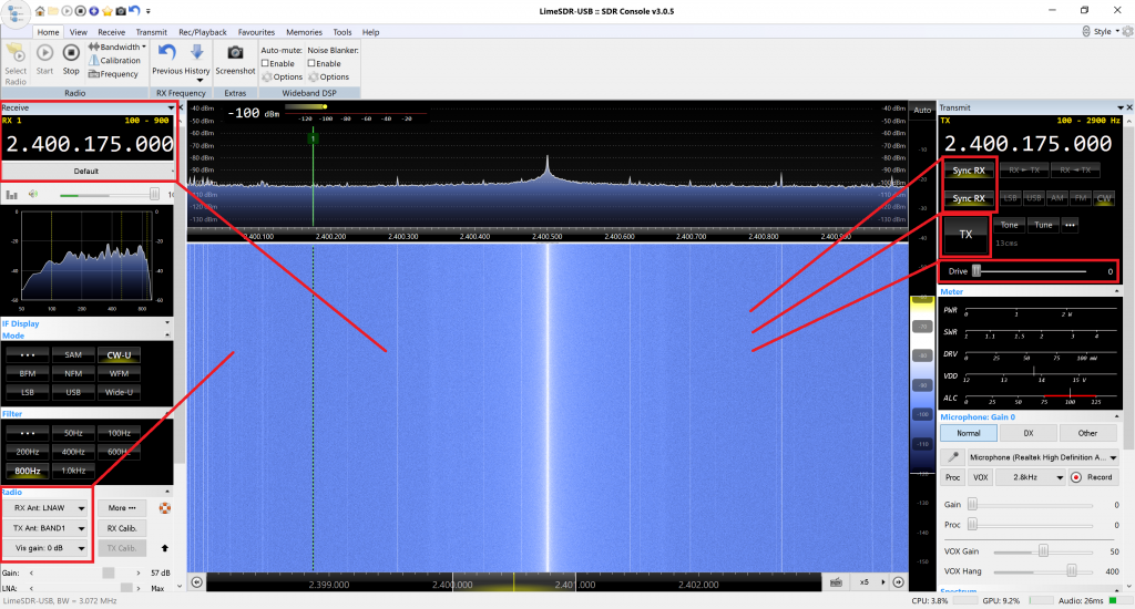
From the figure above, you can see the receive frequency on the top left box, with the transmit frequency on the top right box. The “Sync RX” options for frequency and mode show that the TX frequency and more are locked to that of the receiver.
The “Drive” control on the top right box controls the RF power on the output and we shall try to characterise that later. Just above it is a “TX” button which causes the transmitter system to be engaged, and the receiver to be muted.
Finally, in the bottom left there are controls which select which of the LimeSDR’s 6 receive sockets and 4 transmit sockets are in use.
LimeSDR Output Power
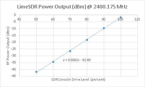
The next thing to do is measure the LimeSDR’s TX power on the frequency of interest: 2400.175 MHz, the centre of the NB transponder uplink. A CW signal is used to generate a constant power level.
To achieve this, I have used a known calibrated R&S NRP18A, which will measure power from 100 pW to 200 mW. We are expecting a maximum of 10 mW, so we should be easily safe to use this.
The drive level is a percentage, ranging from 0 to 100. My basic plan was to take a reading every 10%, and if there is a large non-linearity, I’ll take further measurements in those areas. At this point, the LimeSDR is only powered via the USB bus, and has no external power source. With drive levels below 50%, the reading was noisy, so I concentrated on the linear part of the curve.
| Drive Level (%) | Power (dBm) | Power (mW) |
| 50 | -41.62 | 0.000069 |
| 60 | -34.35 | 0.000367 |
| 70 | -26.5 | 0.002239 |
| 80 | -18.31 | 0.014757 |
| 90 | -9.69 | 0.107399 |
| 100 | -1.62 | 0.688652 |
EDUP 8W WiFi Power Amplifier
I purchased an EDUP 8W WiFi power amplifier for £35 in February 2019 for use with the LimeSDR and Es’Hail-2 uplink. There had been talk on Twitter of these amplifiers being suitable, so I decided to give one a go.
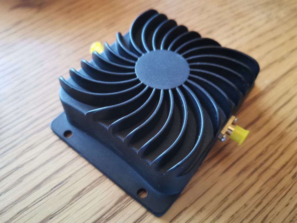
Without getting into details, the amplifier has a system which detects if the WiFi radio is transmitting, and enables the PA’s TX path, or if the radio is receiving, and enables a separate RX path. This is exactly like “VOX” on an amateur radio amplifier. However, since the packets are very short on WiFi, with guard times in the order of 400 nanoseconds, the hang time is very short, and thus not suitable for SSB. We thus need to modify this behaviour, so that the amplifier is in TX all of the time, or, even better, when the LimeSDR is transmitting – perhaps using a GPIO pin to drive the amplifier – but that’s unimportant for now.
PTT Modification: EDUP 8W Amplifier
Here’s a snap of the insides of the amplifier. It’s clear that there is some room for improvement in gain with this amplifier, such as removing the (likely lossy) TX/RX switching, etc., as we don’t need these parts. However, for now, we’ll leave it. Swapping the RF-OUT RP-SMA connector for a standard SMA connector is probably a wise decision for the radio amateur.
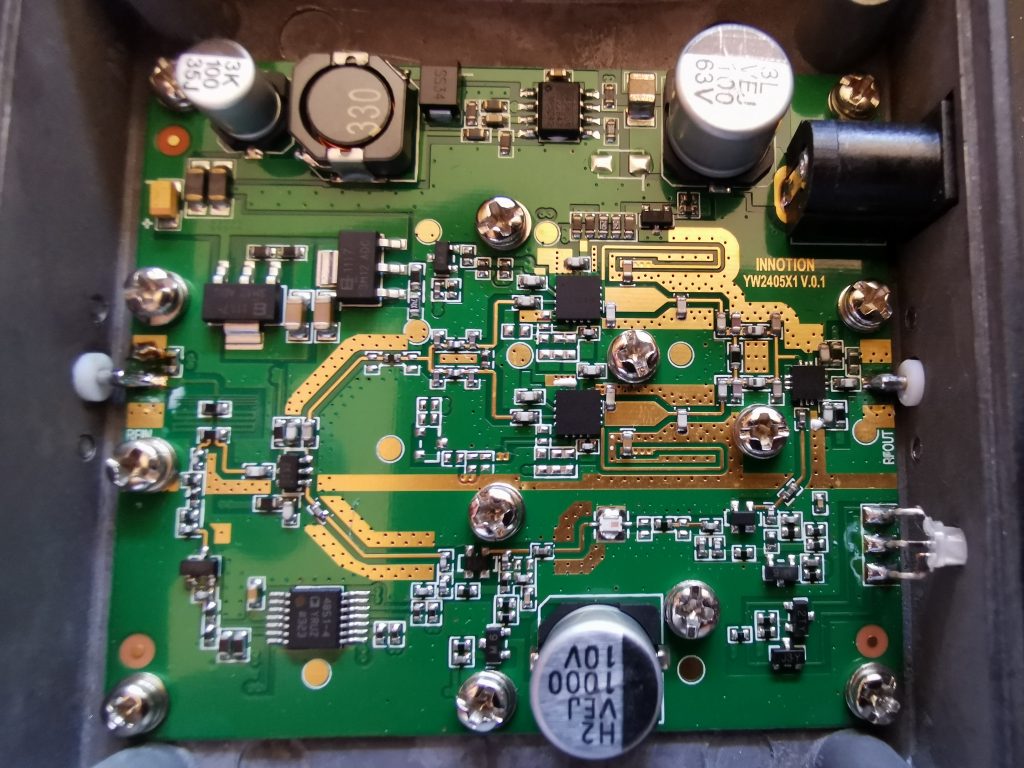
The mod, in its basic form, is just a solder bridge across pins 4 (VS) and 5 (+IN2) of the ADA4851-4 quad rail-to-rail op-amp on the opposite corner of the board to the DC power socket. The mod makes it appear that the diode detector is detecting a huge signal (5.787 V, the supply rail). The reference voltage (-IN2) is set at 0.189 V. When the voltage at +IN2 exceeds -IN2, the device enters transmit mode.
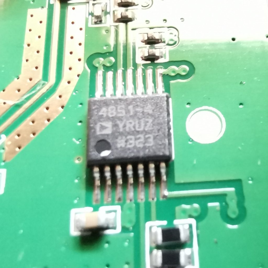
Before mod 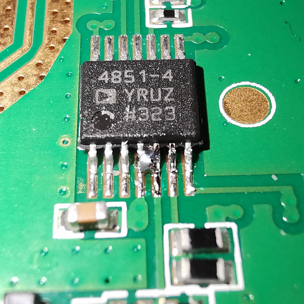
After mod
If the amplifier is in receive mode, the status LED illuminates red. Conversely, if the amplifier is in transmit mode, the status LED illuminates green.
Measurements with the EDUP Amplifier
In terms of the experiment, the EDUP amplifier input is connected with an SMA barrel to the LimeSDR output, and the EDUP amplifier output is connected (via RP-SMA on the included short RG174 patch cable) to a 20 dB attenuator which in turn connects to the power meter.
Using this configuration, I do not expect that the output power will be come very high, since their is not enough drive level from the LimeSDR at −1.62 dBm. I see about 13 dB of gain, with an output of around +11dB (~10mW) of RF output power.
At this point the EDUP amplifier is drive limited. Working backwards, to achieve a theoretical +39 dBm (8 W) output, we would need to input +26 dBm (0.4 W) input.
The amplifier draws around 170 mA in receive, and about 380 mA in transmit with no RF (just quiescent bias).
More Gain!
Clearly connecting the EDUP directly to the LimeSDR does not provide enough power. There is a need for some more gain. Looking around what options are available cheaply, you quickly come across some options.
Qorvo SPF5189Z
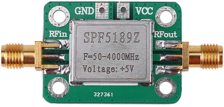
The Qorvo SPF5189Z has a small signal gain of 11.9 dB at 2.2 GHz (the closest listed frequency to the required 2.4 GHz) and an output P1dB of 22.7 dBm. This output power is close to the 26 dBm input required for the EDUP, although it is not recommended to run the system close to the 1 dB compression point (P1dB). With the SPF5189Z in line, we see approximately 20 dBm output (100 mW) from the EDUP.
Adding another SPF5189Z following the first gives around 30 dBm (1 W). Adding another 10 dB of gain early on in the drive chain will get us closer to the goal of 8 W output, but the system was becoming unwieldy and would probably not be suitable for use on air without inter-stage filtering as the parts used are wide-band.
Analog Devices CN0417 Evaluation Board
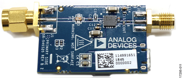
Another part brought to my attention by @Manawyrm on Twitter is the Analog Devices CN0417 evaluation board (EVAL-CN0417-EBZ). It is a USB Powered 2.4 GHz RF Power Amplifier, and can be purchased for around £26 ($35 USD).
I have not used this part yet, but I know that others have with some success. The EVAL-CN0417-EBZ is based on the ADL5606 is a broadband, two-stage, 1 W RF driver amplifier which operates over a frequency range of 1800 MHz to 2700 MHz.
Nearly there…
With some tidying of the interconnects, I was able to get to 32.98 dBm (1.95 W). More filtering will be required before letting this loose on air.
Getting it on air!
At this point I was pretty keen to see if I could make it to the Es’Hail-2 satellite. The day I tried, 2 March 2019, followed an announcement by AMSAT that the narrowband transponder gain had been reduced, so I was keen to
Using a WA5VJB quad-patch antenna purchased from Sam G4DDK, I was able to get going sooner than if I had held out to wait for the dual-feed solution that Mike G0MJW and others had been working on. The patch can be seen connected to the amplifier with a simple SMA barrel connector.
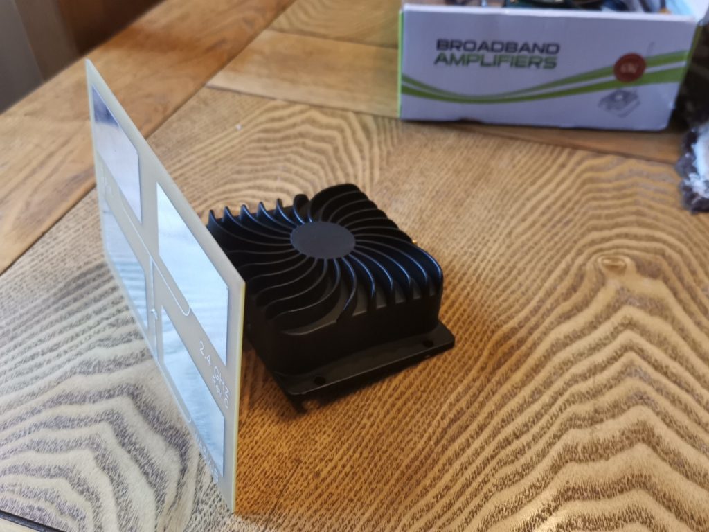
Balancing the amplifier and patch antenna on the back of a large reclining chair in the garden, I was able to align the patch antenna to the satellite’s location. Setting the TX frequency of the LimeSDR to the centre of the transponder band (2400.175 MHz), with an output power of around 1W of I was able to hear a single tone through the Es’Hail-2 narrowband transponder, I quickly added a CW paddle and was able to confirm my signal by sending “M1GEO TEST” several times, listening via the BATC NB WebSDR as discussed in my Receiving Es’Hail-2 GeoSat article.
I took a short recording using the BATC WebSDR:
Some filtering?
W1GHZ has a nice study on pipe-cap filters and there are other articles that describe their construction such as KO4BB Pipe Cap Filters construction page. Other options include inter-digital filters and similar.
Not much to report here… I still have some experimentation to do.
Where next?
The next article in this set describes making a dual-band feed. It is still being written…