All the project files are in the Build Notes section at the end…
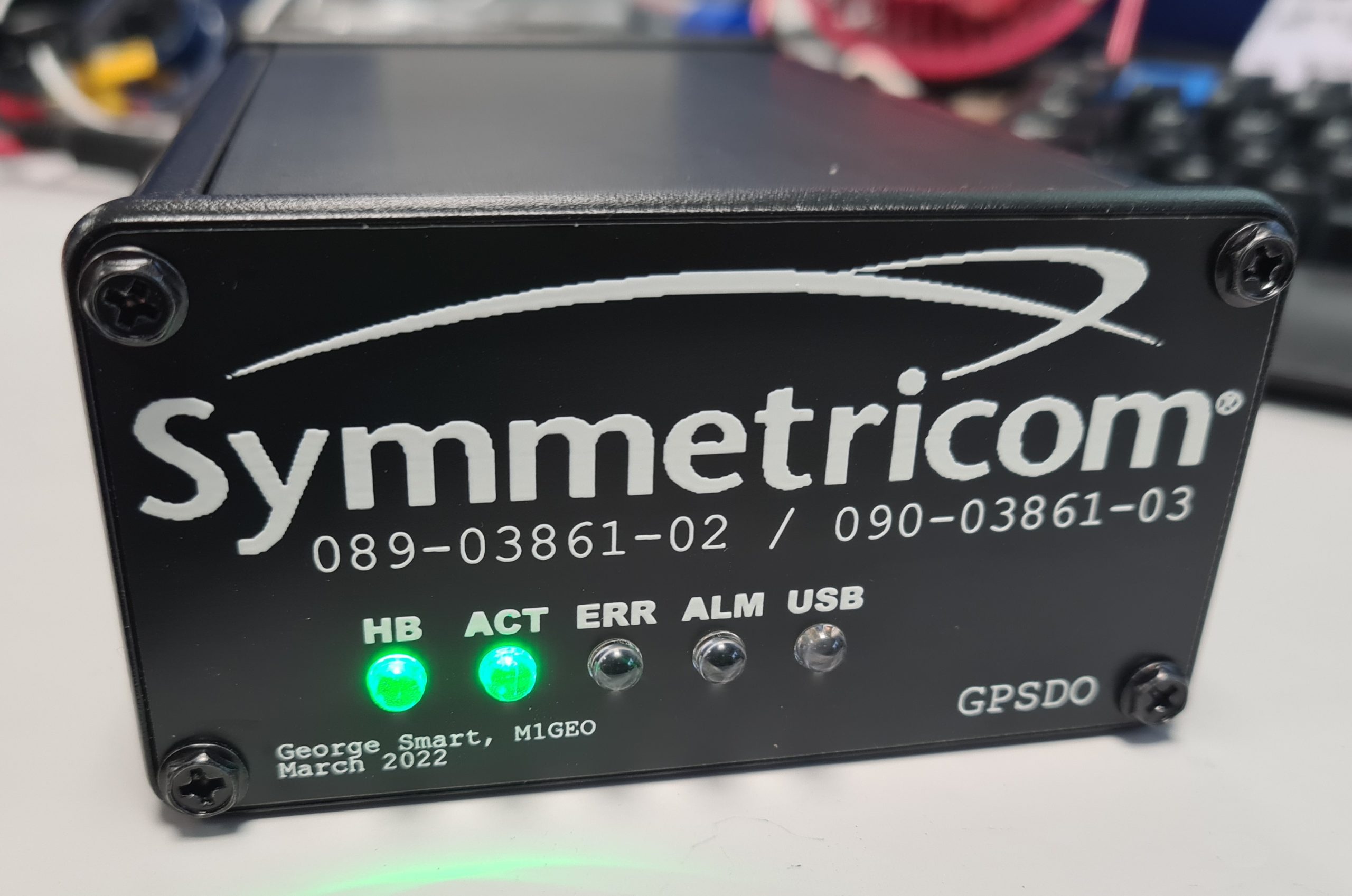
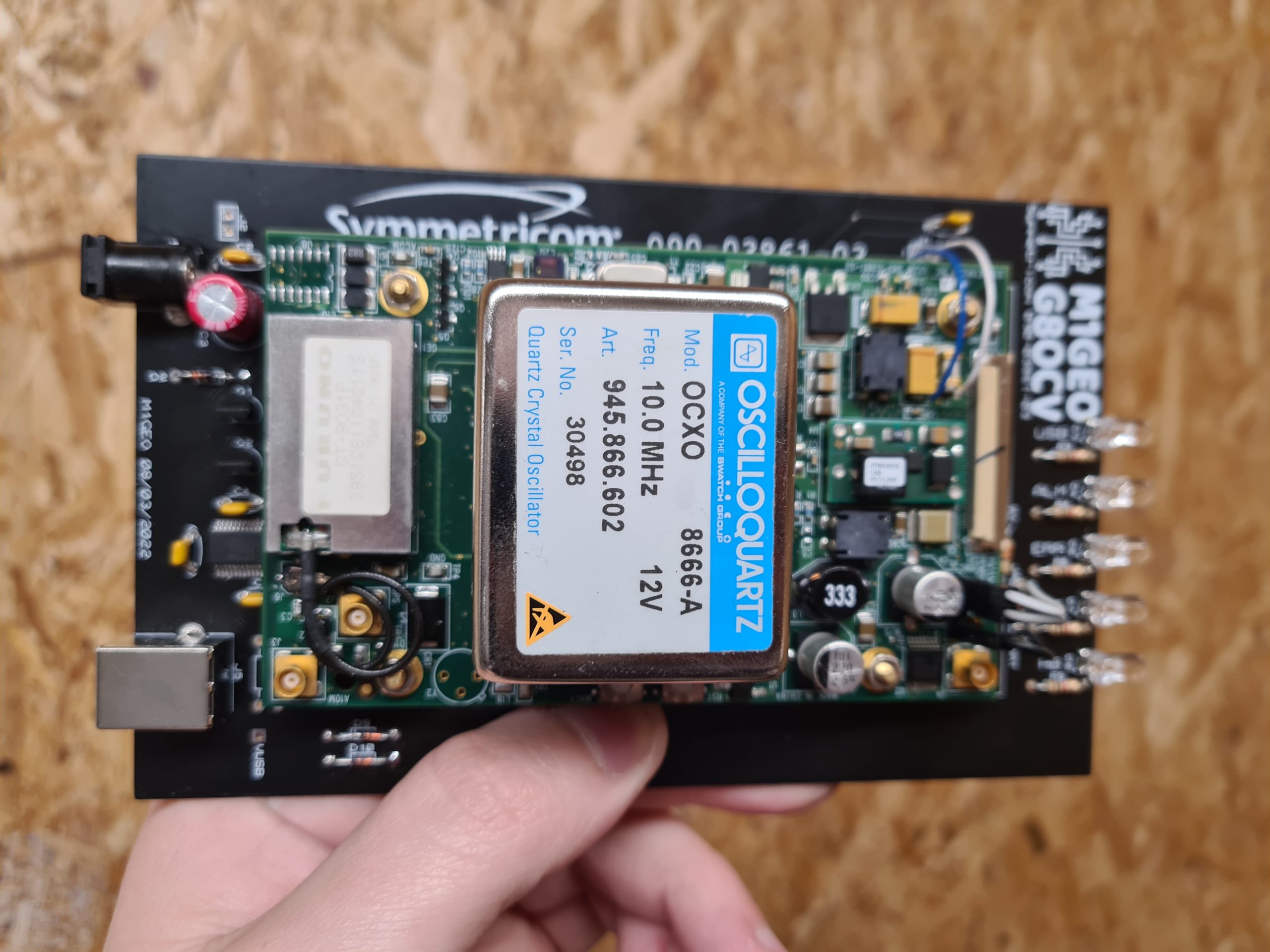
While tinkering with a homebrew GPSDO project, I spent a bit of time searching the depths of the internet for information and parts for my project. I found a PCB for a Symmetricom GPSDO (specifically the Symmetricom 089-03861-02 as per the PCB silkscreen in my case, although the firmware reports itself as 090-03861-03). The board was cheap because the OCXO was missing – I suspect it had aged beyond where the error voltage range was specified, making it unusable. But the board was around £15 GBP delivered from AliExpress, so I took a chance on it based on the fact it had a Furuno GT-8031F GPS receiver which is a GPS module specifically designed for timing applications which “delivers highly accurate GPS timing”. The module also had a CPU (Renesas F2317VTE25V-H8S/2317) with accompanying flash and RAM ICs as well as a Xilinx Spartan-3 FPGA (XC3S200).
Besides the missing OCXO module, my board worked perfectly. I was able to piece most of the information together from the following two resources:
- EEVBlog: A look at my Symmetricom GPSDO / 10MHz reference (OCXO + Furuno receiver)
- Trimble/Symmetricom UCCM GPS Receiver 50-pin connector pinouts and protocol reverse-engineering
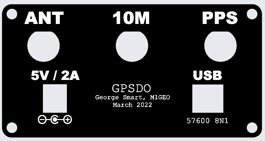
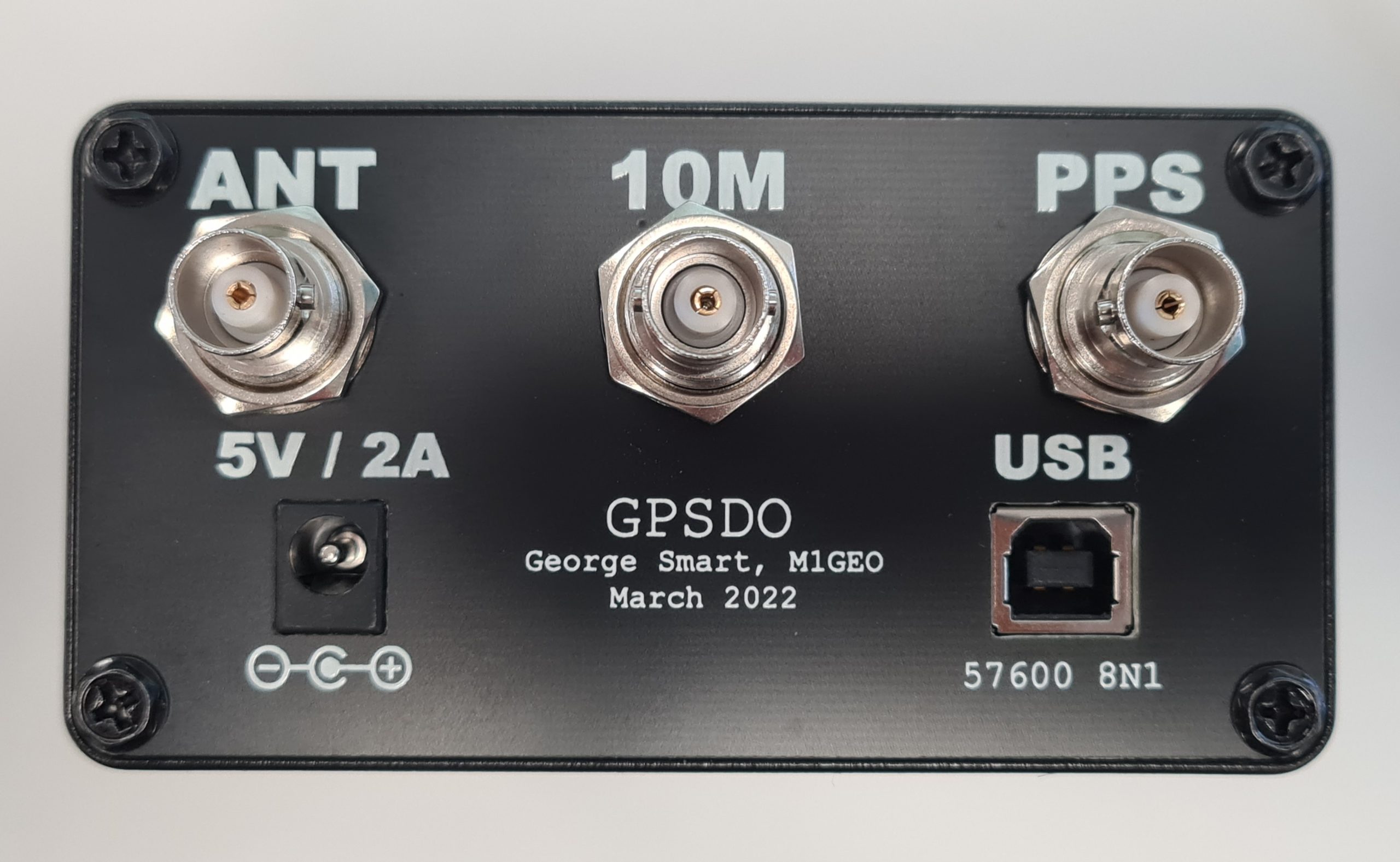
I saw that some people had put their units into Hammond Manufacturing project boxes, and that gave me a few ideas. It would be nice to box the unit up with some ancillary electronics to share the UART (57600 baud, 8N1) over Ethernet TCP/IP. However, my experience of UART to Ethernet modules has always been poor and friends reported similar, so I opted for an FTDI-based USB interface (namely the FT232RL, as the cheapest/easiest part during the chip shortage of 2019-2022). I was tempted to use a Maxim MAX232 device to perform the necessary conversions, but, in the end opted for two NPN transistors – a bit hacky, but much cheaper. I may well come back to the Ethernet option in the future.
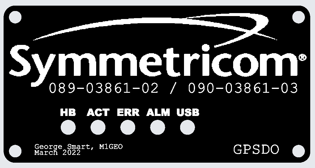
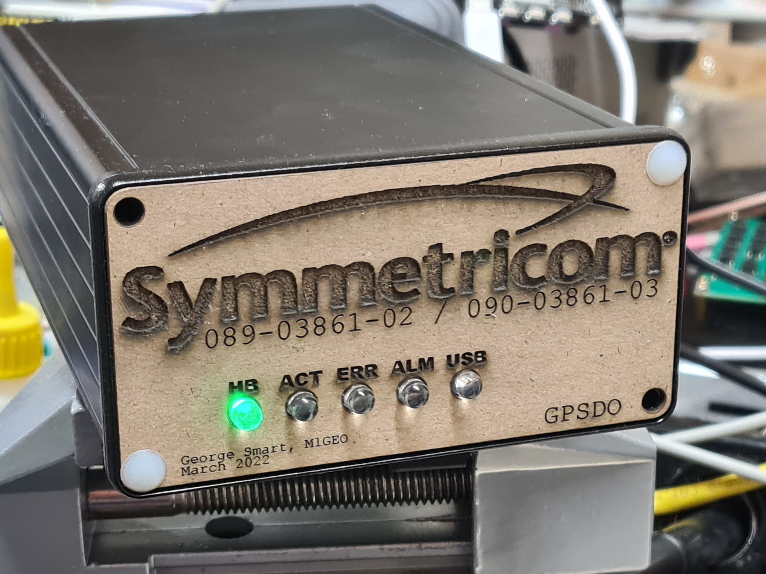
The carrier takes 5V at around 2A input on a 2.1mm x 5.5mm DC power socket, a USB-B connector and holds five LEDs: four main LEDs from the GPSDO (which are connected to test-points on the PCB, I can’t find the LED signals on any connector), plus one LED from the FTDI device showing USB activity.
The image below shows where the LED signals are taken from. For reference, the big IC in the centre is the Xilinx Spartan FPGA:
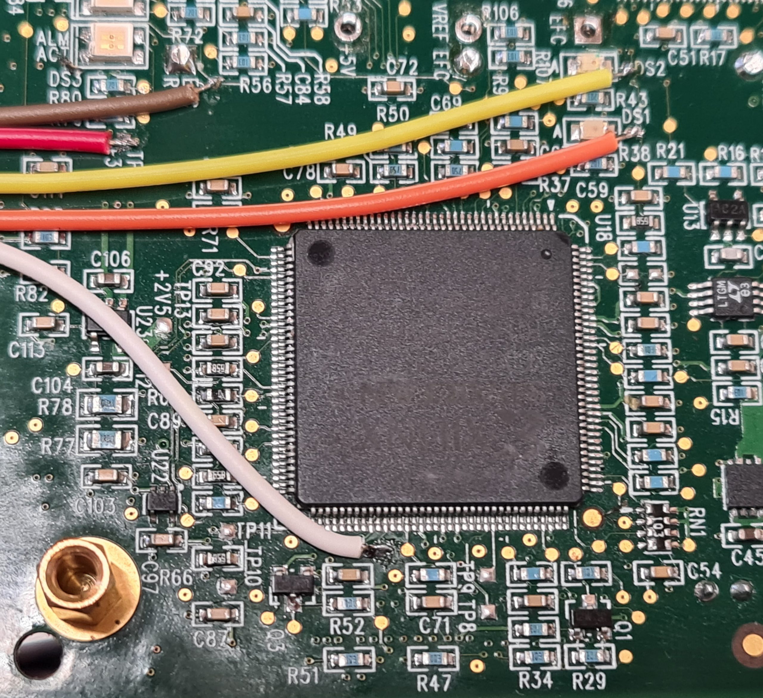
The LED signals are all common anode, fed from +3.3V taken from the board. The LEDs are fed through a resistor, and the individual cathodes connect back to either the CPU or FPGA through another of the wires:
- RED: +3.3V supply used to power the LED anodes
- BROWN: Alarm
- WHITE: Activity
- YELLOW: Heartbeat (DS2)
- ORANGE: Error (DS1)
There are two other LED signals (DS3 and DS4) which aren’t connected.
From here, I created a carrier board which had the correct mounting holes for the Symmetricom module, and offered front LEDs to show status, an easy 5V interface and a USB-UART interface to the module control port. The final board looks as below:

With the module fitted, the board looks more like the following. Note, this was an earlier version of the PCB:
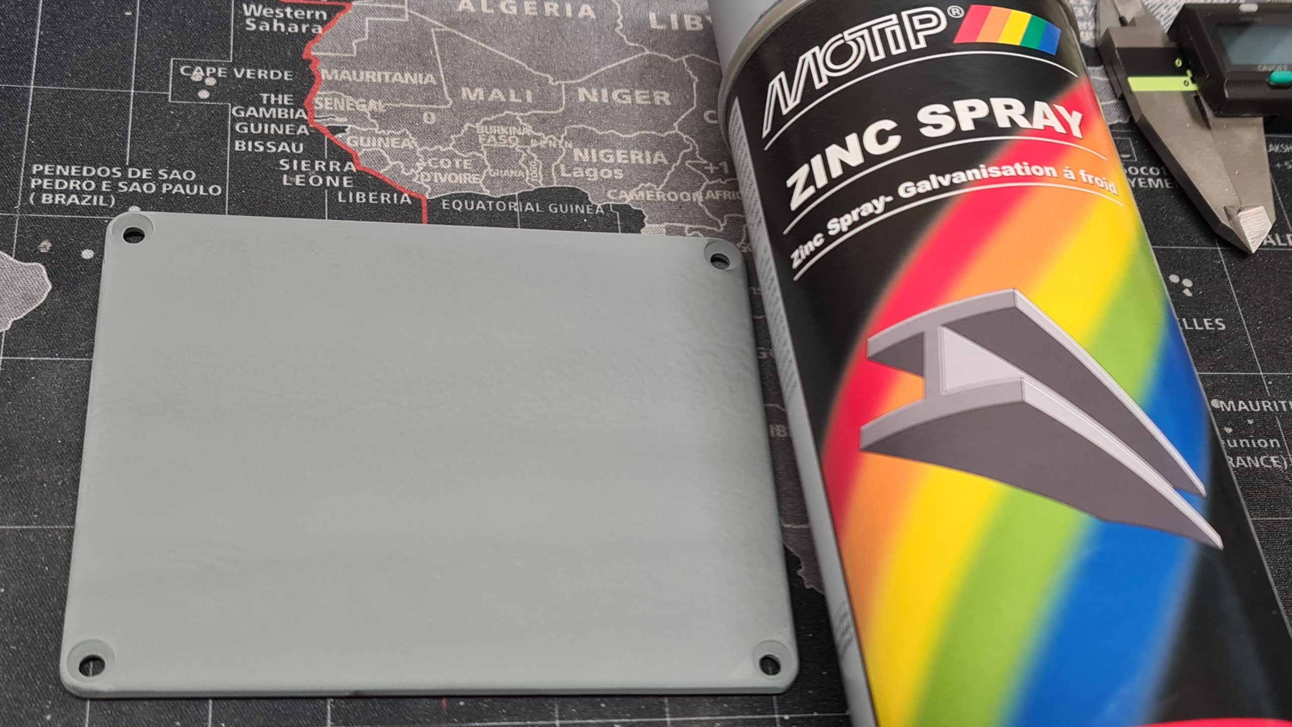
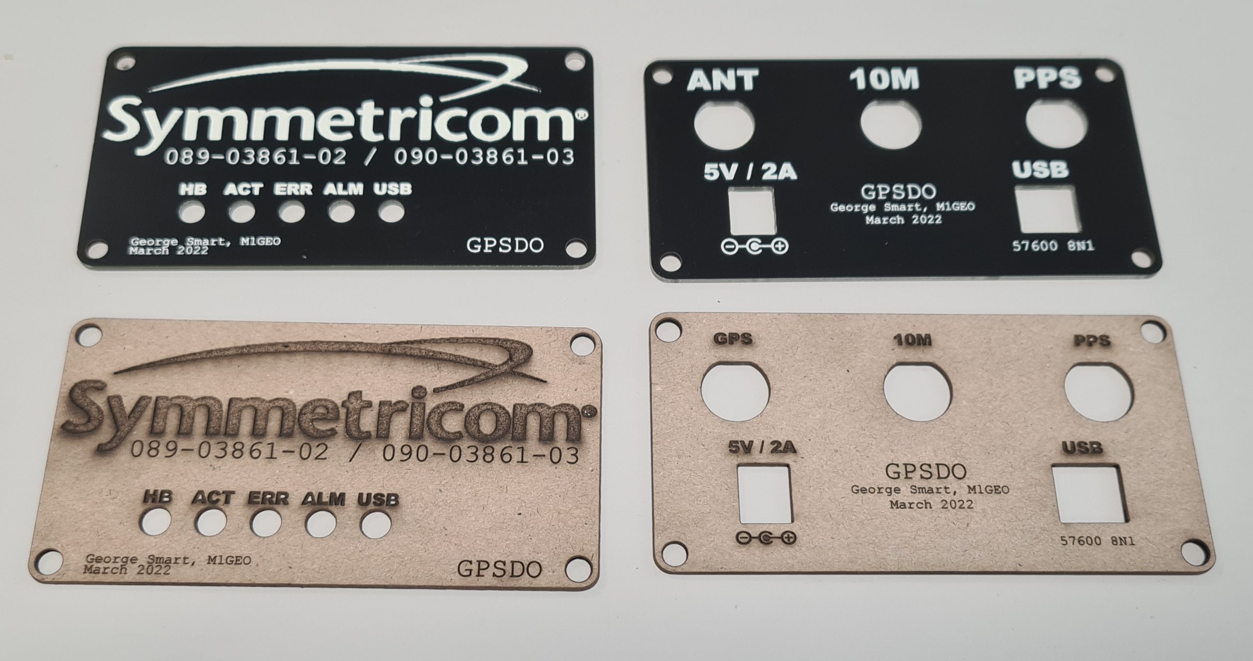
The project was designed to fit inside a Hammond Manufacturing 1455N1601BK case which takes a 160mm long by 100mm wide PCB, and the designed PCB fits the case nicely. By default, the Hammond case comes with either aluminum or plastic end plates, but I went to the effort to make PCB front and rear plates to enclose the case. Using PCB meant I was able to use tools I was familiar with to create the end places, and use the same order as the main carrier PCB. The copper on the PCB could be used to create a metal Faraday screen to enclose any electrical switching noise, and the silkscreen could be use to add legends, logos and decals.
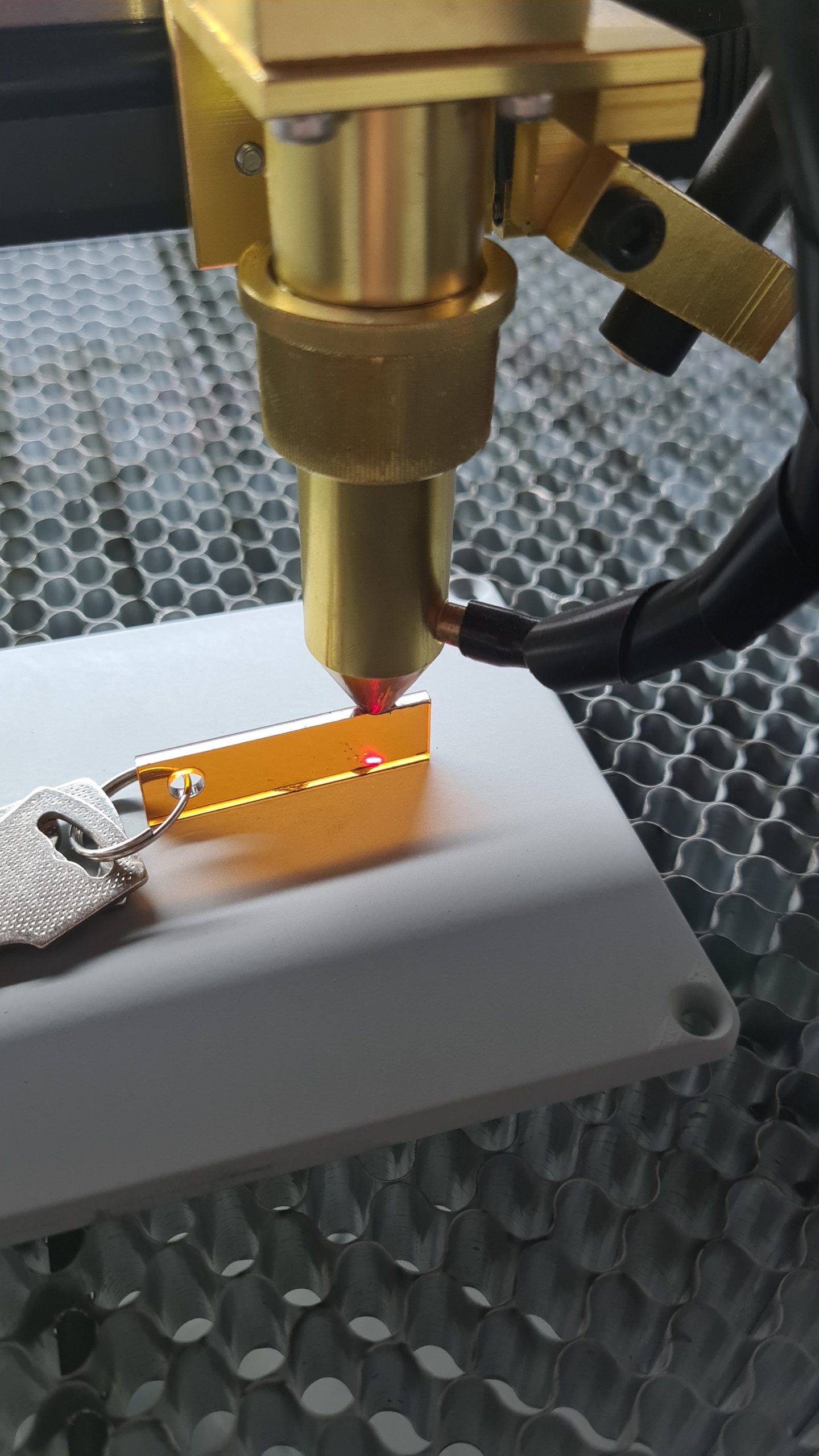
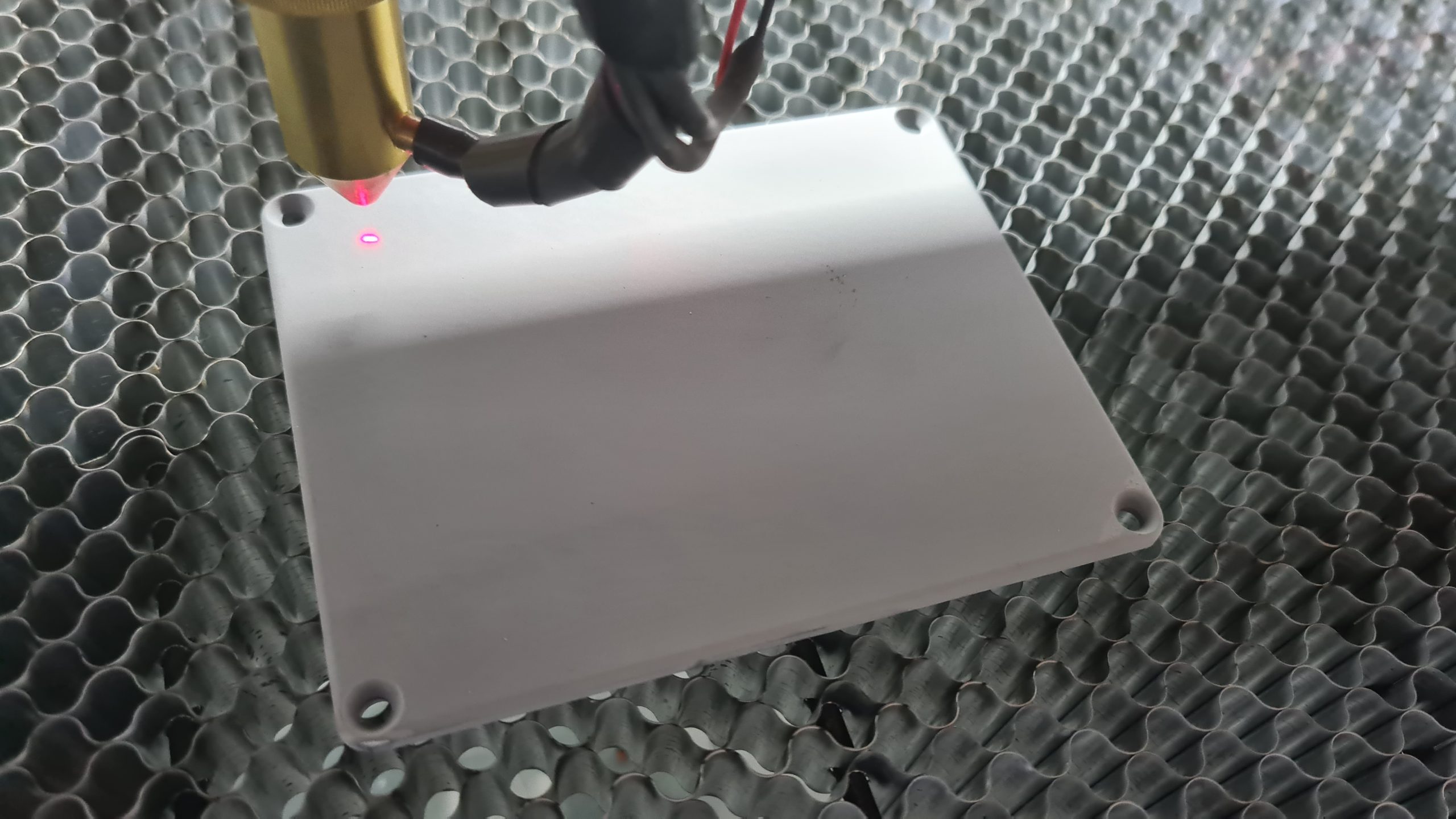
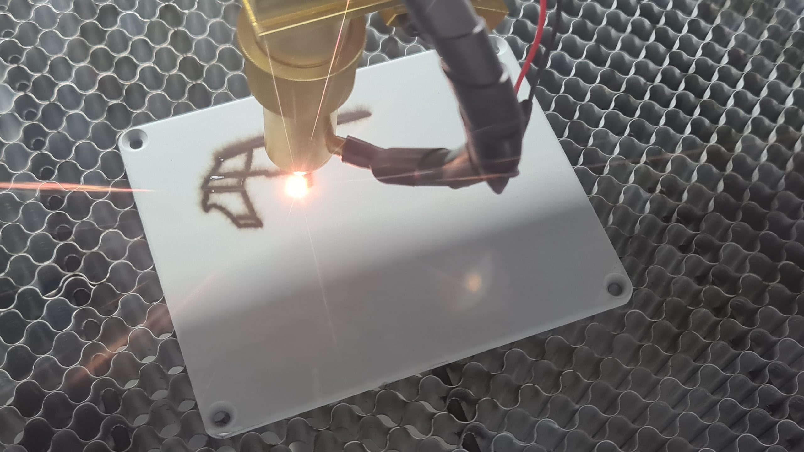
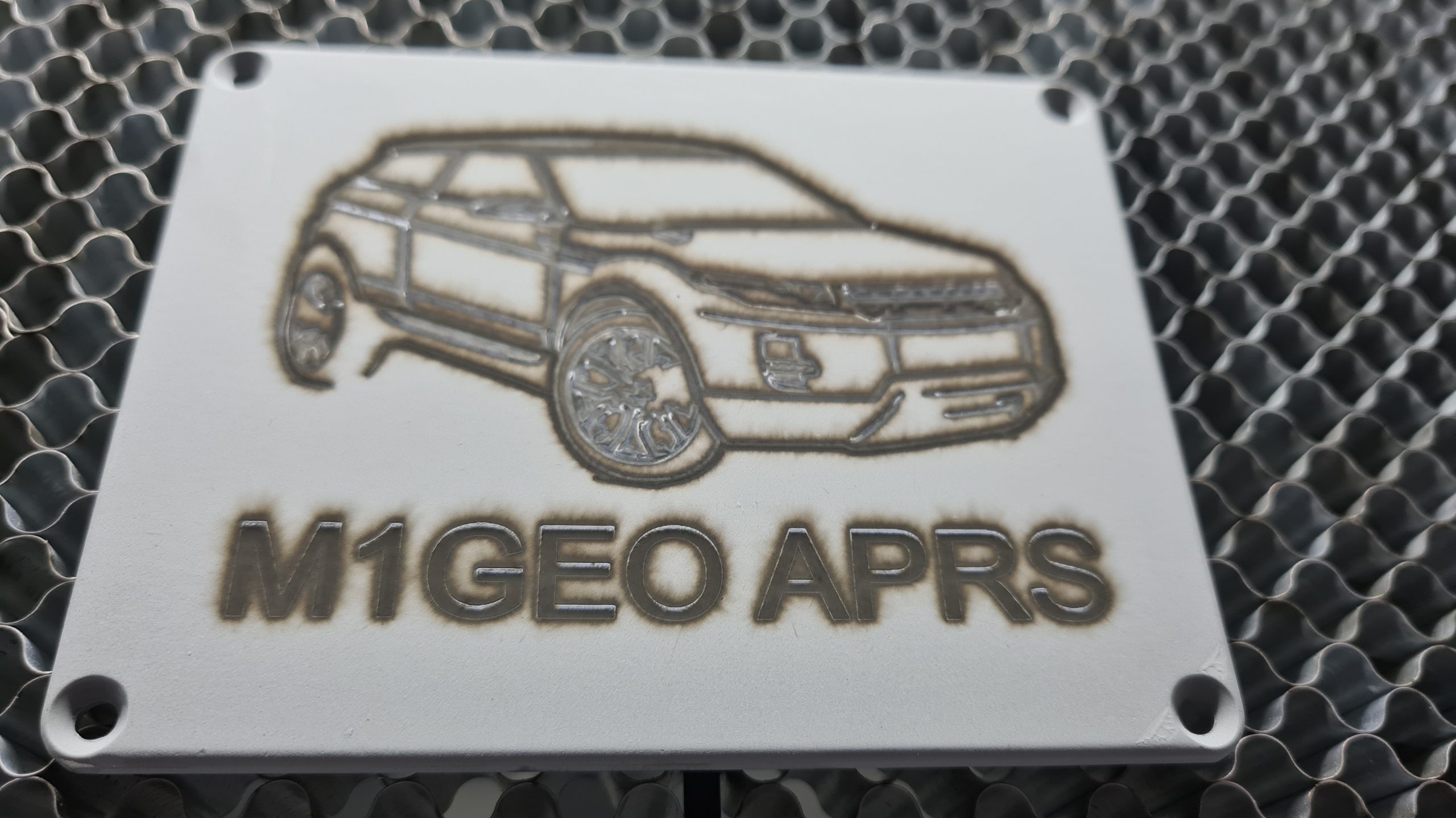
I prototyped the designs as below in the PCB package and then used my laser cutter to test them out for fit. A test fit of the front panel is shown below:
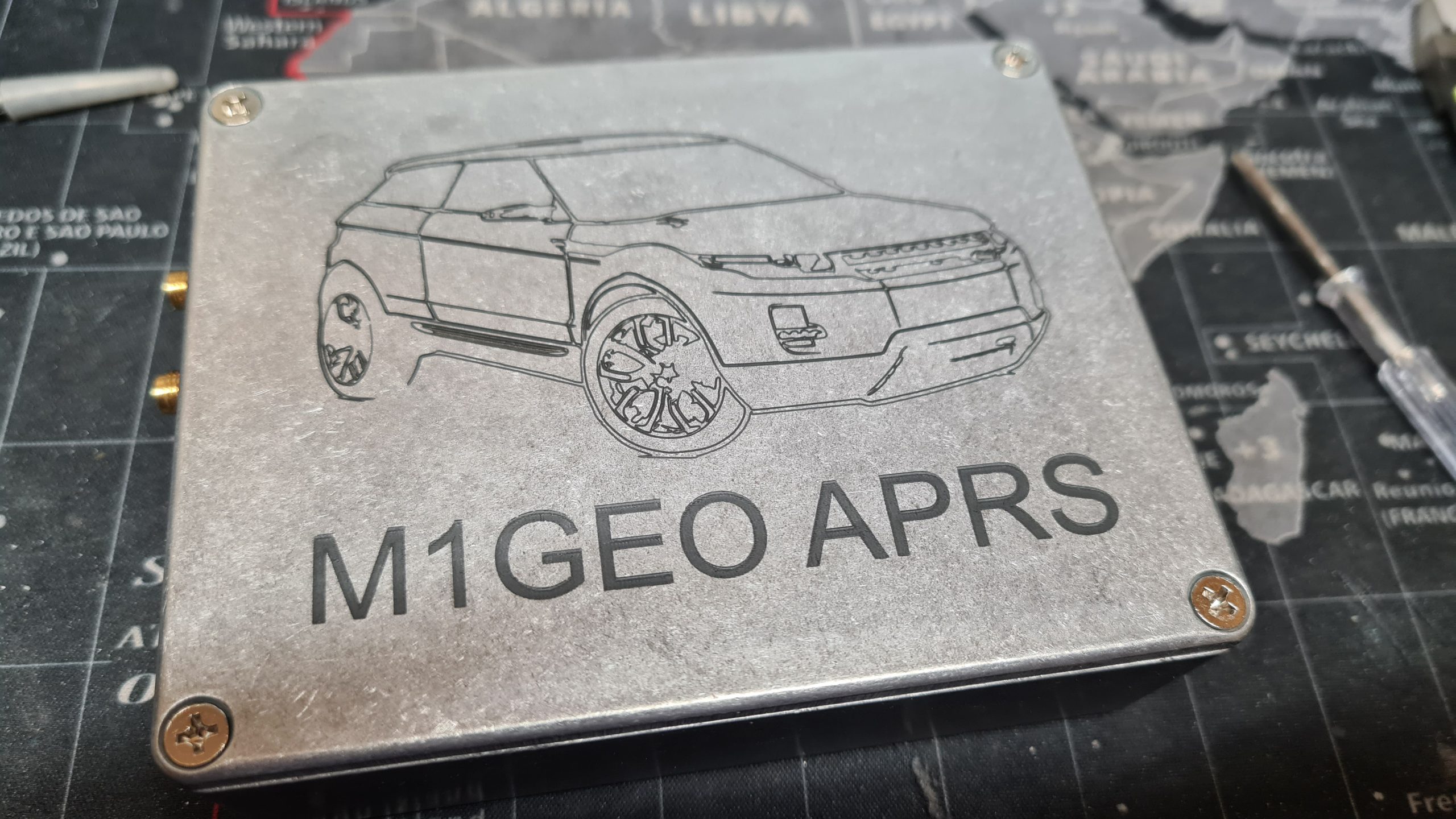
The below picture shows the PCB end boards as they arrived and the cardboard cutouts. There are some small tweaks, between the two, but overall the process worked well. One thing to note is that the internal cutouts for the BNC connectors are a little bit tight – in future I need to add an extra 0.5mm or so clearance (in addition to the 0.5mm clearance I left already). However, the connectors pushed in even if a little tightly.
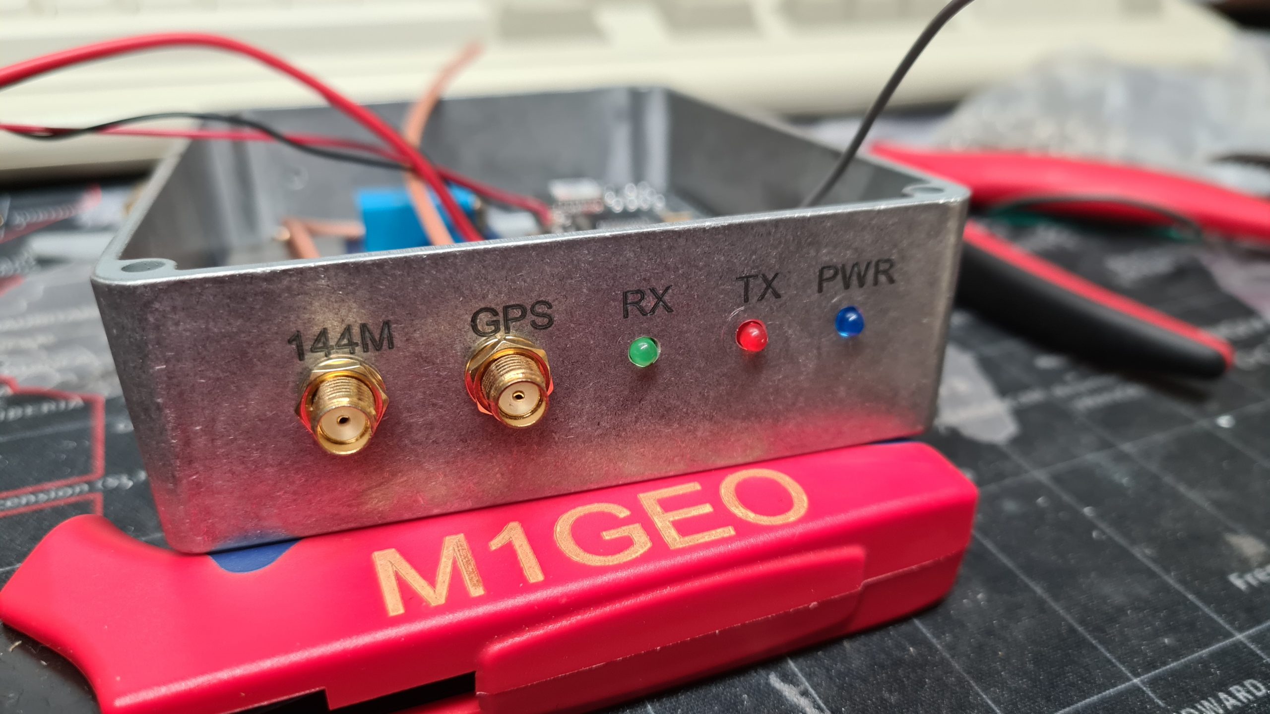
Final assembly went well, and I am very pleased with the results:
Build Notes
The following files are attached for version 1.00:
- Schematic
- Bill of Materials
- Gerber Files (contains front, back and inside PCB files)