
Final build information at the bottom. STL files here on Thingiverse 7392180.
Motivation
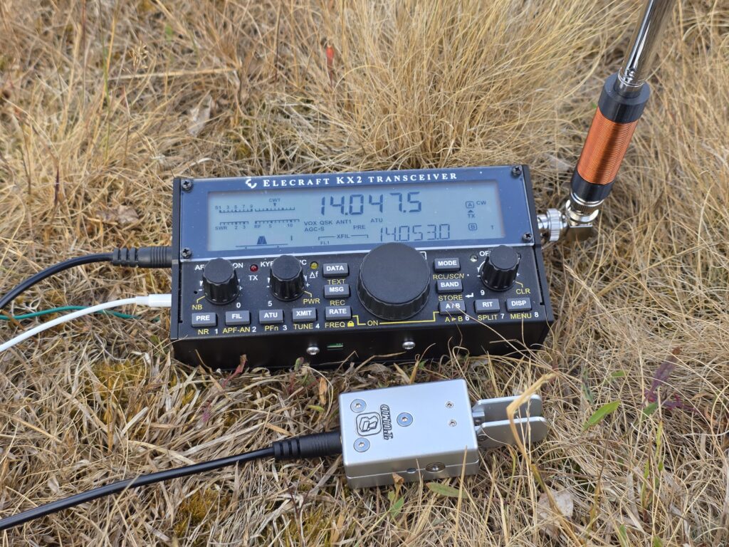
The idea of this antenna is to be a small, super convenient antenna for quick activations of parks and summits for POTA and SOTA with Ham Radio. A lot of the locations one may wish to activate are busy, and large HF dipoles are not practical. The aim of this antenna is to get on the air with no external antenna to not annoy other members of the public.
One similar such example of this is the Elecraft AX1 antenna, which covers a couple of bands with a switch: 14 MHz (20m), and 18 MHz (17m) + 21 MHz (15m).

The SOTAreflector is full of AX1 clones like these, but I have decided to add my own here. I wanted to make something elegant, simple and reliable. I wanted to have a way to do a bit of HF on summits that were busy, such as Yr Wyddfa (Snowdon) GW/NW-001. Below, you see how busy it can get – it’s only a matter of time before someone becomes tangled in my HF dipole!

The Beginnings
The basic theory of a loaded whip is to insert inductance in series with an antenna whip to make it electrically longer, despite it’s short physical length. For my use-case, the only practical solution (as with Elecraft’s AX1) is base loading. This is least efficient, but most practical.
I found the longest whip I could; this happened to be 1.2 metres long when extended, and 18cm when collapsed. The base is 10mm diameter and it has 10 telescopic sections.

I settled on making the antenna for 14MHz (20m) band, since it felt like the best compromise between being a busy band and highest frequency (least amount of inefficient loading).
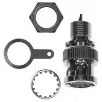
My planned to use the antenna with my Elecraft KX2 transceiver, using the internal ATU to match the antenna, again similar to the AX1. Therefore, a BNC connector would be needed. Conveniently the right compromise between size and strength, as well as matching the KX2. Since the KX2 has a female BNC, the antenna would need to be male.
For grounding, I decided to use the ground lug on the KX2 to avoid complicating the antenna design further.
With the key requirements all figured out, it was time to design the loading coil.
The Loading Coil
The loading coil’s job is quite simple; add inductance to the whip to make the antenna seem electrically longer. We’re trying to match the radio’s 50Ω output to the high impedance of the whip — and it will be high impedance since it is considerably shorter than the 1/4-wavelength.
Previously when making a 30m coil for the MA-12 antenna, I used a variable coil and adjusted it to correctly match. However, this was not practical this time around, so I decided to compute things mathematically. To do this, I used John M0UKD’s loaded whip calculator. John’s page goes into the mathematics of the calculation in detail, but for now we just take the result.
I entered a frequency of 14 MHz into the calculator, and a whip length of 1.2m. I set the feeder to loading coil distance to 0m. Finally I took the average diameter of the whip of 7mm. The calculator gave me an inductance of 9uH. Out of curiosity, I tried a frequency of 10.1 MHz, too, which with the other settings unchanged, I got around 18uH of inductance required.
I settled on 15uH with the hope that I could get both the 10.1 MHz (30m) and 14 MHz (20m) bands out of the same loading coil.
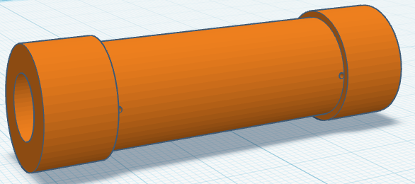
From here, I used John M0UKD’s air core inductor calculator to design a coil and assembly I could 3D print. The BNC would fit one end, and the whip the other end. The BNC connector I chose has outer thread diameter of 9.7mm; I printed the part’s connector side hole with 9.3mm so each side would have 0.2mm thread cut in each side. The plan is to screw the BNC in. The whip outer diameter had 10mm.
You can do as you chose to arrive at the required inductance (for me, 15uH), but I settled at a 15mm coil diameter, over 37mm coil length. I arrived at that length by balancing the number of turns required with the wire diameter (0.63mm outer diameter) to settle on 52 turns.
At this point, I knew I needed a 15mm coil diameter, 37mm long, to hold 52 turns of 0.63mm wire. I needed a hole of 9.3mm diameter at one end and 10mm on the other. I added a 1mm hole at each end of the coil. This was easily created in CAD, and before long I had V1 STL files ready to print.
Prototype V1
With the coil wound and V1 assembled, I had the bright idea to use an 18650 battery cell heat-shrink sleeve to hold things together. This worked well, but the BNC connector felt loose and fragile in the 3D print, so I tweaked the design further to get the BNC to screw into the plastic tightly and hold well. Full build instructions below.
The V1 in use looked something like the image below, with my KX2 mounted on its side; I plan to use a 90-degree BNC adapter in future, but keen to try it out I jury-rigged the below:
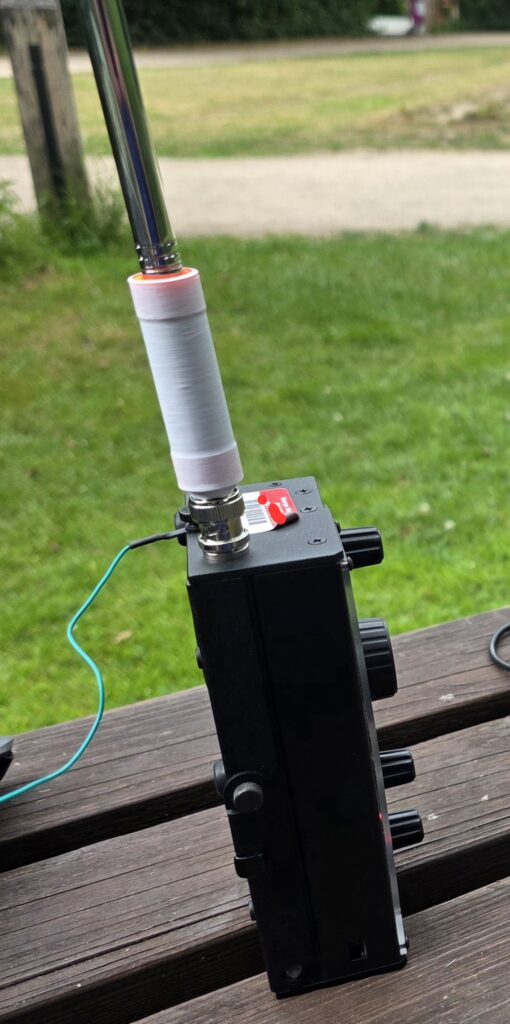
I used the antenna to activate a local park one evening, from POTA GB-5463 (Bramblefields Local Nature Reserve) working 11 contacts on 20m CW. Signal reports ranged from 599 to 319; clearly not the best antenna, but it did get the park activated.
The Final Version
For the final version (currently V5), I ended incorporating a few tweaks, along with printing the coil-former in black, purely for aesthetic reasons. I printed in PETG, but I don’t think that matters much.
To recreate this yourself, you will need:
- Male BNC panel mount, 3/8-32UNEF thread – I used Amphenol 112420
- 1.2m telescopic whip, 10mm largest section diameter
- 3D printed former (download from Thingiverse here)
- Enamelled copper wire, 0.63mm diameter, approx 2.8 metres
- Ground wire, approx 4 metres.
- Heat-shrink to cover – I used 18650 sleeve (optional)
Start with measuring out the enamelled copper wire. You need about 2.6 metres of wire for the actual coil and connections, but you’ll end up breaking the wire a few times trying to get the BNC threaded in, etc., so I’ve added a bit more to it.
Firstly thread the wire from outside of the BNC end into the connector and pull almost all of the wire through. Then feed the inside end back through the coil centre, out of the BNC end and solder it to the BNC connector centre. Leave most of the wire in a loose loop out of the other end – this will provide slack when the BNC is screwed in, hopefully preventing the wire from snapping from the twisting. Take care not to let the wire tie up; unwrap it every few turns so that the wire doesn’t bundle or knot.
Once you have the BNC connector tightly screwed into the plastic 3D print, carefully, without kinking the wire, pull the wire through the hole, close to the BNC so all of the wire is now outside of the coil, and only a short length goes to the BNC centre.
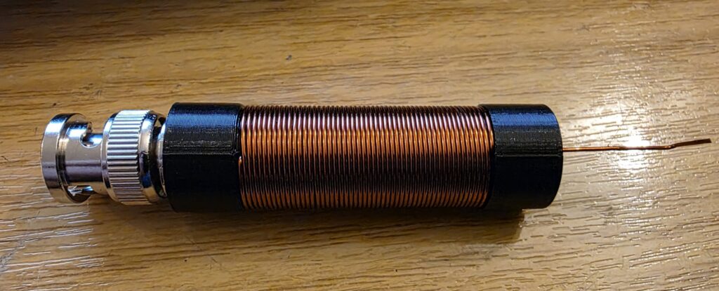
One you’re ready with this, wind the coil. You should take care to get the windings tight, otherwise they won’t all fit in. You need to wind 52 turns around the coil form. Once done, it should look like this…
Finally, connect the end of the wire from the coil to your telescopic whip. The whip I chose has a base part with an M4 screw protruding, so I attached to that inside with a small solder tag and nut & bolt, which gets hidden inside the coil assembly.
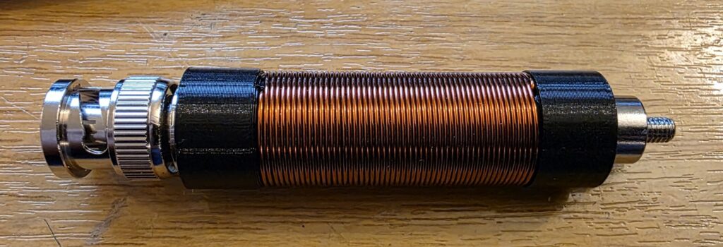
Now just the M4 screw and whip base is visible. The whip can be screwed onto the top of the antenna for use, or removed to pack inside a small travel case with the KX2.
I did a DC continuity test from the telescopic whip to the BNC centre to make sure it was connected, and a second test from the whip to the shield of the connector, expecting no connection – thankfully all was well!
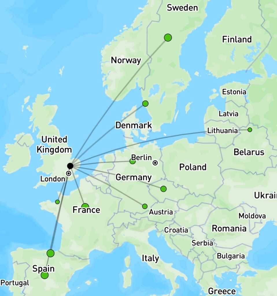
A quick test after building this final version revealed the following on the RBN on 20m at night.
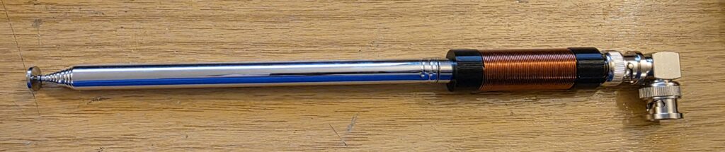
Once everything is working, you can add a tiny bit of super glue to any strategic points, and the finish off with a heat-shrink from an 18650 battery which are very cheap in plain colours and add protection. Conversely, you can get some cool printed designs on them for vape batteries which will add a bit of interest to the antenna!!!
Final Version Testing
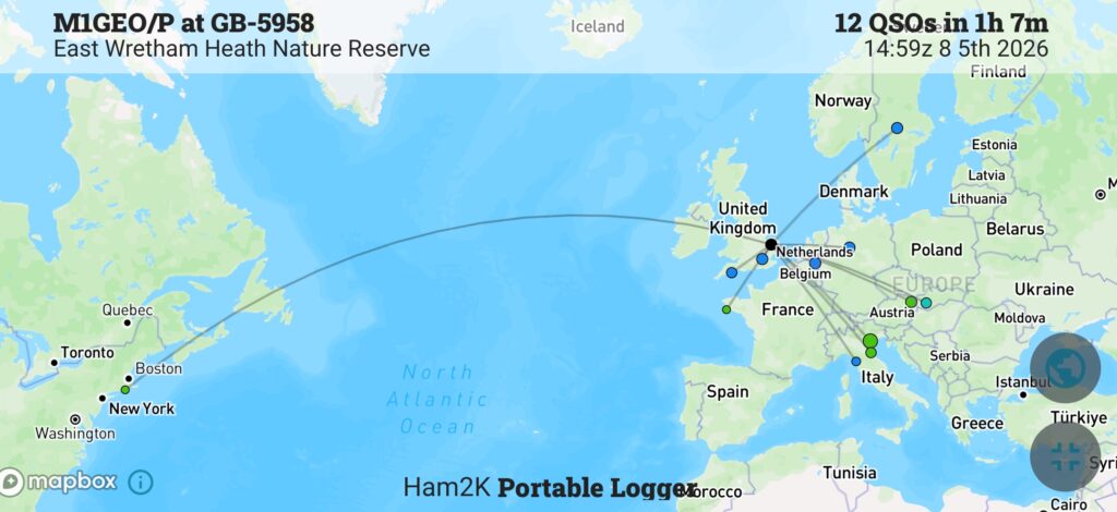
When it came to testing the final version, I took the “V5” out to POTA GB-5958 (East Wretham Heath Nature Reserve) on the 5th August 2026. The band conditions were poor on the higher bands, with plenty of QSB but my first contact was with KE1J in South Kingston, Rhode Island; around 3343 miles away. Not bad for 10W into such a compromise antenna!
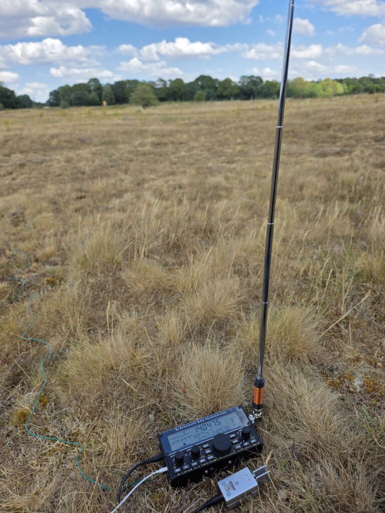
I went on to work 11 more stations, totalling 12 for the activation, and although signal reports weren’t amazing, the log was filling. The map below shows the contacts made on 20m and 30m CW.
The antenna delivered what I set out to achieve and I’m quite pleased with how well it turned out. It looks tidy and professional, and is very easy to deploy. Its light enough to be part of the standard kit, although I wouldn’t recommend on relying on it, it is a nice convenient backup for when you’ve exhausted VHF for contacts and you need just more QSO for your valid activation.