Category Archives: Computers

Marconi 2955 Firmware Upgrade

At Friedrichshafen Ham Radio flea-market 2022, I bought an old tired Marconi Instruments Radio Communications Test Set 2955 which I have spent a bit of time restoring. I now have it passing all of it self test, and the functionality seems good.

During the time I spent digging through the service manuals (link here) for the unit and my time exploring the Marconi Instruments GroupsIO, I noticed there was an updated firmware for the unit. Mine shipped with the very earliest V10 firmware. I saw ROM files in the forum Files section for V16. There are some upgrades from V10 to V16, though, rumour has it that anything above V13 isn’t much of an upgrade unless you’re using some of the cellular testing accessories. The V16 firmware files can be found here inside the Marconi Instruments GroupsIO Files section (along with many other useful things). Definitely a very useful group with knowledgeable people inside!

Below, we see the original version 10 firmware, dated 1986.

The EPROMs which need upgrading are IC9, IC10, IC11 & IC12 on the processor board. These are three of 27C128 128kbit (16kByte) EPROMs [IC9-IC11] and one of 27C64 64kbit (8kByte) EPROM [IC12]. I replaced all mine with the larger 128kbit 27C128 parts, copying the 27C64 binary image into both the lower (offset 0x0000) and upper (offset 0x2000) halves of the EPROM, so irrespective of the state of pin A13, the data output would be the same.

Rather than UV erase the original EPROMs in the machine, I purchased additional ones online (I got mine from AliExpress, but eBay, etc., all sell them). Mine ended up being brand new, never used, but previous ones I’ve bought were pulled from old equipment and needed erasing beforehand.

Using an EPROM programmer, I programmed the four 16kB ROMs onto the blank chips. This took around 10 seconds each using my TL866ii+ programmer.

To change the EPROMs in the Marconi 2955, you need to remove the top cover to be greeted with the insides of the 2955. The CPU board (AB4) we need is inside the locked metal cover. These are rotate-clips, not screws, so go easy on them!

Once you’re inside the metal screening box, you’ll see some boards stacked into the main motherboard along the bottom. We need CPU board AB4, which is the 3rd board up from the bottom of the picture (closest the screen). Use the ‘ears’ on the side to help lever the board from the motherboard socket below and slide the board out.

The CPU board AB4 is shown below. You can see the manufacturer stickers on 3 of the 4 larger EPROMs and the smaller flash EEPROM. From left to right, the 4 stickered devices are IC13, IC12, IC11, IC10 and the final, rightmost is IC9 with missing sticker (it had fallen off inside the machine).

IC13 is a flash chip (Xicor X2816AP) with your unit’s calibration data stored within – don’t overwrite this one any online! You can of course read/back up your calibration data if needed. I decided to copy my flash EEPROM IC13 into a new part, so that I could keep all of my older V10 PROMS together. I was worried that if something went wrong and the V16 firmware had ‘updated’ the formatting of the data in IC13, I may not be able to go back. I used a CSI CAT28C16AP that I had in the shack as I wasn’t originally intending to touch IC13. If you decide to replace IC13 also, I would suggest getting the exact part used in case it matters. These early flash chips are a bit fussy with timings, etc., and so interoperability isn’t guaranteed. That said, mine has been fine.

The 5 devices were replaced. I used a label printer to sticker each ROM as I wrote and verified its contents. The original chips were placed inside an antistatic IC tube, and wrapped in ESD-safe bubble-wrap , which I tucked inside the machine between the screened box and the power supply cabling on the motherboard. They sit nicely there, can’t move, and will be available should anyone wish to revert the machine.

After reassembling the unit, I fired the test-set up, and to my relief it booted straight up!

I was able to confirm the firmware upgrade had worked – below we see the software version is now version 16 (dated 1992).

Pressing the self-test button confirmed the basically functional. Excellent!

Erasing EPROMs in 2021

While chatting to a friend recently about an old Z80 CP/M machine I built based on Grant Searle’s Z80 CP/M machine, I decided to fire the machine up for a demonstration and give it a try.

No description available.

The machine had been in a shelf in my conservatory for well over a year since I last powered it, and when I connected the power, it was clear that there were signs of life, but, the machine was not happy at all! I could see bus conflicts on the data bus as well as very ‘broken’ behaviour.

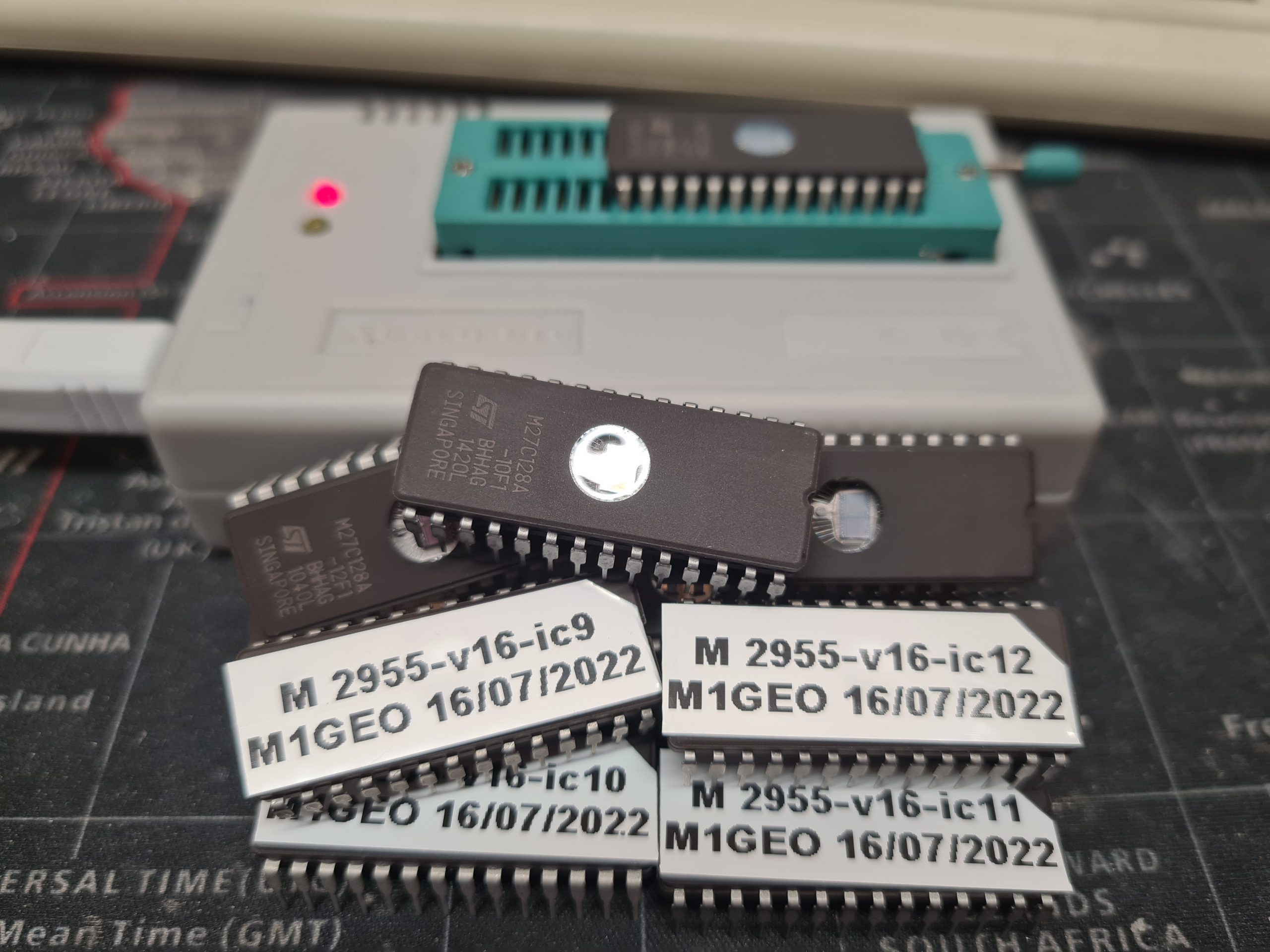
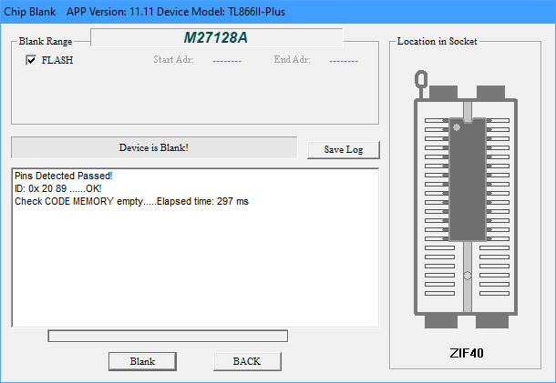
After probing around, I decided to check a couple of logic gate (those controlling the address and read/write lines) using my TL866ii+ programmer which conveniently supports logic gate testing and RAM testing. All of the logic gate ICs confirmed to be working correctly, as did the 128Kx8 RAM chip. Checking the EPROM yield a different story!

Forgetful EPROM

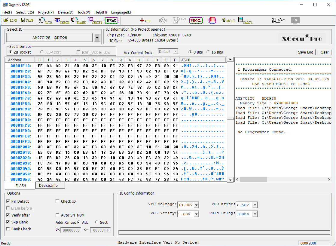
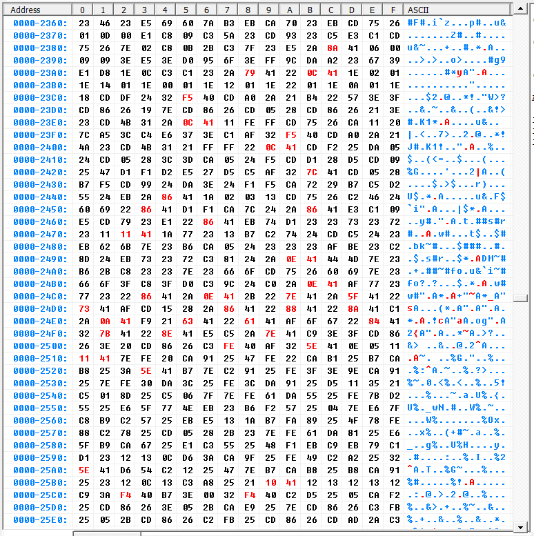
Some of the bits towards the end of the ERPOM had been erased (with UV erased parts, this means a ‘0’ bit had become a ‘1’ bit). The snapshot below shows in red bytes that had failed the verification.

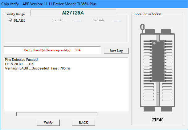
The first 0x2012 bytes were completely unaffected with 324 differences in total (just under 2% of the 0x3FFF bytes in the 16KB ROM) mainly concentrated in the end of the address range.

This teaches me to always cover the UV window with something opaque as per the datasheet’s advice. I know people say that sunlight can erase such devices, I never really believed them. As an aside, others have looked into this, which I had not seen until now: see this hack-a-day article for a timelapse of EPROM data when exposed to sunlight.

And, secondly, it left me in a quandary as to how I should restore the ROM code.

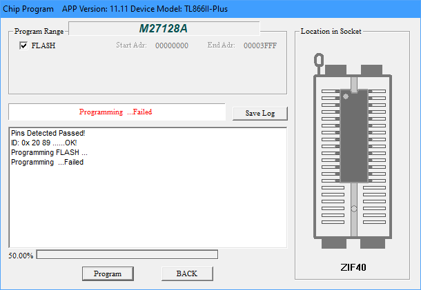
Initially I thought I should just be able to reprogram the device over the top of the existing code, since the changed bits would be reprogrammed back to ‘0”s from their current ‘1’ state. But, this turned out not to work. I’m not sure why, but the programmer would fail at 50% – just about the time the corrupt bits arrived.

I decided the next thing to do was to try and erase the IC – but how!?

Erasing UV EPROMs

I didn’t have one of the classic EPROM eraser boxes with a timer and a nice antistatic mat. I’d have to improvise. Essentially tinker around until the PROM was erased (reading 0xFF in all locations).

Eprom Eraser UV141 Professional made by Industrial electronics Ltd. UK

My first attempt was with a DSLR camera flash. I had seen these cheap EPROM erasers online that look like a xenon flash tube, so figured it was worth a shot. However it made no difference at all – I assume the camera flash has an UV filter.

My second attempt was with a UV LED, inspired Charles Ouweland‘s investigations along similar lines. Charles reports that this took 48 hours to erase the PROM. Like always, I was in a rush, so this didn’t really work for me. I could have driven a roundtrip to my parents (Dad has a proper UV eraser) in less then 4 hours including a cup of tea and a chat with Mum!

The third attempt was to use a UV insect-o-cutor which features UV fluorescent tubes as in the UV141 eraser pictured above. I placed the chip on the desk mat and put the UV insect-o-cutor directly on top such that the finger guard was on the top of the IC and the bars were not obscuring the window.

The scary part of this was that the high voltage aspect of the bug-zapper was popping on occasion with small insects – thankfully, the insects popping did not obscure the IC window nor cause ESD damage! After 20 minutes (the usual time I run the UV141 for) the IC was exactly the same. No additional bits had be cleared to logic ‘1’s. I suspect the output is UV-A and not the required UV-C.

Making a UV-C EPROM Eraser

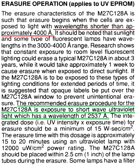
I went back to the second approach with the LED, this time consulting the EPROM datasheet (extract below), and noted that the recommended wavelength for erasure is 2537Å (253.7nm). This puts the UV light required to erase the EPROM in the UV-C spectrum.

I set about trying to find an LED with the correct wavelength. Some more digging showed up the VLMU35CB20-275-120 UV-C (270-280nm peak) LED offering a typical 13.5mW. Such wavelengths are common for curing acrylic nails and for sterilising surfaces in medical applications. At the time of writing, one such LED costs around £4.50 with VAT.

Constant LED Current

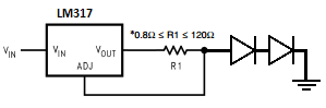
These LEDs appear to require between 5.0 and 7.5V at 120mA. I opted to create a simple constant current device using an LM317 set to 120mA and the two LEDs in series. This should work fine when supplied with at least 18V (7.5V + 7.5V + 3V [LM317 dropout voltage]). A SOIC8 LM317 is capable of 200mA and low profile enough to allow the LEDs to be close to the EPROM without catching. R1 is chosen to cause a voltage drop of 1.25V (the LM317 reference voltage) at the desired current. See this TI flashback for more details.

R1 = 1.25V/I = 1.25/120mA = 1.25/120e-3 = 10.4Ω. The closest easily available value is 10Ω, which checking backwards would give a current of 125mA. Since the datasheet mentions 150mA supply giving increased power, I have chosen to go with 10Ω as this will not damage the LED.

We should also consider the size of R1. The power dissipated in the resistor is easily calculated:

P = I^2 x R = (125mA)^2 x 10Ω = 120e-3^2 x 10 = 0.144W = 144mW.

So, a standard ¼-Watt through-hole resistor would be fine. For surface mount, 0805 resistors are typically 100mW, so a combination of multiple resistors should be used to handle the power. This could be four 10Ω parts in series-parallel, two 22Ω resistors in parallel (making 11Ω [114mA in the LEDs]), or two 4.7Ω resistors in parallel (making 9.4Ω [133mA in the LEDs]). I’ll opt for two 4.7Ω resistors since this is still below the maximum recommended working current of 150mA.

Designing the PCB

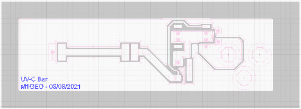
Initially I had considered tacking two wires on the LED and using a lab power supply to power the LEDs. However, I figured if I was making a constant current supply – mainly to avoid a “oops!” moment and pop £8 worth of LEDs – I would make a PCB to house it all. This way, I could keep the board with the EPROM programmer in the programmer box. The design brief would be simple. The PCB should fit inside the EPROM programmer (TL866ii+) box. The PCB should be (maximally) 110x50mm. I figured 100x50mm would be a nice size. A 5.5×2.1mm DC jack would allow for easy connection to wall-wart PSU or other power source. The rest was just two LEDs, and LM317, two resistors and a decoupling capacitor or two!

Since the PCB is quite simple, I figured it would be a good candidate to make with a laser cutter. Above shows an overlay of the Gerber edges and the layer to be etched. The back areas are there copper is to be removed. The white areas will remain copper.

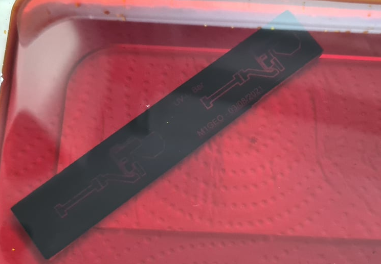
The board was created by coating a standard single-sided FR1 copper PCB blank with black paint from an aerosol can. This will be used as the etchant mask. The laser cutter is then able to remove the mask by burning away the paint layer, exposing the copper to the etchant.

No description available.

Typically, I’d also cut a solder mask from mica sheet to help apply paste, but for such a simple board, it isn’t worth the extra effort and waste materials.

The next job is to etch the PCB in ferric chloride – you should strive to make a much better job than I did!

I completely over-etched by board by having the etchant too cold and leaving it far too long! But hey, it’s been 10 years since I last made a PCB in my (parents) kitchen sink!

No description available.

From the image above you can see that my 10 thou track has completely disappeared in the right etch, and has almost completely disappeared in the left. I then proceeded to make a mess of drilling the connector holes, misreading a 4mm drill as a 2 mm. The board ended up as a total mess, but, I got it working!

No description available.

My apologies for making such a mess of the board. However, as you can see, the two LEDs are lit and a current of 117.3 mA flows through the series LEDs. I may tweak the resistor values to get an extra 10mA or so, but for now, the result is good enough!

So, now to erase the EPROM

With the PCB made up, I eagerly put the EPROM back into the reader and loaded the old ROM code in. I reverified it to see that indeed 324 mismatches showed up, just as before. Confirmation that all my previous attempts had failed!

I held the newly made PCB above the UV window and gave the EPROM a 1 minute ‘blast’. I read the EPROM again, curious to see how many extra bytes failed verification. Too my surprise, 1088 byte failed verification – considerably more than before. I looked through the data and could see a pattern; the EPROM was blank. Sure enough, the 1 minute blast was enough to clear the EPROM!

I guess it just goes to show what having the right tools for the job can do!

Now will the computer boot?

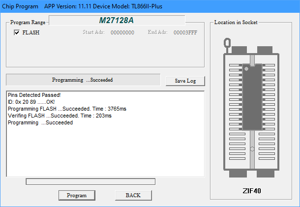
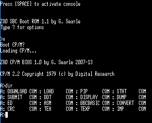
Since I was on a roll, I reprogrammed the EPROM with the Z80 CP/M code and went for a test boot.

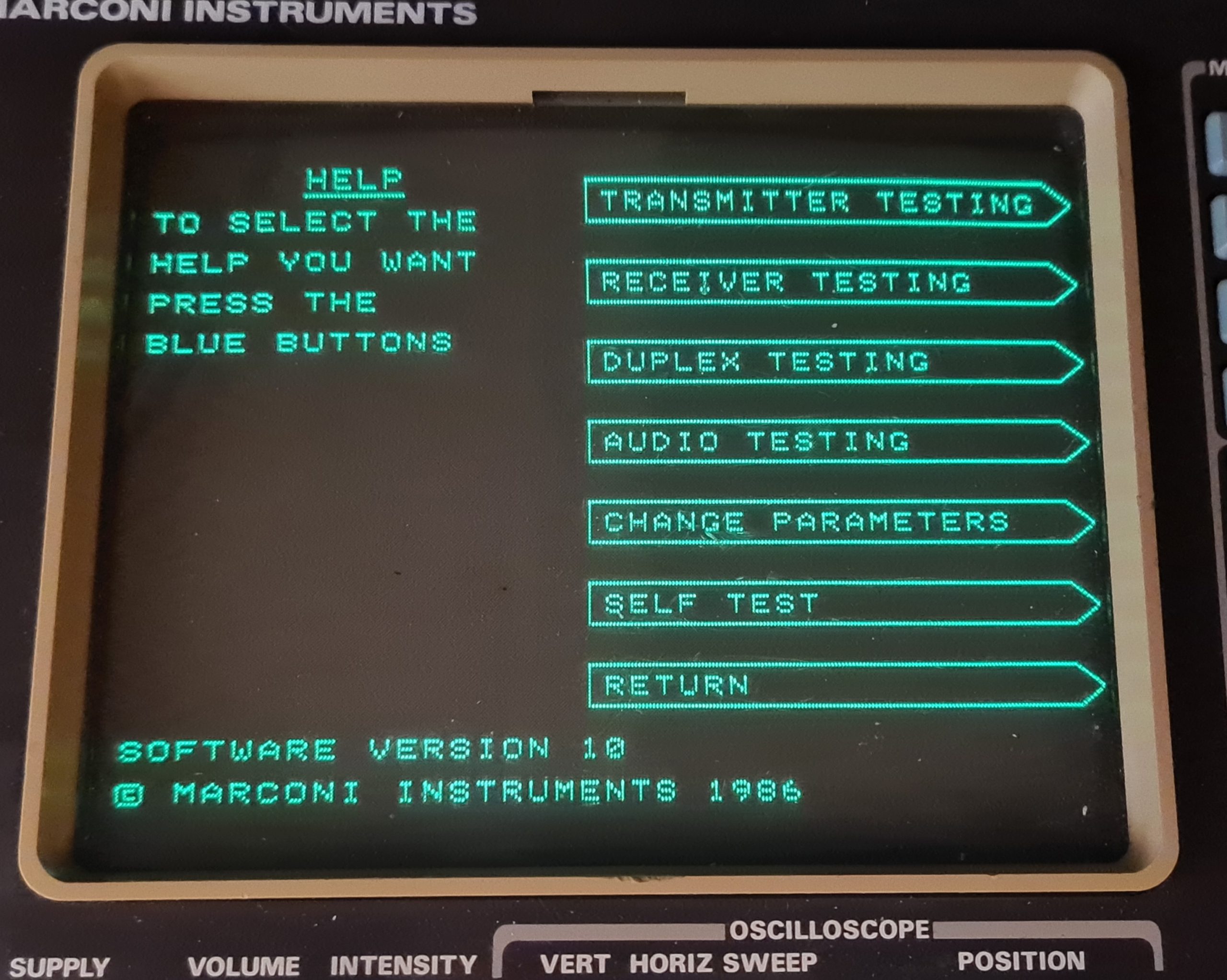
And we’re back to life! This is a machine based on Grant Searle’s Z80 CP/M machine.

Folding AT Home with CPU and Nvidia GPU on Ubuntu

With the outbreak of the novel coronavirus (COVID-19) in late 2019 and spreading through Europe early 2020, a lot of tech and IT media wrote to encouraging people to take up Folding at Home (FAH, F@H). I decided to join in, which for the most part was pretty easy, just a case of installing the software – more on this later. But on my larger PCs, I wanted to make use of my Nvidia GeForce GTX 1070. Using a GPU adds another workhorse to the project, and is often faster/more suited to some of the computation tasks (called Work Units or WU).

Installing the Software

The Folding at Home software comes in 3 parts: the client (FAHClient) which does the computation work; the controller (FAHControl) which provides a GUI for the client; and a viewer (FAHViewer) which renders pictures and illustrations of the molecules being computed, albeit at the expense of some compute performance.

The FAH Downloads Page has the files you need to get started. On Linux, you’ll need the following files:

These should be installed with the following command:

$ sudo dpkg -i <package_deb_file>
$ sudo apt --fix-missing install

The first line installs the package and the second will obtain any dependencies for the package. You may see errors after installing the first package, but after the second, you should have any dependencies met. You may need to tinker around and help the package manager fix any missing issues.

You’ll notice that I have supplied a modified version of FAHControl. This has one of the dependencies removed, which means it is possible to install on newer Ubuntu versions.

Once you have the programs installed, the client will start. You can stop and start it with:

$ sudo service FAHClient stop # stop the client
$ sudo service FAHClient start # start the client

You’re ready to go. Use the control program to make changes to settings, etc. You’re ready to start folding on your CPU!

You may be interested to benchmark your machine with FAHBench. The process takes a little over a minute to run a 1 minute test, and it reports if everything is working correctly. Fror

Setting up the Nvidia GPU

The more tricky part, for me at least, was getting the environment set up for the Nvidia display.

The first thing to do is to open the “Additional Drivers” dialogue box from the “Software and Updates” menu. You can jump directly to this by running the following in a terminal:

$ software-properties-gtk --open-tab=4

Typically, you should select the newest driver available. At the time of writing, “nvidia-driver-435”. If you are not running an X server and just want to install the driver without the requirement for X, you can install “nvidia-headless-435”. You may also care to install “nvidia-utils-435”.

After pressing Apply Changes, the system will download the latest drivers and install them with the required dependencies. We’ll add some extra packages of our own too:

  • nvidia-opencl-dev
  • ocl-icd-opencl-dev

Install the above libraries using the following:

$ sudo apt install nvidia-opencl-dev ocl-icd-opencl-dev

At this point, you should be ready to go…

Advanced GPU Tinkering

You may also wish to tinker with the GPU a little bit, choosing to either underclock or overclock the GPU to get either better reliability or improved performance. One thing to note with overclocking is that while the occasional glitch or artefact is acceptable during gameplay, it will cause a FAH WU to fail.

Initially with my configuration, I fount the factory overclock on my Asus ROG Strix GTX1070 O8G to be slightly unstable in FAHBench. I found that the GPU would fail at at between 7% and 9% of the way through the test.

Further investigation using the Unigine Superposition as a GPU stress test allowed me to tinker with the settings to find a reasonable GPU Core and Memory overclock parameters, as well as appropriate power limits. The Asus ROG Strix GTX1070 has good cooling and so I was able to get away with increasing the power limit and adjusting the clocks for long-term stability. Bear in mind that stability is way more important than getting that last couple of percent from the card.

Overclocking and tinkering was done using a mix of Green With Envy and the “nvidia-settings” tool on Xubuntu 19.10 which come with the driver and “nvidia-smi” which comes with the “nividia-utils-xxx” package.

Other Considerations

If you don’t fancy pushing your expensive graphics card hard, you may be able to find a custom GPU card previously used for mining crypto-currencies. These cards feature the same GPU chipsets, but are crippled such that they cannot easily (although it is possible) generate video. The Nvidia P106 offers features similar to the GTX 1060, while the Nvidia P104 offers features similar to the GTX 1070.

Since GPUs are no longer viable to generate crypto-currency, they’re often sold second hand on eBay and similar sites for relatively cheap prices. While a modest Nvidia GTX 1060 with 3GB of VRAM costs around £150 on eBay at the time of writing, an Nvidia P106-90 (GTX 1060 with 3GB VRAM) costs as little as £26 each or £20 in bulk! At a once off, that’s nearly a sixth the price.

Watch this space for an update on how these perform…