
I recently purchased a Fogstar Drift PRO battery to use in my motorhome for leisure power. The battery has RS485 and CAN connectors on the top. This page documents what combination of things worked for each interface.
At the moment, this is just a dumping ground of what works and what doesn’t. The plan is to update this information as I get more working.
It appears the BMS version is ‘JBD-SP04S060-300A-L4S’.
CAN bus
Controller Area Network, or CAN, bus interface is a robust vehicle bus standard that enables communication between electronic control units (ECUs). It has grown widely and is commonly used in industrial control.
RJ45 connection: CAN socket on battery
Pair:
- CAN-H: Brown/White (RJ45 pin 7)
- CAN-L: Brown (RJ45 pin 8)
Speed: 500k
If the BMS is asleep, you must send data to field ID 0x35E to wake the BMS and to let it know there is a controller present. Documentation I found suggested sending 8 bytes of 0xFF to the field, but it didn’t seem to mind what the data was. Once awake the BMS will stream for about 20 seconds before sleeping again. Guidance seems to be to periodically send something to field ID 0x35E to keep the BMS awake.
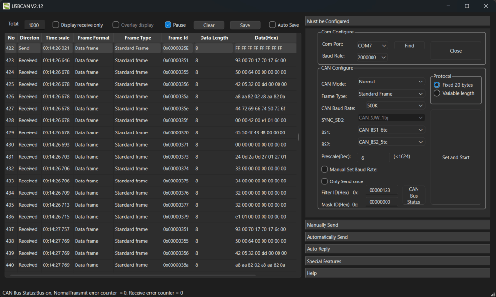
I tried to parse the data from the CAN interface using the Victron protocols. The data isn’t fully VE.Can compliant, but sends “Victron compatible” data, including fields such as 0x351 (battery status), 0x355 (voltage limits), 0x356 (temperature & capacity), 0x35A (cell voltages), and the aforementioned 0x35E (kick message, sent to BMS from host).
The protocol seems to be a broadcast only protocol (after the kick message to wake the BMS) following a JBD telemetry scheme.
I did play around with the data, but got less useful results than with RS485, so I stopped and moved on. Here’s as far as I got; you can see that there is some nonsense…
| Field ID | Raw Data (8-bytes) | Notes |
| 0x00000351 (battery status) | 93 00 70 17 70 17 6c 00 | 93 = charging permitted, discharging blocked. 00 = no errors 70 17 = 0x1770 = 600A max charge 70 17 = 0x1770 = 600A max discharge 6C = 108% state of charge (!?) |
| 0x00000355 (voltage limits) | 50 00 64 00 00 00 00 00 | 00 50 = 0x0050 = 8V max charge voltage (!?) 64 00 = 0x0064 = 10.0V min discharge voltage |
| 0x00000356 () | 42 05 32 00 dd 00 00 00 | Temperatures? |
| 0x0000035a | a8 aa 82 02 a8 aa 82 0a | Cell voltages, 24-bit? |
| 0x0000035e | 44 72 69 66 74 50 72 6f | ASCII: “DriftPro” |
| 0x0000035f | 00 00 42 00 e1 01 00 00 | Status/capacity? E1 01 = 0x01E1 = 481 Ah, battery capacity |
| 0x00000370 | 45 50 4f 43 48 00 00 00 | ASCII: “EPOCH” |
RS485 & ModBus
RS485, also known as TIA-485 or EIA-485, is a standard defining the electrical characteristics for serial communication. It’s commonly used in industrial settings due to its ability to transmit data over long distances and in electrically noisy environments.
The first option to explore is to use ModBus over RS485 to see what we can find. ModBus is a client/server data communications protocol in the application layer, originally designed for use with programmable logic controllers (PLCs). It has become a de-facto standard communication protocol for communication between industrial electronic devices in a wide range of buses and networks. For this reason, it’s a good bet to start with on our BMS.
RJ45 connection: RS485 socket on battery
Pairs:
- A+: Brown/White (RJ45 pin 7)
- A-: Brown (RJ45 pin 8)
Speed: 9600
Protocol: ModBus
Slave ID: 1
Can read registers and the data seems accurate. Used a simple MAX485 part coupled to a UART with a test Python script that scanned baudrates, and slave IDs trying to read registers.
The image below shows QModMaster scanning Modbus registers using function code 0x03 (read holding registers):
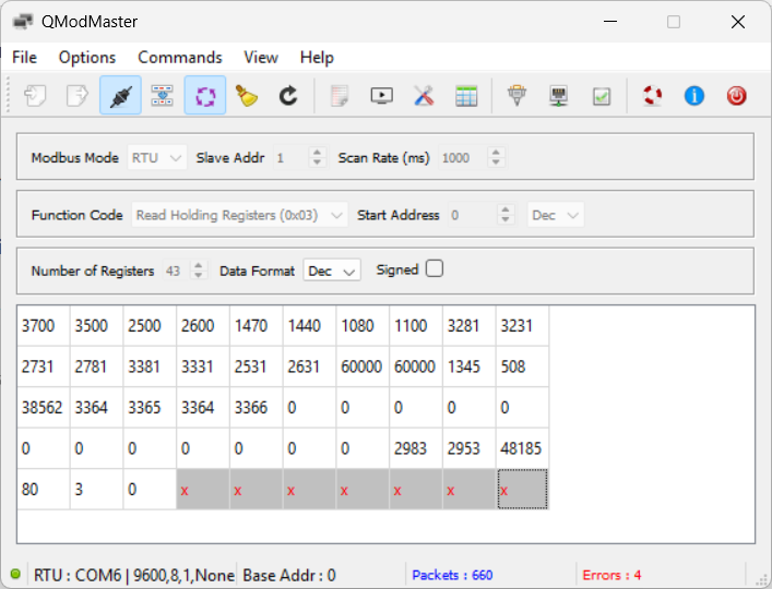
Guessing at some register values:
| Register Address | Raw Data | Notes |
| 0 | 3700 | Cell OVP, 3700mV |
| 1 | 3500 | Cell OVP release, 3500mV |
| 2 | 2500 | Cell UVP, 2500mV |
| 3 | 2600 | Cell UVP release, 2600mV |
| 4 | 1470 | Pack OVP, 14.7V |
| 5 | 1440 | Pack OVP release, 14.4V |
| 6 | 1080 | Pack UVP, 10.8V |
| 7 | 1100 | Pack UVP release, 11.0V |
| 16 | 60000 | Maximum charge/discharge current, 600.00A |
| 17 | 60000 | Maximum charge/discharge current, 600.00A |
| 18 | 1345 | Battery voltage, 13.45V |
| 19 | 508 | Battery current, charging 5.0A |
| 20 | 38562 | Current battery capacity, 385.62Ah |
| 21-24 | 3364-3366 | Individual cell voltages, ~3.365V |
| 25-37 | 0 | Unsure? Always 0 |
| 39 | 48185 | Maximum battery capacity, 481.85Ah |
| 40 | 80 | Battery state of charge, 80% |
| 41 | 3 | FETs status: bit-0: Charge FET (on) bit-1: Discharge FET (on) |
| 42 | 0 | Changes with reg-41 (went to 4096 when discharge was disabled) |
| ?? | ?? | NTC1, 25.1C |
| ?? | ?? | NTC2, 22.1C |
| ?? | ?? | NTC3, 22.1C |
| ?? | ?? | Cycle Count, 13 |
RS485 & JBD Proprietary Protocol
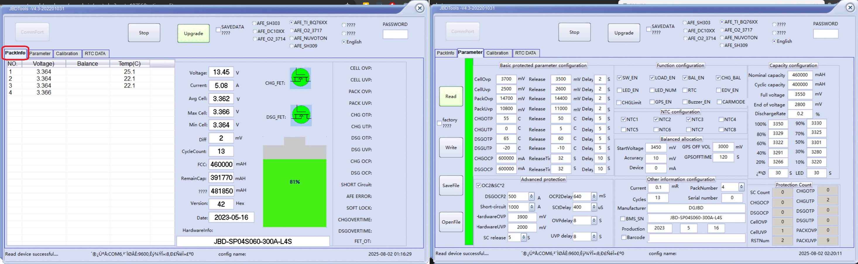
The JBD BMS application seems to parse some data from the JBD-SP04S060-300A-L4S BMS, as can be seen below. Note that not all data is parsed correctly, as the Drift Pro likely has custom firmware.
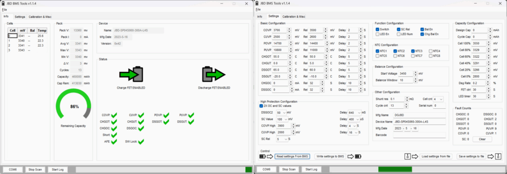
The opensource bms-tools project also parses the data from the JBD-SP04S060-300A-L4S BMS, and looks remarkably similar to the JBD tool, though it is written in Python. This makes it a great resource for copying sections of code!
My end goal is to make a display for use in my campervan showing the key metrics from the battery. Using ModBus, I couldn’t find registers containing the number of cycles or the temperatures. I would like to have these displayed.
It is clear the values I want are present in the datastream, all that remains is to parse the JBD protocol to get it.