
I have been interested in APRS for years, and have been running a homebrew APRS Tracker in the car for a good few years too, as well as MB7UCL and various other bits and pieces on the APRS network.
Some years back, I messed around with a PIC micro-controller based TNC which worked with limited success using an old MX614 modem chip. The project never made it onto the website. This time around, I’m using Arduino boards and using the ADC on the MCU to do the demodulation of the AFSK signal to decode the AX.25 and therefore the APRS.
There are several works already doing this, and this page only details some of my attempts to get the code working. Very little on this page is my own work, it’s mostly just trying the work of other hams (and much better programmers). Existing works on this area include:
- Arduino TNC – KI4MCW (Soft modem)
- The WhereAVR – N4TXI (Soft modem)
- Airgate – DL8RDS (Soft modem)
- Arduino APRS – BeRTOS (Soft modem)
- AX.25 Packet Modem on Arduino – VE6SLP (Soft modem)
- Building an Open Source Arduino APRS Tracker with LCD & GPS ( SVTrackR ) – 9W2SVT (Soft modem)
- extdigi, an APRS Digipeater for Arduino – LU4EXT (Soft modem)
- Adafruit APRS Shield
- Trackuino – An Arduino APRS tracker
Clearly, I’m only interested in projects which use a software modem, i.e., they do not use a dedicated AFSK modem chip such as the TCM3105 or MX614.
I started by playing around with Arduino TNC by KI4MCW since it uses the standard Arduino environment – some of the other projects use the AVR GCC toolchain and I am not so clued up on these things, so I decided to stick with that I knew.
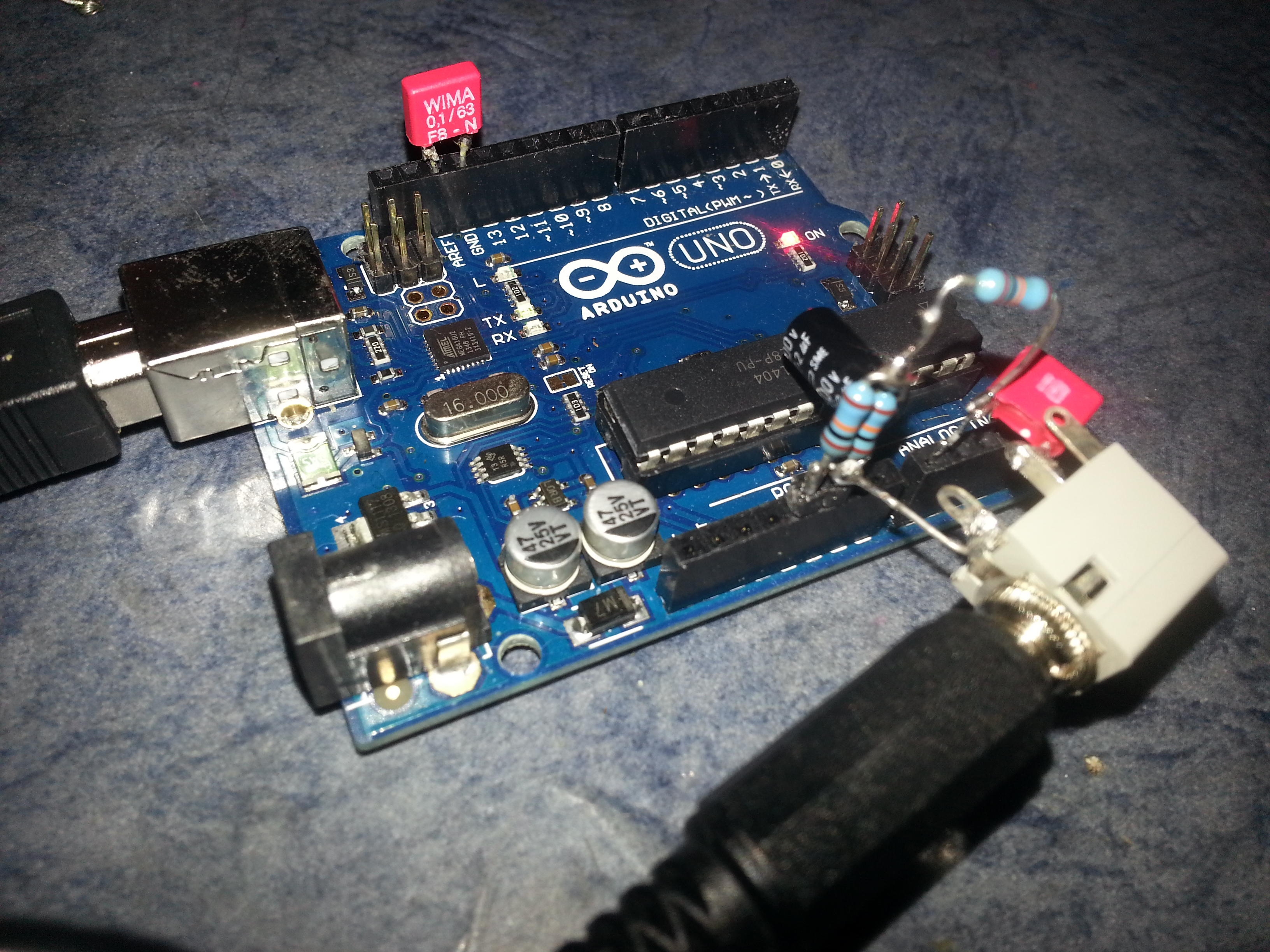
I built a very crude interface for the radio, which consisted of two 10 kilo-Ohm resistors and a 1uF capacitor to block the ADC bias voltage from breaking the radio. Simple! Only that it didn’t work. I could see the DCD light blinking (digital pin 13) and so I decided to see what was going wrong. The first thing I did was to connect a scope up to the input of the ADC (analogue pin 0) and see the bias. With VCC at 4.777 VDC and with no audio feed from the radio, the ADC pin was biased at 2.386 VDC (~ 20mV pk-pk noise). I wasn’t happy with that, so I followed the trend and added some capacitors to help clean up the bias voltage.
The second attempt at the radio interface was to use two 10K resistors with a 2.2uF capaictor to ground, to add a bit of smoothing to the bias voltage. This voltage was then coupled to the ADC pin with another 10K resistor. I added a 100nF across the VREF voltage and fed the audio in via a 100nF capacitor replacing the 1uF used before (because that’s what everyone else did). This didn’t make any difference at all to the functionality of the code – I still hadn’t seen a single packet, but the bias voltage had a noise level of around 5mV now, so it was considerably cleaner.
Here we see the tacked together implementation of the input basing. Since the ADC can detect signals in the range of 0 to 5V (under standard configuration) it is required what we lift the centre 0V signal to become centre 2.5V (half way in the range). Here I am using the Arduino Uno – I have also tried an Arduino Mega 2560.
Below, you see the bias voltage on the ADC input AN0 with no input signal.

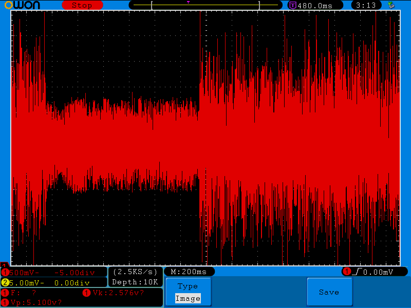
Here, the input has been added and the receiver is just outputting white noise.
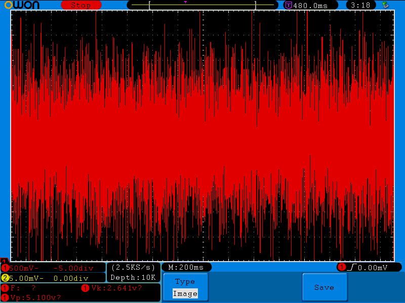
Here a packet is present in the interval, and appears as quieter noise.
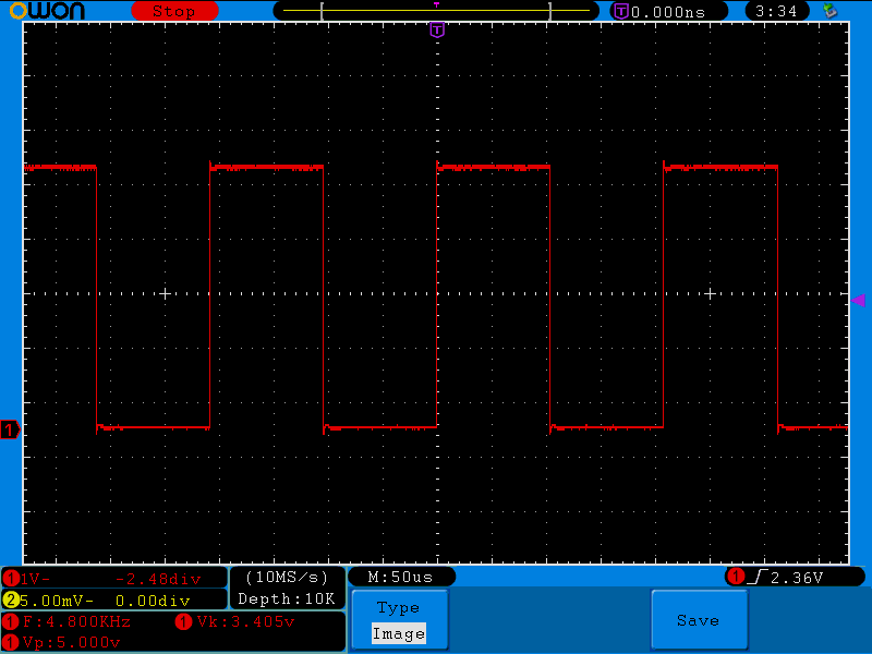
This is the heartbeat signal. Every time the ISR expires for the ADC timer, the pin is toggled and a sample taken. The frequency is half the sample rate, so here 4.8 kHz shows a 9.6 kHz sample rate as with version 0.10 of KI4MCW’s code.
If we look at the output of the TX0 line (first UART) we see some RS232 data at inverted TTL levels, heading for the USB chipset.

Using version 0.14 of KI4MCW’s code, arduino_tnc_014_w_tx, I was able to get good performance. The function is as good as any TNC I have used in the past, and I believe superior to some sound-card based approaches such as this: AX25 Soundmodem. We will see.
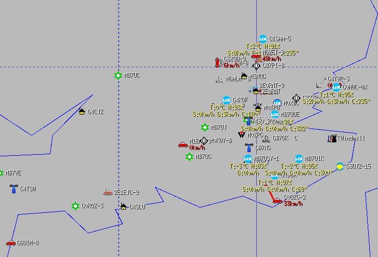
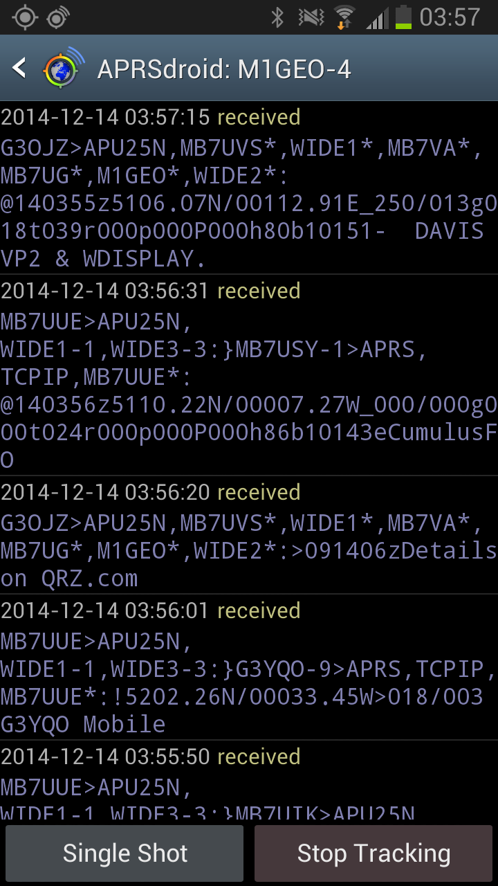
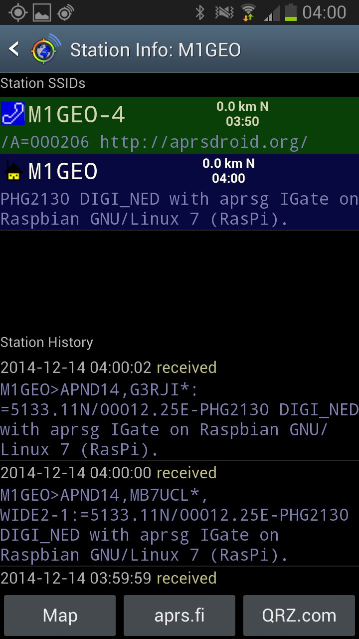
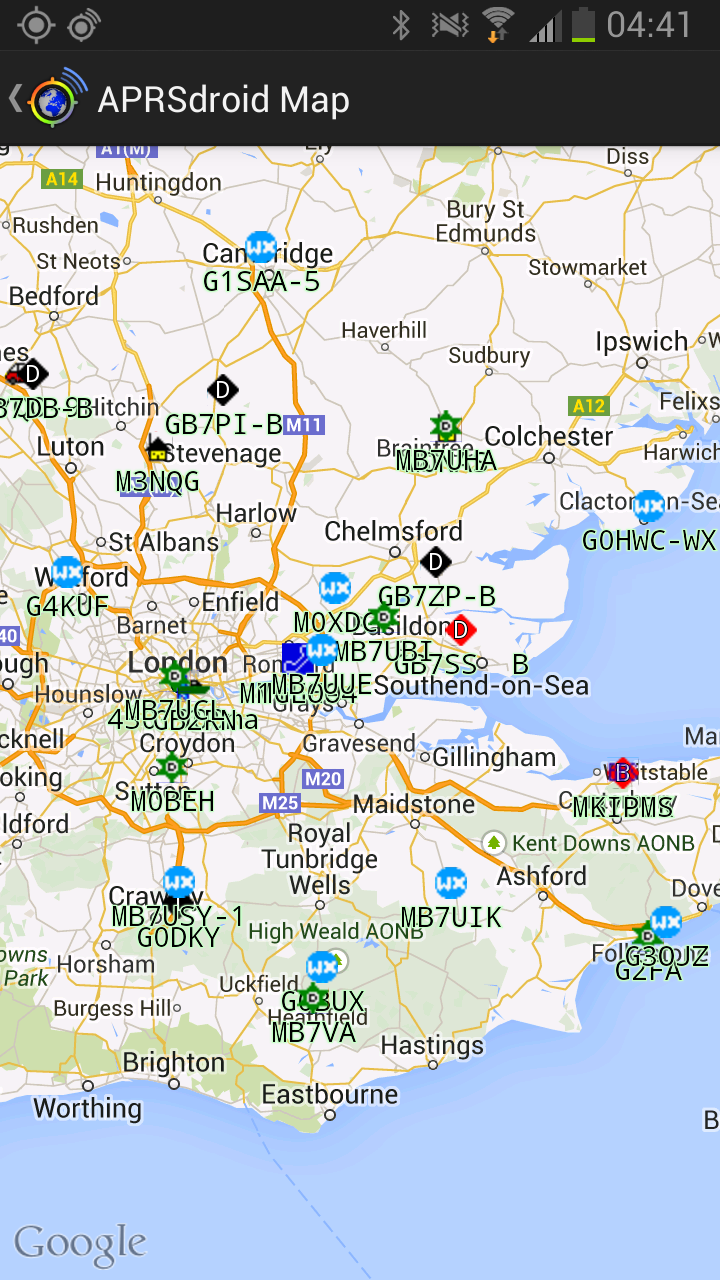
The final goal for this project was to act as a way to view data on my mobile phone, using the car’s APRS hardware. In the car I already have an APRS Tracker which I am keen to retain – it does an excellent job of sending out APRS beacons. However, I wanted a way to view the received data on my mobile phone. Using a Bluetooth RS232 Module provided the perfect answer. The Arduino TNC described above would generate RS232 data and the module would squirt it to my mobile phone via Bluetooth, if I wanted to. This then allows me to view maps and receive messages. I would like to also be able to transmit via this, but this is the next step.
I took my rusty old RS232 module and connected it to the Arduino shield as I had done before:
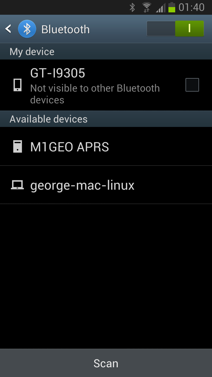
I then added the bias circuit to provide a simple way to get the analogue data into the Arduino Uno board. With a little effort, and a few commands added to the source code of the Arduino, I was able to get the Bluetooth module working once again!
 |
 |
 |
 |
PCB Prototype
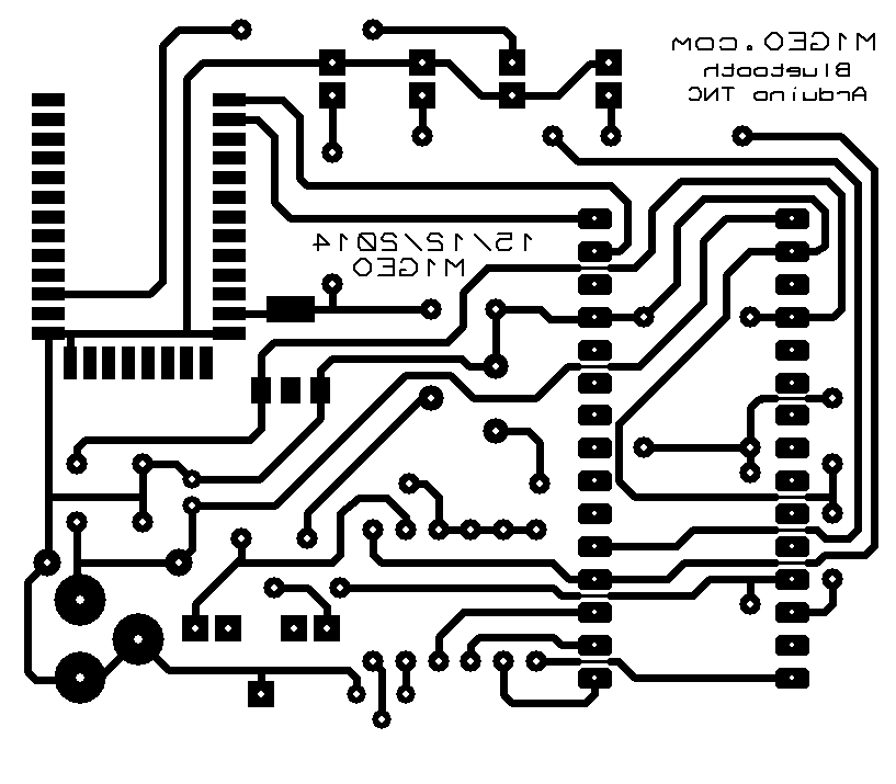
From here, I decided to try and make a board. The images below are for the first prototype, which worked perfectly. *It’s rough around the edges, but since I have been asked for it a few times, I may as well throw it up here: Please note the following:
This board is the first prototype. There are some bits to change…
- I think there is a conflict between the USB port and the Bluetooth module, when communicating with the Arduino MCU. If the Bluetooth module transmits some RS232 at the MCU for transmission, then it is sent successfully; however, if the FTDI FT232RL (on the arduino board) transmits RS232 at the MCU, the system seems to hang up for ages, with the Arduino repeatedly sending packet synchronisation frames over and over (for around 10 seconds) before sending the data. I suspect it’s some contention on the UART of the MCU, but it needs more work. Maybe a resistor to stop the devices crow-barring the supply rail? Without the Bluetooth module it works perfectly. Removing the resistors between the ATMEGA 328p and the FT232 chip also works because both solutions remove contention.
- The board needs some mounting holes.
- The LEDs are in an odd order at the minute.
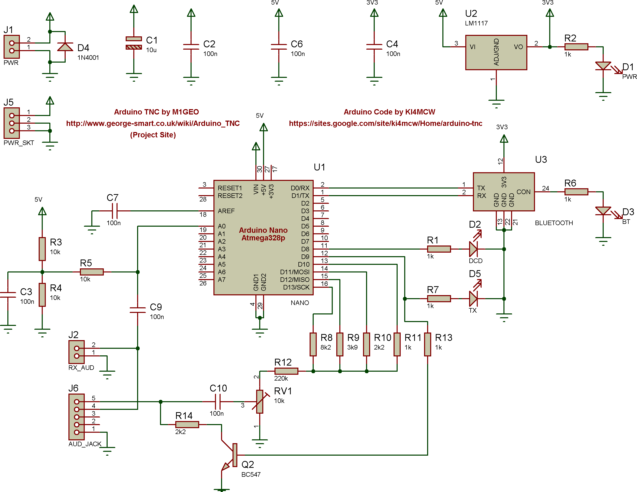
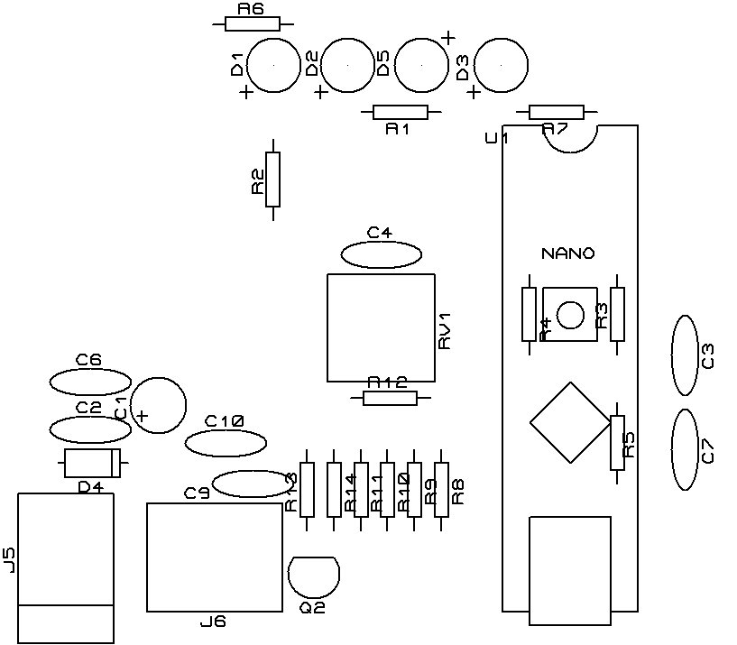
The following PDF files should be printed at 100% on A4 paper. Gerber files are also included.
- ArduinoAPRS_Proto1_Schematic.pdf
- ArduinoAPRS_Proto1_BottomCopper.pdf
- ArduinoAPRS_Proto1_TopSilk.pdf
- ArduinoAPRS_Proto1_Gerber.zip
As images, these are printed at 300DPI. Be sure to click through to the full sized picture, by clicking on the image for more information, and then clicking on the image again to get the original.
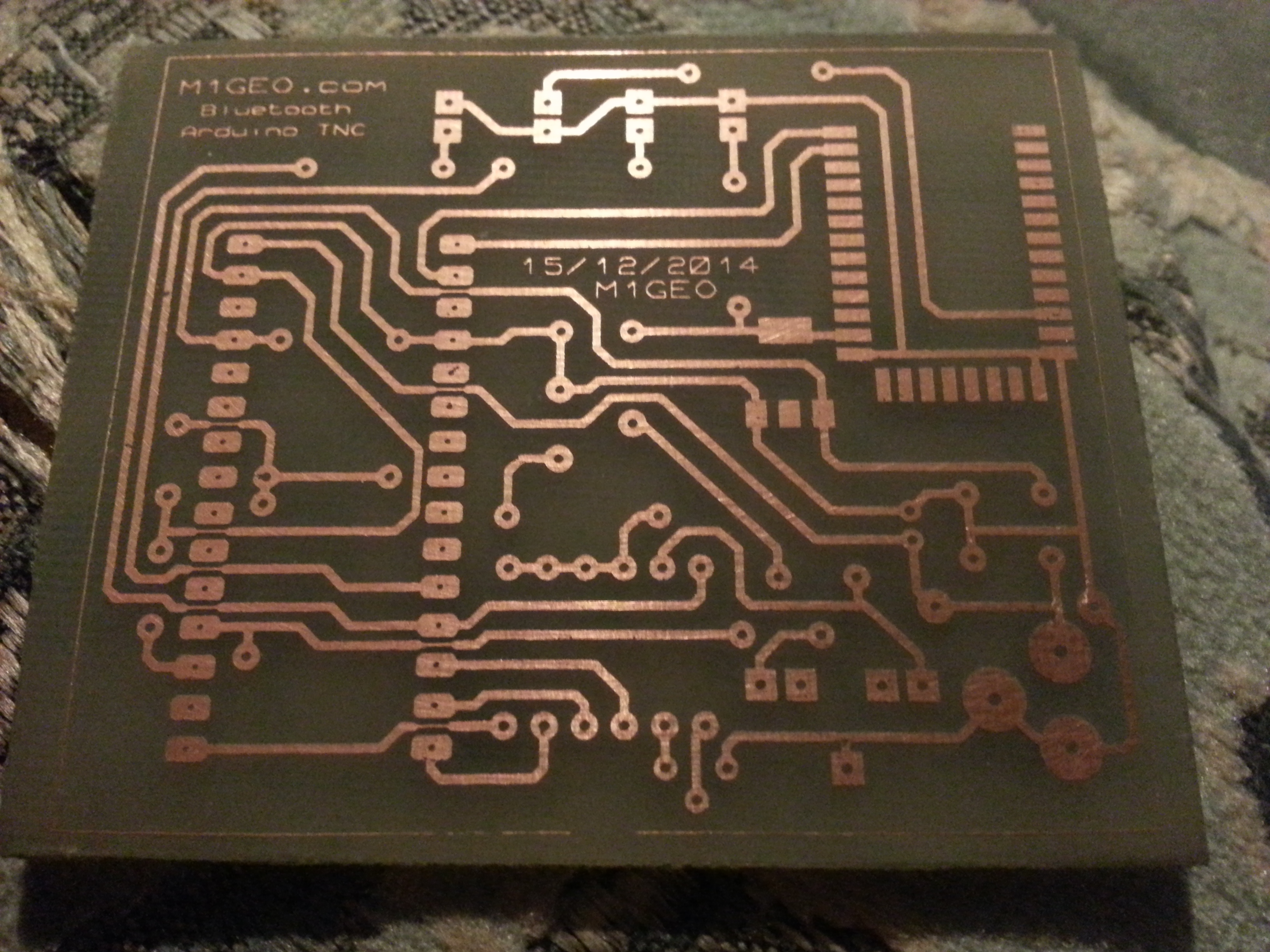
Here’s the board before etching at home:
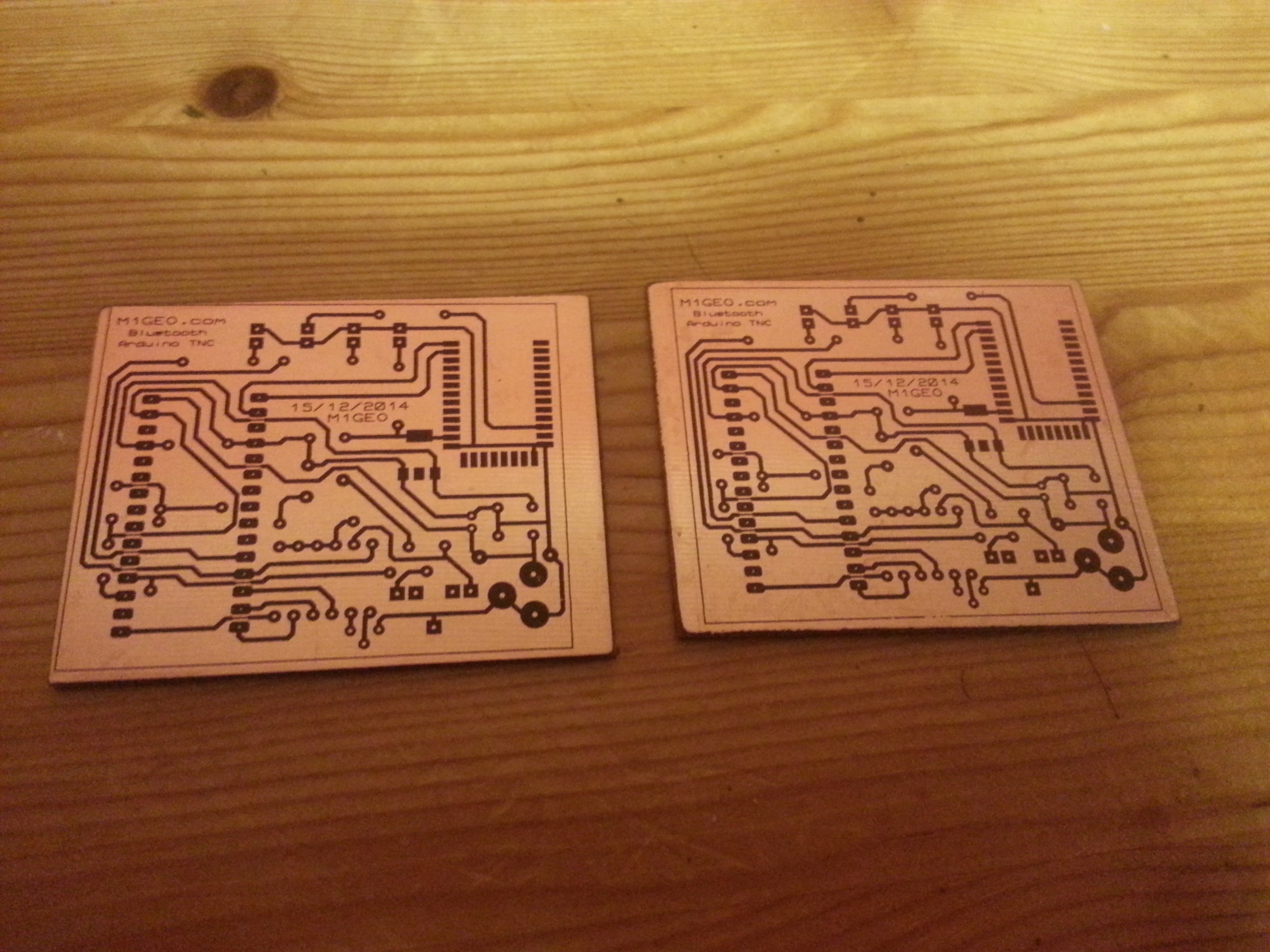
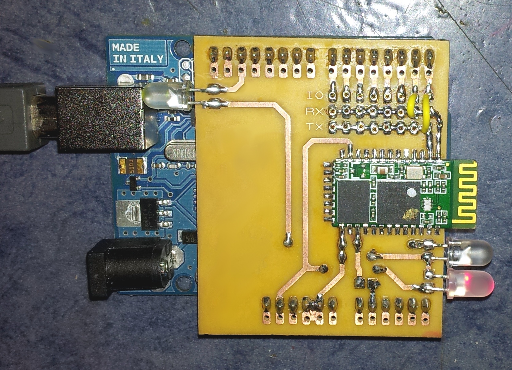
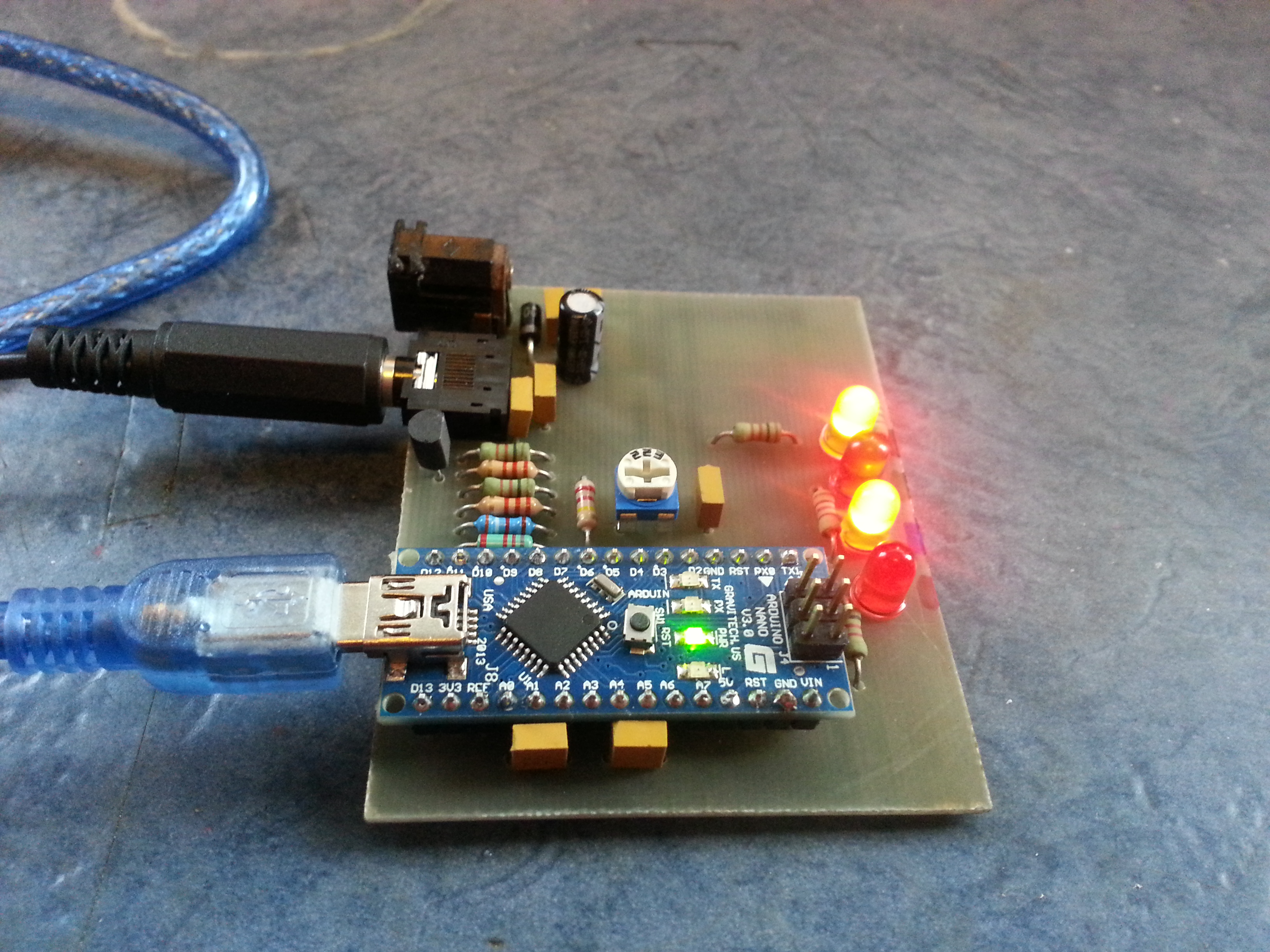
Using the Toner Transfer PCBs method, the boards were etched, resulting in something like below. I then populated the parts, adding the Bluetooth RS232 Module to the underside. I used a SMD regulator for the Bluetooth 3.3V as it was the cheapest way, they’re also large though that Stevie Wonder could solder it down, so no troubles from the anti-SMD lobbies there. £0.20 each beats £0.93 each for the through hole part.
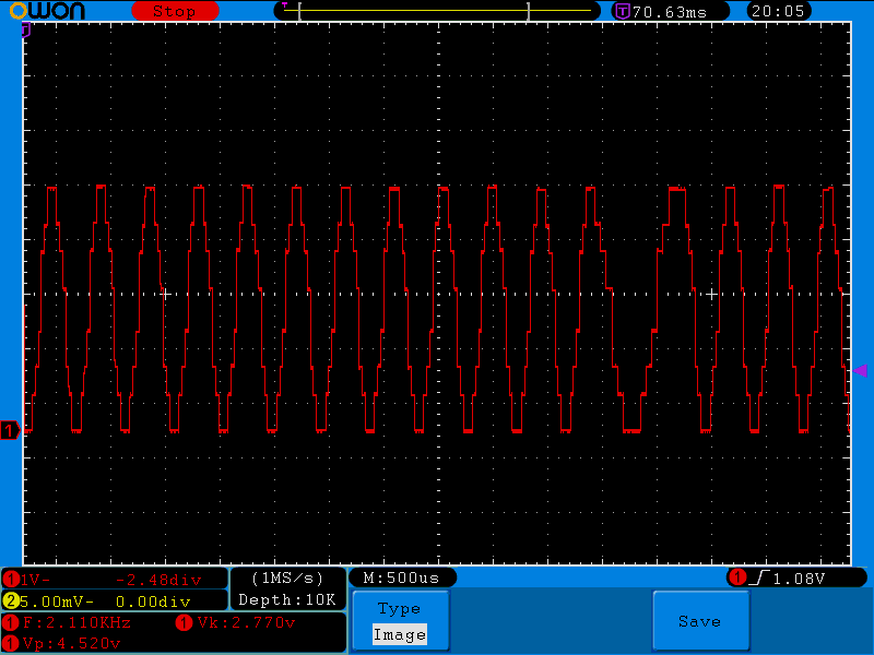
Once it was all working, I was finally able to test the transmitter part. Looking directly at the DAC (resistive) output, there was a very large waveform output, so it looked like it was working. It had the characteristics expected of a AFSK signal, so I looked further back at the “smoothed” waveform, adjusted the deviation pot, and transmitted it. To my amazement, it was received by my own APRS hardware – Success!
At the moment of writing, I am going to use the device for a while, see if it fails or falls over, and see if it is up to the job. I don’t intend to use the transmitter function, but as I was going to the effort of making boards, and given I do a lot with APRS and TNCs, I decided it would be worth the agrovation and add those bits on.
Since many people keep missing the source code links in the text, here again is a link to the source code by KI4MCW. In this article, I used arduino_tnc_014_w_tx.pde.
This is an ongoing project. 15 December 2014, 16:43 GMT.