This page came about one night when talking on 2 metres FM to G7UVW. During our QSO, the microphone cut out and I couldn’t seem to get any audio out of the microphone. It just stopped, half way through a QSO. Expecting the lead, I swapped with another (I have 2 FT817’s and an FT857) rig and found the lead to be okay, but the microphone unit was faulty. Further investigation showed the dynamic microphone coil resistance to be around 2.8 mega-Ohms. I suspect (with no evidence) that these are nominally 600 Ohm coils, and so this was at fault.
Although I had a spare dynamic element, from an old Tait T500 microphone, I opted to use an electret condenser element instead because I had heard good things – they offer more punchy and fuller sounding audio. I tacked it together on the back of the microphone and the results were good. The rest of this page documents how I went about in modifying it to a reasonable standard.
The first thing I did was found a piece of cardboard and cut a circle the same size as the faulty dynamic element. Then I made a smaller hole inside to hold the electret element.
 |
 |
Next I placed the electret element into the cardboard ring, and then hot glued it in carefully. The idea being that there would be some air space between the microphone and the element, to absorb some of the physical creaking that sometimes occurs as well as to baffle some of the puffy sounds our voices make. That’s the idea; and it worked to the best I can tell.
 |
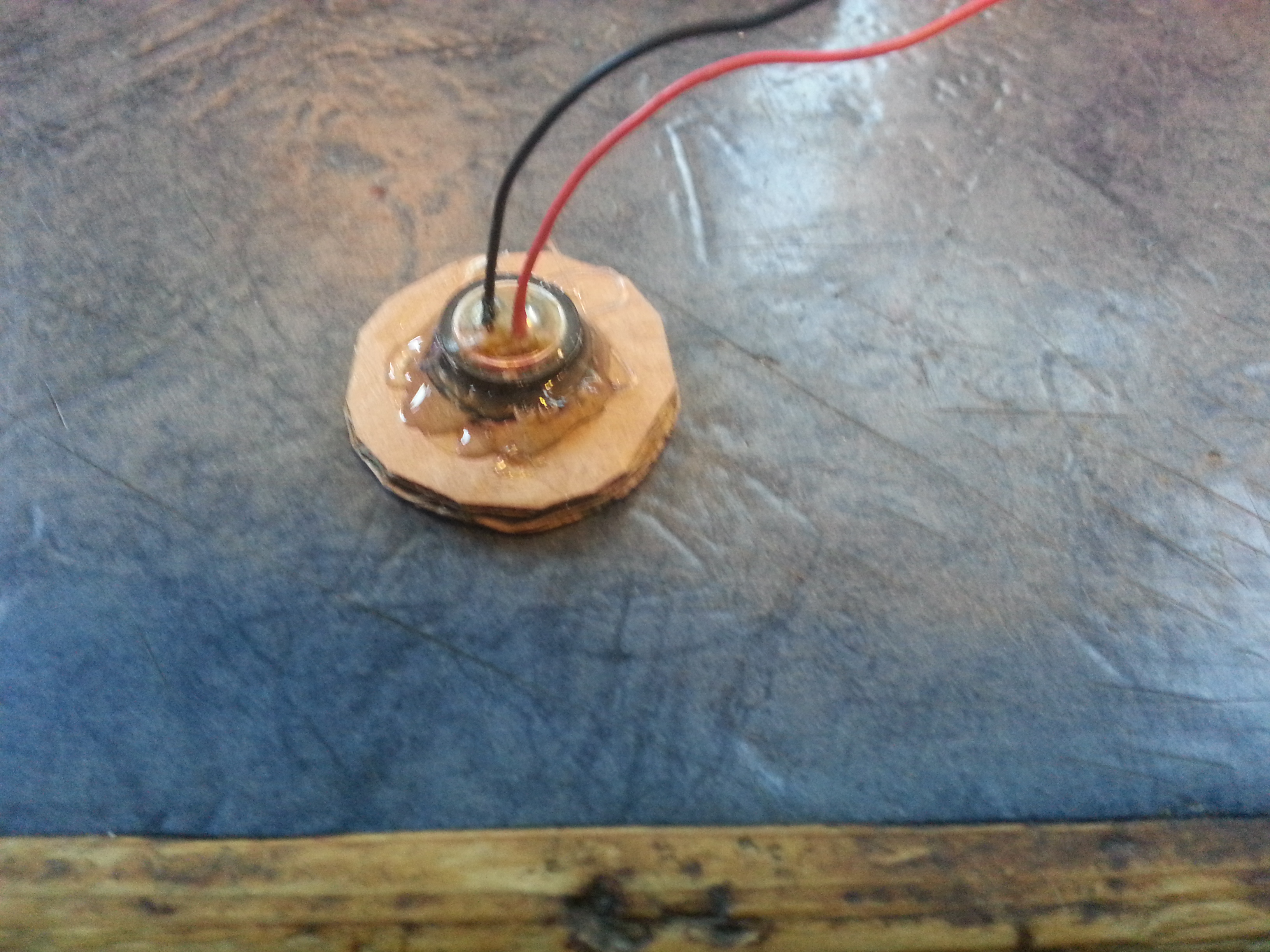 |
I then glued the whole thing into the microphone space where the dynamic microphone had come from.
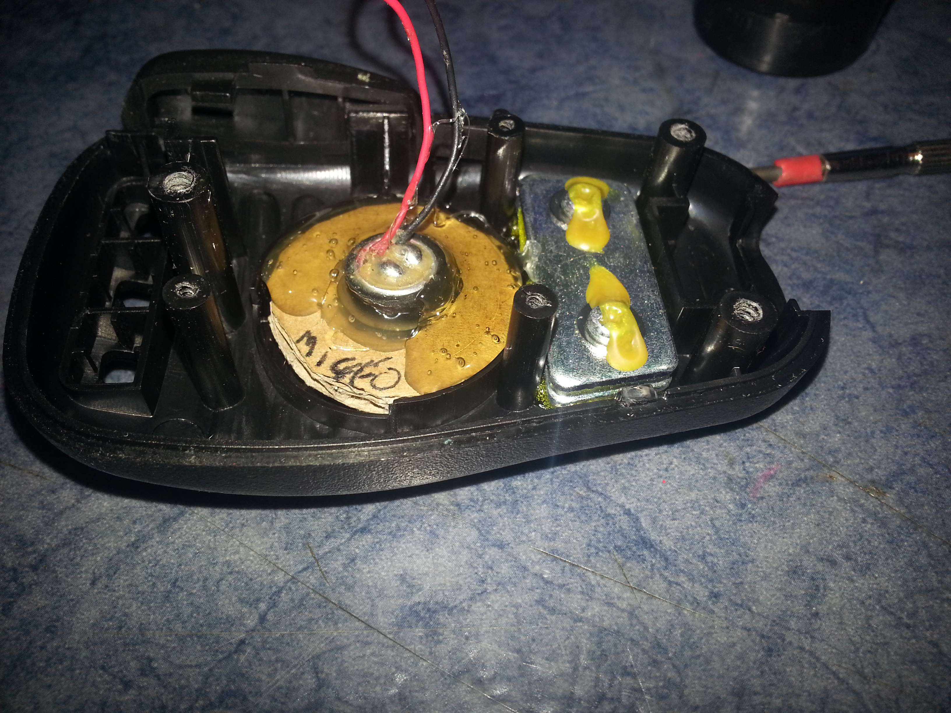
Once the glue has well set, it’s time to wire the electrical parts up. I used the exact same values as John, M0UKD who has done similar. Here, I show his schematic taken from the link above:
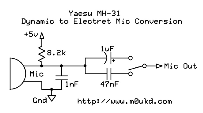
I started by adding the 1 nano-Farad capacitor across the microphone connection. Then I added the 8.2 kilo-Ohm resistor from the 5V power line to the signal side of the microphone, as shown in the picture below. Notice that I have put some plastic sleeving over the resistor wires.
 |
 |
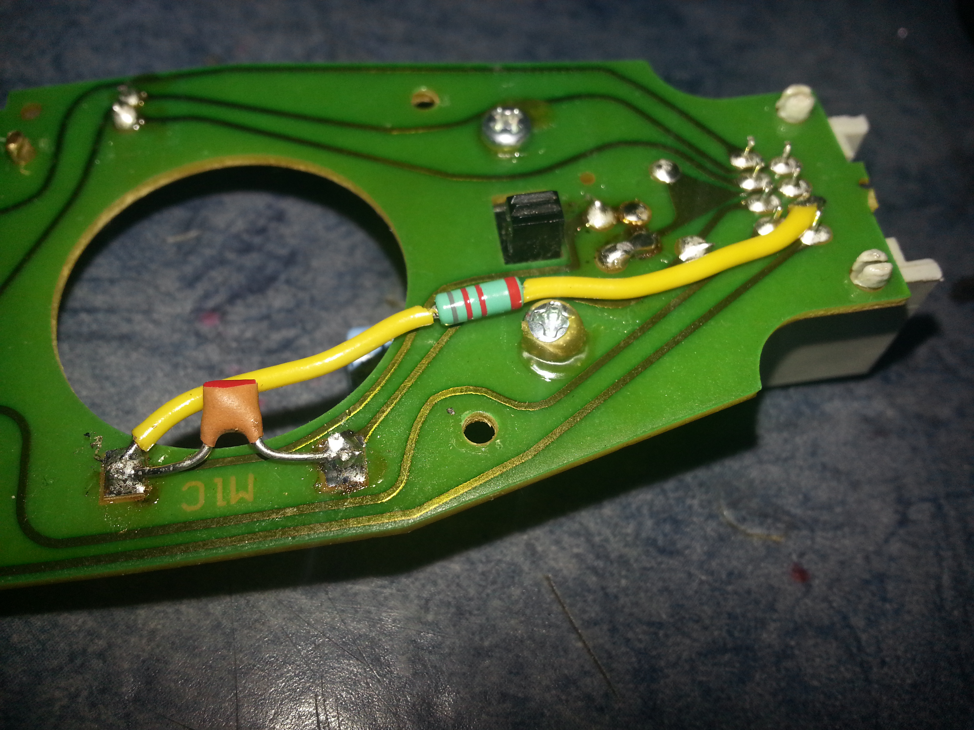
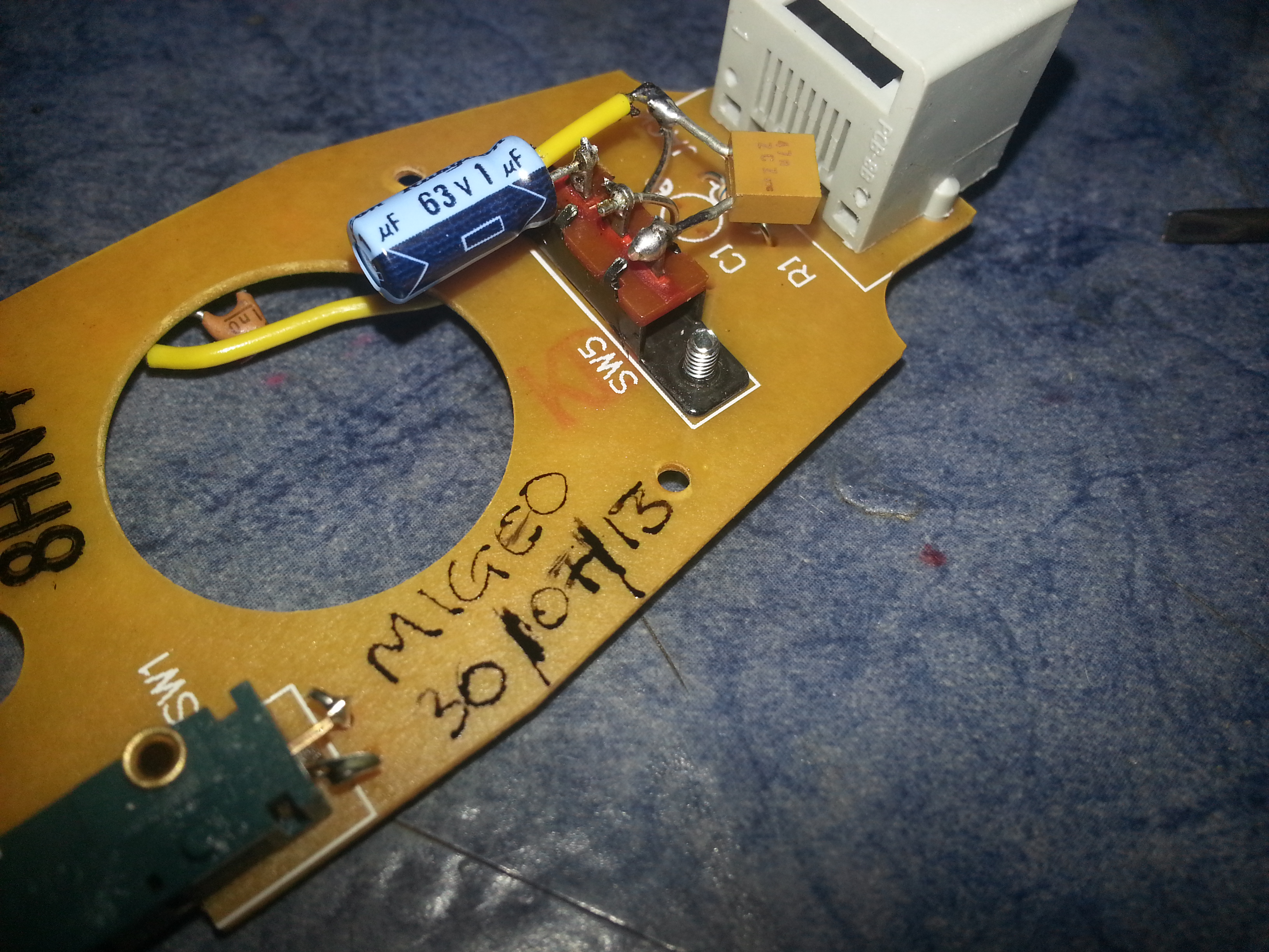
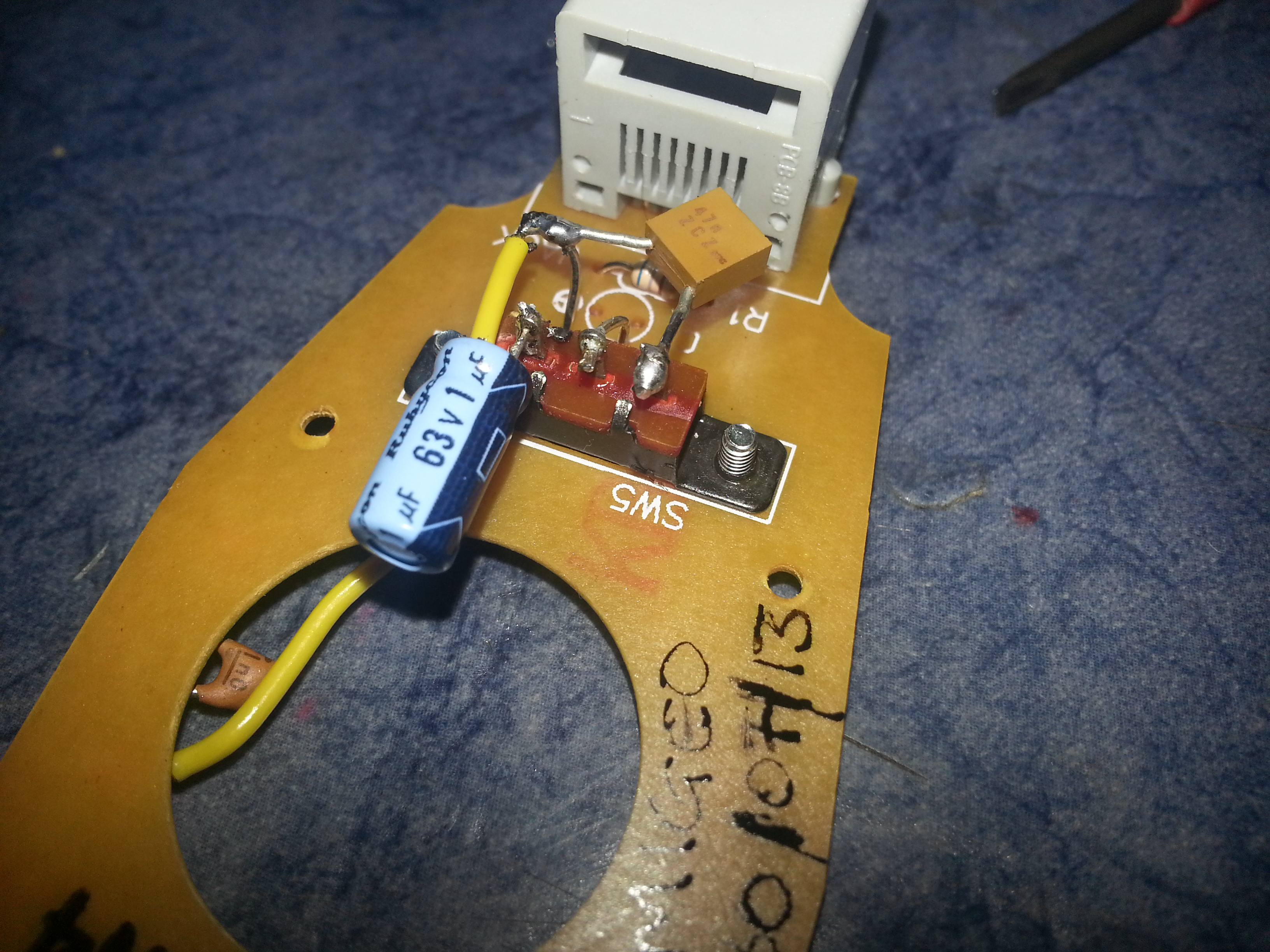
Next we change the two capacitors inside the microphone. I followed John’s lead and went with 1 micro-Farad and 47 nano-Farad with the switch between – this gives good bass response on the 1 uF capacitor for standard rag-chews – the 47 nF gives very thin and punchy audio for DX chasing on SSB.
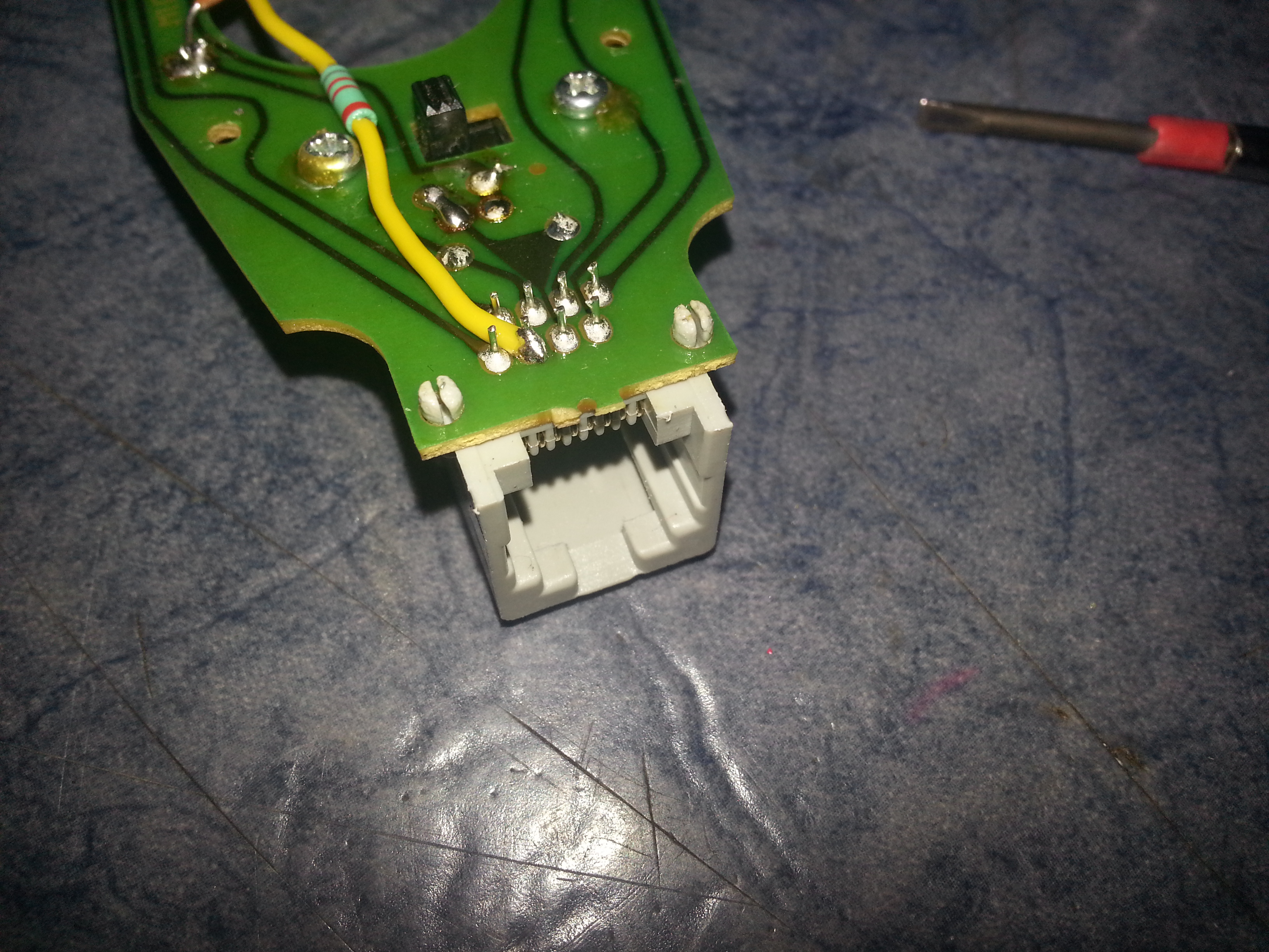
I removed the 0.33 uF capacitor from the microphone. That done, place the microphone down on the table such that the back of the switch is facing up with the radio connector towards you. In this orientation, disconnect the right wire from the switch back, leaving only the middle wire connected. Maintaining this orientation throughout, connect the negative side of the 1 uF capacitor to the right side of the switch, and the positive side to the wire you just removed from the switch. The 47 nF capacitor goes from the left switch output to the same removed wire. See the two images below.
 |
 |
Finally, connect the electret element to the reverse side of the board, across the 1 nF capacitor, observing the polarity; the mic connection furthest from the radio socket is the positive side, and carries the signal – the other tab is microphone ground.