
With a change in driving habits, I was having issues with the car battery draining over the week that I didn’t use the car for. Upon investigation, it turned out to be an issue with the APRS tracker (FoxTrak) and GPS being powered on always. These caused a considerable drain on the battery. I measured the currents of the associated devices. Here’s what I measured:
 |
4 mA |
 |
175 mA |
 |
6160 mA |
 |
21 mA |
 |
155 mA |
It was clear that I needed a way to turn the GPS off when it wasn’t required, and for that matter, the FoxTrak too. As the radio, GPS and Tracker are mounted in the boot of the car, and the front panel located in the drivers cabin, the thought of running more cables around the car wasn’t too appealing. Then I had an idea. Using the Yaesu FT-7900E (radio)’s power status to guide the power status of the GPS and Tracker would be ideal – this doesn’t require any additional cabling and, if done properly, would allow for the radio’s Auto-Power-Off to turn the GPS and Tracker off should I forget to do so myself! Excellent!
The next thing was to work out how to tell if the radio was turned on or not. There were two ideas suggested to me in the FT-7900’s Yahoo Group.
# Using the DATA connector’s PTT control voltage (this pin is powered, and shorted to ground to cause the radio to transmit).
# Using the DATA connector’s 9K6 output, as this is unsquelched (detecting ‘noise’ on this pin would indicate the radio is on).
There is of course one blatant issue; when the radio transmits the PTT voltage would be low, as to signal the radio had powered off, and; the 9K6 line would also be silent while transmitting, as to indicate once again the radio was off. A simple monostable circuit, perhaps using a NE 555 timer would allow for these ‘silent’ periods to be smoothed out for a short time, say 1 minute. This way, the GPS & Tracker would stay on for 1 minute after the radio powered off; after a minute the GPS & Tracker would power down also.
The next step was to characterise the DATA PTT line under various circumstances. Below is a tabulation of the line voltage:
 |
0.006 V |
 |
4.90 V |
 |
4.89 V |
 |
0.016 V |
As you can see, keying the radio from the microphone does not effect the PTT line voltage enough to matter, and the signal is indeed changed when the radio is powered off.
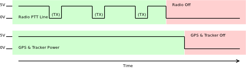
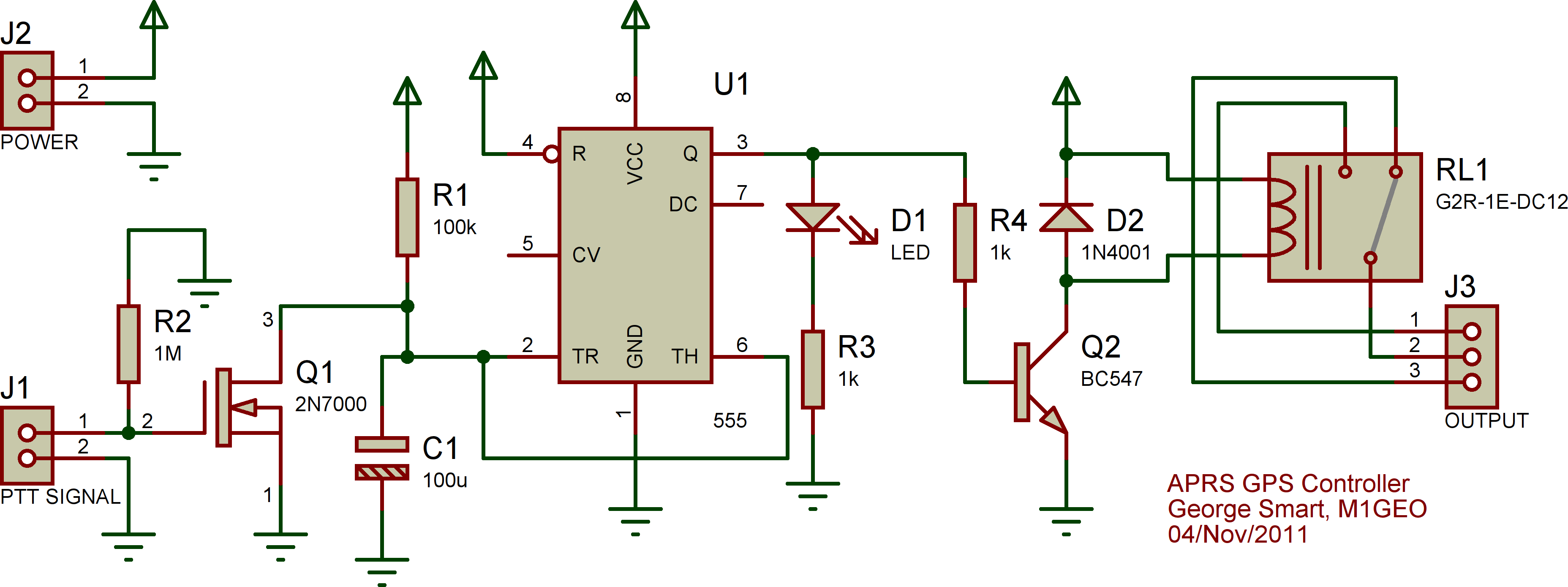
The solution is what is called a retriggerable monostable. A monostable timer is a timer that has a fixed time element to it; it is unstable in only one state and after a specific time (hear this time is a parameter we can choose) it returns to it’s one stable state. With the NE 555 IC, this stable state is once the capacitor is charged to over 2/3rds of the supply voltage. By using a 2N7000 MOSFET, we can short this capacitor preventing it from charging at all, therefore holding the 555 in it’s unstable state. When the PTT line drops, the MOSFET stops shorting the capacitor, and the 555 starts timing as usual. If the radio was transmitting an APRS frame, then after a few seconds, the PTT voltage will reappear, the MOSFET reconduct and short out the capacitor once more – the net effect is that the capacitor never got to 2/3rds of the supply voltage and so the GPS was never turned off. If on the other hand the PTT voltage disappears due to the radio being powered off, then the PTT line may not appear within the 10 second window designed, and the GPS will be powered off. The schematic below is of the circuit I designed and used for my APRS GPS Controller.
I then took a few measurements to just check things are as expected.
 |
10 mA |
 |
189 mA |
Although now the idle powered off current as risen to 10 mA, is is still much lower than the 160 mA required to run the GPS. The circuit works exactly as I had hoped.